High Energy Density Polyaniline/Exfoliated Graphite Based Supercapacitor with Improved Stability inWide Voltage Window
Sayed Mohammed Adnan1, Sadaf Zaidi1* and Inamuddin2
1Department of Chemical Engineering, Faculty of Engineering and Technology, Aligarh Muslim University, Aligarh, 202002, India.
2Department of Applied Chemistry, Faculty of Engineering and Technology, Aligarh Muslim University, Aligarh, 202002, India.
Corresponding Author E-mail: sadaf63in@yahoo.com
DOI : http://dx.doi.org/10.13005/ojc/370227
Article Received on : 13-Mar-2021
Article Accepted on :
Article Published : 20 Apr 2021
In this work, polyaniline/exfoliated graphite-based conducting polymer composites have been prepared and brought under speculation to improve the stability at a high voltage window, ultimately improving the material's supercapacitance behavior. The specific capacitance of 356 F/g at a scan rate of 10 mV/s in the potential window -1V to +1V and cycling retention 82 % after 1000 cycles using aqueous electrolyte (0.1 M Na2SO4) at ambient condition is reported. The energy density and power density are found to be 318 Wh/kg and 12.5 kW/kg, respectively, at a specific current density of 12.5 A/g. The developedcomposite is stable, even at high voltage. This composite obtained is low cost and is stable in aqueous solutions in a wide voltage window.
KEYWORDS:Conducting Polymer; Exfoliated Graphite; High Energy Density; Supercapacitor
Download this article as:| Copy the following to cite this article: Adnan S. M, Zaidi S, Inamuddin I. High Energy Density Polyaniline/Exfoliated Graphite Based Supercapacitor with Improved Stability inWide Voltage Window. Orient J Chem 2021;37(2). |
| Copy the following to cite this URL: Adnan S. M, Zaidi S, Inamuddin I. High Energy Density Polyaniline/Exfoliated Graphite Based Supercapacitor with Improved Stability inWide Voltage Window. Orient J Chem 2021;37(2). Available from: https://bit.ly/3gEK4lZ |
Introduction
Super capacitors are electrical energy harvesting devices that accumulate energy through static charging, typically by electrical double layer capacitance (EDLC) combined with fast Faradaic charge transfer ensuring high power density, fast charging, and excellent cyclability 1. Metal oxides of manganese, ruthenium, nickel, etc. and conducting polymers like polyaniline (PANI), polythiophene, polypyrrole, polyindole, polyacetylene, including their composites, act as pseudo capacitive materials that have much higher specific capacitance and energy density than metal or carbon materials alone2 . Unlike metals and carbon, the high energy density of conducting polymers is compromised by their short cycle life due to the polymer skeleton’s degradation during the redox process 3. In contrast, conducting polymers and transition metal oxides have noticeable benefits since they might deliver higher pseudo capacitance through redox responses using the electrolyte ions over the surface of electrode. Among the most appealing pseudo capacitive materials, PANI (theoretical capacitance of 1200 F g−1), is attractive for its high conductivity, conveniencein synthesis, and inexpensive preparation 4.
In the previous researches, the energy density of 79 Wh kg-1, 65.3 Wh kg-1, 250 Wh kg-1 and 150 Wh kg-1 was obtained for Graphene/PANI/CNT 5, PANI/3D carbon6, Dimercaptan-PANI7, PANI/porous carbon8 respectively.The present research is focused on maximizing the energy density by improving specific capacitance and voltage window. PANI electrodes show high capacitance and lag in performance only by polymer chain degradation at high value of voltage window. It is speculated to form PANI-based composite that inherits PANI’s high capacitance, and long stability/cycle life contributed by the composite material9-13. Here we prepared PANI-EG (polyaniline-exfoliated graphite) based composites that can show improved properties compared to pure PANI in terms of stability and can survive even at a high potential window.
Materials and methods
Materials and characterization
All the chemicals were purchased and procured from Sigma Aldrich and Merck in their purified form.
The powdered sample’s x-ray diffraction (XRD) patterns were captured using a MiniFlexTM II benchtop XRD system (Rigaku Corporation, Tokyo, Japan) set to 40 kV.The powdered sample was mixed with spectroscopic grade potassium bromide (KBr) in a ratio of 1:100 for FTIR spectroscopic measurements, and spectra were recorded in the range of wavenumber 400–4000 cm1 on Perkin Elmer FTIR Spectrum BX (PerkinElmer Life and Analytical Sciences, CT, USA) in the diffuse reflectance mode at a resolution of 4 cm-1 in KBr pellets. The thermal stability of the sample was investigated using thermo gravimetric analysis (TGA) (Sieco SII, SSC5100, Instrument) under nitrogen atmosphere at a heating rate of 10 K min-1.
Preparation of Exfoliated Graphite (EG)
EG was synthesized by following the modified Dhakate, et al. method[14]. Natural graphite was dehydrated at 353 K for 10 h in a vacuum prior to oxidation treatment. This natural graphite (50mg) was subsequently blended with H2SO4 (98%, 75 mL) and HNO3 (65%, 25 mL) at room temperature for 24 h. After 24 h, graphite intercalated compound (GIC) was obtained, where HNO3was an oxidizer and H2SO4the intercalant. Further this mixture was agitated to obtain an orderly intercalation of every graphite flake. The obtained intercalated graphite compound of PANI was rinsed and filtered with distilled water until it reached a pH of 7, then dried at 373 K for 4 hours to remove residual water through dehydration. The dry GIC that resulted was heated to 1273 K for 30 seconds to obtain the exfoliated graphite (EG). The whole procedure is depicted in pictorial form as shown in Figure 1.
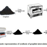 |
Figure 1: Schematic representation of synthesis of graphite intercalated compound (GIC). |
Preparation of Polyaniline-Exfoliated Graphite (PANI-EG) Binary nanocomposite
PANI-EG nanocomposites were prepared by emulsion polymerization pathway using aniline and exfoliated graphite (EG) as reactant. The typical experiment was performed as follows: Firstly, exfoliated graphite(500 g) and emulsifier, sodium lauryl sulphate (SLS) (1mM) was added into 20 mL of ethanol under ultrasonication for 1 h and then it was added to the 60 mL of 1.0 M HCl containing 1.0 mL of monomer of aniline. Subsequently, benzoyl peroxide (2 mL) in 30 mL of xylene was used as oxidizer for the polymerization. The prepared oxidizer was incorporated into the monomer containing the aqueous phase and the reaction was carried out with magnetic stirringat 298 K (room temperature) for 24 h. After that the mixture was added into 250 mL acetone. The green polyaniline with EG precipitate was subsequently rinsed with 100 mL of acetone,furthermore the mixture was washed by adequate quantity of water. The nanocomposite was finally dried at 343 K for a duration of 24 h. The yield, conductivity and density of the PANI EG nanocomposite on varying the weight from 0% to 100% is tabulated in Table 1.
Table 1: Variation of conductivity of polyaniline (PANI) with variation in exfoliated graphite (EG) content.
|
Entry |
Ex.Graphite( wt %) |
Yield (g) |
Conductivity (S/cm) |
Density (g/cm3) |
|
PANIEG0 |
0 |
0.84 |
4.766 |
1.32 |
|
PANIEG10 |
10 |
0.99 |
21 |
1.27 |
|
PANIEG20 |
20 |
1.05 |
50 |
1.35 |
|
PANIEG30 |
30 |
1.1 |
72 |
1.26 |
|
PANIEG40 |
40 |
1.3 |
75 |
1.36 |
|
PANIEG50 |
50 |
1.4 |
81 |
1.69 |
|
PANIEG60 |
60 |
1.42 |
99 |
1.48 |
|
PANIEG70 |
70 |
1.52 |
102 |
1.38 |
|
PANIEG80 |
80 |
1.6 |
110 |
1.49 |
|
PANIEG90 |
90 |
1.71 |
125 |
1.51 |
|
PANIEG100 |
100 |
1.85 |
198 |
1.49 |
Electrochemical Studies and Electrode Preparation
Electrochemical experiments were carried out on glassy carbon electrodes (GCE) with a diameter of 3 mm. Briefly, three GCE is thoroughly rubbed with alumina slurries, cleaned several times with DI spray, and dried. Regarding that, 10 mg of sample powder was dissolved in ethyl alcohol (5 mL) by sonication for one hour to stabilize suspension. The CV profile was calculated at various mass loadings (i.e., 1, 3, 5, 7, 9, µL, respectively) for super capacitors, and after taking into account all of the variables, including current performance, charge diffusion, CV form, and area under the curve, etc., the 5 µL loading was observed to be the highest. Following that, 5 µL suspension was drop-cast onto the active region of GCEs and cured beneath infrared lamp irradiation upon being coated with a smooth surface of Nafion. The modified GCEs were washed three times with DI water and dried before being incorporated into the electrochemical setup.
The electrochemical studies were completed on Auto lab PGSTAT 302NN electrochemical workstation (NOVA software interface; version 1.11) controlled through a PC. A standard three-electrode arrangement associating platinum wire used as a counter electrode, Ag/AgCl for reference electrode, and glassy carbon electrode (3 mm diameter) utilized as the working electrode was integrated. Sodium sulphate (0.1 M Na2SO4) was chosen as the electrolyte for all electrochemical studies. All specifications were carried out at standard condition of room temperature (298 K).
The following equations were used to calculate the specificcapacitance of the electrode materialusing the dataobtained from the CV voltammograms and galvanostatic charge-discharge curves respectively 15.

Also, the energy density and power density were calculated by the following equations.

Where I (A) is current obtained from CV curve, E(volt), V (volt) orΔV (volt)is restricted voltage window, ν is the time-rate of change of voltage or scan rate, Δtis the time duration of one complete cycle and m is the deposited mass of sample on the surface of electrode. Ed and Pd are the energy density and power density respectively.
Results and Discussions
3.1 X-Rays Diffraction (XRD) Studies
In Figure 2, the XRD pattern of pure EG reveals the hexagonal system of graphite with the peaks at 26.6, 44.6, and 54.80 through their corresponding miller indices plane (002), (101), and (004)16. Additionally, XRD pattern of the pristine polyaniline (Figure 2a) demonstrates the peaks at 9.5, 15, 22, and 27 with a shoulder at 29⁰; this corresponded to a semi crystalline nature of polyaniline in emeraldine form 17, 18. The XRD pattern of PANI-EG nanocomposites (Figure 2c) indicates the comparable pattern of PANI (Figure 2b) along with EG (Figure 2a). This result indicated the presence of exfoliated graphite intercalated with the polyaniline matrix.
 |
Figure 2: XRDpatterns of (a) exfoliated graphite (EG), (b) pure polyaniline (PANI), and (c) polyaniline-exfoliated graphite (PANI-EG) composite. Click here to View figure |
FT-IR Spectroscopic Study
Figure 3 exhibits the FTIR spectrum of EG pristine PANI and PANI-EG composite. In the FT-IR spectrum of EG, the peak at 1571 cm-1, 1631 cm-1, 2925 cm-1, and 3444 cm-1 correspondingly C=C symmetric stretching vibration, C=O stretching of carboxyl functional
 |
Figure 3: FT-IR of polyaniline-exfoliated graphite composite (PANI-EG). |
groups, stretching of the C–H bonds and O–H stretching vibration 19-23. Throughout the intercalation of natural graphite by highly concentrated acid mixture, a few of the carbon double bonds are oxidized, which triggers the development of carboxylic and hydroxyl functional groups on the exfoliated carbon surface. The FTIR spectrum of the synthesized PANI-EG (Figure 3c) composite gave absorption bands at 3446, 2925, 1632, 1468, 1273 and 1118 cm-1 quite similar to that of pristine polyaniline (Figure 3b) 24 and their corresponding functional groups as secondary amine (-NH) in the polymer backbone, stretching of the C–H bonds in phenyl rings, C=C benzenoid ring, C=C quinoid rings, and C–N–C bonds. The wide band starting from 1000 to 1400 cm-1 was assigned to C–N or C–H in plane distortion modes and owned a maximum at 1118 cm-1. Newer and more effective peaks are found at lowered wave number in between 400–800 cm-1 attributable to the C–H exterior bending vibration, C–H in plane bending and out-of-plane C–H wagging. The infrared spectrum of the PANI-EG composite (Figure 3c) observed that the peaks due to quinonoid, and benzenoid absorptions are 1646 and 1464 cm-1 for pure polyaniline shifted to 1632 and 1468 cm-1 in the PANI-EG composite and such change is attributable to the conjugation effect between the C=C of the benzenoid and quinoid ring and the graphite surface. The evidence indicated that the EG intercalated with PANI matrix 25.
Thermogravimetric Analysis (TGA)
The Thermogram curves of EG, PANI, and PANI-EG composites are shown in the Figure 4a, 3b and 3c from ambient temperature to 973 K under a nitrogen atmosphere at a heating rate of 10 K min-1. Thermal degradation preceding in the order of samples: EG > PANI-EG > PANI. The preliminary weight loss for PANI at a temperature of 383 K explains the loss of water molecules from the polymer matrix. In the EG, the weight loss at 523 K may be likely attributable to the unleashing of do pant groups. The last degradation temperature is revealed at 773 K. The significant wreckage happened at 523 K for PANI and at 623 K for PANI-EG nano composite, although due to the introduction of EG into the PANI matrix, the nano composite demonstrates improved thermal stability (up to 750 K) contrasted to PANI and PANI-EG nano composite 26.
 |
Figure 4: Thermogram of (a) EG, (b) PANI, and (c) PANI-EG binary composite. |
Electrochemical Studies
The cyclic voltammograms of PANI and PANIEG composites with varying compositions of exfoliated graphite are shown in Figure 5a. The specific capacitance (C), energy density (Ed) and power density (Pd) of the electrode material with varying scan rates have been summarized in Table 2.
Table 2: Specific capacitance, energy density and power density values of PANI EG30 composite at different scan rates and different current densities.
|
A. (Cyclic Voltammetry) |
B. Galvanostatic Cycling |
||||||
|
k (mV/s) |
C (F/g) |
Ed (Wh/kg) |
Pd (kW/kg) |
i |
C (F/g) |
Ed (Wh/kg) |
Pd (kW/kg) |
|
100 |
189.5 |
105.3 |
18.9 |
12.5 |
572 |
317.9 |
12.5 |
|
80 |
200.8 |
111.6 |
16.0 |
15 |
522 |
290.1 |
15.0 |
|
60 |
221.0 |
122.8 |
13.2 |
17.5 |
490 |
272.3 |
17.5 |
|
40 |
252.9 |
140.5 |
10.1 |
20 |
470 |
261.7 |
20.0 |
|
20 |
307.8 |
171.0 |
6.2 |
22.5 |
453 |
251.6 |
22.5 |
|
10 |
355.9 |
197.7 |
3.6 |
25 |
441 |
245.0 |
25 |
PANI and intercalated composites were analysed within the applied potential range of -1.0 V to +1.0 V. However, among the PANI and PANIEG composites, PANIEG30 (polyaniline 70%, exfoliated graphite 30%) showed maximum specific capacitance of 355.9 F/g at 10 mV/s scan rate with least variation with increasing number of cycles. On the other hand, PANI, PANIEG10 to PANIEG100, showed specific capacitance values below or comparable
 |
Figure 5: CV curves of (a) PANI-EG composites, (b) PANIEG30 at different scan rates, and (c) sp. capacitance vs sq. root of scan rateof PANIEG30 composite. |
to PANI EG30 but with increasing number of cycles their performance in terms of specific capacitance deteriorated. Though the peaks diminished when the percentage of EG was increased from 0% to 100wt%, the voltammogramsdid tend to become more rectangular. The combined effect of decreasing peak and rectangularity (which depicts high cycle life) brought the area to the maximum with improved cycle life, at EG composition of 30 wt% which resulted in the maximum capacitance of the PANIEG30 composite with high cycle life. The smaller peaks in Figure 5bat high scan rate and non-linearity in Figure 5c shows dominance of diffusion in charge mobility and pseudo capacitance behaviour of the material. The galvanostatic charge-discharge curve is depicted in Figure 6. The potential window for the galvanostatic cycling was fixed between -1.0 V to +1.0 V. The PANI EG30 composite was subjected to six different current densities of 12.5, 15.0, 17.5, 20.0, 22.5 and 25.0 A/g and 1000 cycles run was taken at current density of 25.0 A/g in order to observe retention capacity of the material. The specific capacitance, energy density and power density calculated against these current densities are presented in Table 2. The nature of the charge-storage response is evident from Figure 6a. The Faradaic curves and not straight lines clearly indicate the pseudo capacitance i.e. reactions occurring on the electrode surface apart from the surface double-layer charge storage mechanism1, 27. This fact is also confirmed by Figure 6b. where specific capacitance shows a parabolic decrease with increasing current density which must be linear in case of EDLC. The parabolic decrease validates that access to the pores of the material is the main constraint for the storage of the charge and the phenomena is more diffusion controlled and capacitance to the fullest can be exploited at lower current densities only 28.
The Ragone plot of PANIEG30 at distinctive current densities is revealed in Figure 6c. It is clear from the graph that the PANIEG30 possesses high energy density of 318 W h/kg and 245 W h/kg, and power density of 12.5 kW/kg and 25 kW/kg, at a current density of 12.5 A/g and 25 A/g, respectively.
Due to the effective π-π interaction between the PANI with EG, PANIEG30 showed excellent electrochemical behaviour. PANIEG30 showed high energy density which may be attributed to the reduced diffusion path for electrolyte ions during the course of redox reaction of 29.
At low current density, PANIEG30 showed high energy density due to the fact that Na2SO4 electrolyte ions permeate into the PANIEG30 electrode material that facilitated the interaction to the inner surface of the electrode material. The maintained high energy and power density at high current density of 25 A/g comes through the unchanged structural reliability of PANI EG30 nano composite even at high current density.
At high current density the approach of the electrolytic ions to the inside of the electrode material is confined therefore the entire electrode material is not employed to the fullest extent and the interaction of electrolytic ions is limited only on the shallow exterior surface. This results in a low value of specific capacitance and hence low energy density 30. At low current density, the electrolytic ions permeate into the electrode substance and develop the extensive interaction to the inner surface of the electrode materials producing in relatively higher energy density 31. The material has a good cycle life as depicted in Figure 6d.
 |
Figure 6: Plot of (a) galvanostatic charge-discharge at different current densities (b) specific capacitance vs. current density (c) Ragone plot and (d) capacity retention after 1000 cycles of PANIEG30 composite. |
Figure 6. Plot of (a) galvanostatic charge-discharge at different current densities (b) specific capacitance vs. current density (c) Ragone plot and (d) capacity retention after 1000 cycles of PANI EG30 composite.
To explore the resistance, AC impedance spectroscopy was performed and the Nyquist plot is depicted in Figure 7 with frequency ranging from 0.1k to 100k versus Ag/AgCl. The semicircle resistance in Figure 7at high-frequency region is associated with the charge diffusion or pseudocapacitance behaviour. The vertical line in the low-frequency region highlight Warburg resistance of exfoliated graphite PANI electrodes which clearly supports the claimed inside phenomena and confirms the postulations in the work. As seen in Figure 7, an EIS analysis was performed to investigate the charge kinetic behavior of the ACs against capacitive behavior (frequency scale of 0.1 Hz–100 kHz), with the equivalent circuit inset. The supercapacitor’s AC impedance is measured using a three-electrode device. Mainly, within the high-frequency area, the equivalent series resistance (ESR) showed key details as follows: 1) the intersection point on the X-axis (Z’) represents the intrinsic resistance of the counter electrode material, electrolyte resistance due to the electrostatic resistance, and interface resistance across the active electrode and current collector interface. 2) The electrode conductivity (the radius of the semicircle in the high-frequency zone) is described by the charge transfer resistance (Rct) of the electrode material. The PANIEG30’s persistent electrolyte solution and charge-transfer resistance were revealed to be 0.96 kΩ and 1.02 kΩ, respectively. Such low electrical resistive element values imply that the PANIEG30 electrode has increased conductivity. Inset illustration of the analogous circuit model used for the character analysis of the Nyquist plot, which includes elements such as solution resistance (Rs), (ii) charge-transfer resistance (Rct), (iii) one constant phase variable, and (iv) two Warburg impedance; W and T. During the intermediate frequency spectrum, the slope of the curvature was 45°, showing the Warburg resistance (Wand T), which reflects ion diffusion-transport in the electrolyte. The Warburg circuit element indicates diffusion. T circuit components are applicable diffusion models when a thin film containing glassy carbon (a film containing a predetermined volume of electroactive substance). The supercapacitive activities of the PANIEG30 electrode were carried out on the curvature via the lower frequency field. Furthermore, the PANIEG30 electrode demonstrated excellent supercapacitive performance. These experimental findings show that PANIEG30 is an excellent electrode material for supercapacitors. The electrolyte ion transport rate increased with the faradic reaction, however, the existence of SO42− ions should further impact the energy storage at the interface due to the large size of the ions, leading to the higher capacitance of PANIEG30 based electrodes in the Na2SO4 electrolyte. Therefore, intercalation–deintercalation reactions easily occurred in the Na2SO4 electrolyte.

 |
Figure 7: Nyquist plot of PANIEG30 composite (inset Equivalent circuit of presented Nyquist plot) |
Conclusion
In this study, PANI-EG-based composites have been fabricated by the intercalation of exfoliated graphite in the skeleton of PANI molecules to improve their retention capacity under high voltage, ultimately to get the high energy density of the synthetic material. The intercalation of exfoliated graphite in PANI exhibits a predominant pseudo capacitive behaviour due to the synergetic introduction of carbon at sites holding the PANI molecules together making them more elastic, which enable them to provide specific capacitance up to 190–356 F/g at 10-100 m V/s scan rate and 440-572 F/g at the current density of 25.0-12.5 A/g. Corresponding energy densities are ultrahigh falling in the range of 245-318 Wh/kg as the material is stable at a high voltage window of -1.0 V to +1.0 V. It is highly expected that in the next generation of high-performance carbon-based super capacitors, other nano particles can be introduced optimallyin order to further improve the capacitance and other necessary parameters which shall enhance the dependent and desired properties to a greater extent.
Acknowledgement
The authors are thankful to Ashraf Ali Khan and Mohd Alim Kazmi for providing XRD facility (Interdisciplinary Nanotechnology Centre, AMU). Sayed Mohammed Adnan gratefully acknowledges the financial assistance in terms of ‘UGC Non-NET fellowship’ by ‘UGC, New Delhi.
Conflicts of Interest
The authors announce that there is no conflict of interest
References
- Dubal, D. P.; Ayyad, O.; Ruiz, V.; Gómez-Romero, P., Hybrid energy storage: the merging of battery and supercapacitor chemistries. Chemical Society Reviews 2015,44 (7), 1777-1790.
CrossRef - Wang, G.; Zhang, L.; Zhang, J., A review of electrode materials for electrochemical supercapacitors. Chemical Society Reviews 2012,41 (2), 797-828.
CrossRef - Lukatskaya, M. R.; Dunn, B.; Gogotsi, Y., Multidimensional materials and device architectures for future hybrid energy storage. Nature Communications 2016,7 (1), 12647.
CrossRef - Jiang, Y.; Ji, J.; Huang, L.; He, C.; Zhang, J.; Wang, X.; Yang, Y., One-pot mechanochemical exfoliation of graphite and in situ polymerization of aniline for the production of graphene/polyaniline composites for high-performance supercapacitors. RSC Advances 2020,10 (73), 44688-44698.
CrossRef - Lu, X.; Dou, H.; Yang, S.; Hao, L.; Zhang, L.; Shen, L.; Zhang, F.; Zhang, X. J. E. A., Fabrication and electrochemical capacitance of hierarchical graphene/polyaniline/carbon nanotube ternary composite film. 2011,56 (25), 9224-9232.
CrossRef - Liu, S.; Wan, K.; Zhang, C.; Liu, T. J. C. C., Polyaniline-decorated 3D carbon porous network with excellent electrolyte wettability and high energy density for supercapacitors. 2021,24, 100610.
CrossRef - Oyama, N.; Tatsuma, T.; Sato, T.; Sotomura, T. J. N., Dimercaptan–polyaniline composite electrodes for lithium batteries with high energy density. 1995,373 (6515), 598-600.
CrossRef - Fan, L. Z.; Hu, Y. S.; Maier, J.; Adelhelm, P.; Smarsly, B.; Antonietti, M. J. A. F. M., High electroactivity of polyaniline in supercapacitors by using a hierarchically porous carbon monolith as a support. 2007,17 (16), 3083-3087.
CrossRef - Yanilmaz, M.; Dirican, M.; Asiri, A. M.; Zhang, X. J. J. o. E. S., Flexible polyaniline-carbon nanofiber supercapacitor electrodes. 2019,24, 100766.
CrossRef - Simotwo, S. K.; Kalra, V. J. E. A., Polyaniline-carbon based binder-free asymmetric supercapacitor in neutral aqueous electrolyte. 2018,268, 131-138.
CrossRef - Wen, L.; Li, K.; Liu, J.; Huang, Y.; Bu, F.; Zhao, B.; Xu, Y. J. R. a., Graphene/polyaniline@ carbon cloth composite as a high-performance flexible supercapacitor electrode prepared by a one-step electrochemical co-deposition method. 2017,7 (13), 7688-7693.
CrossRef - Khammar, H.; Abdelwahab, A.; Abdel-Samad, H. S.; Hassan, H. H. J. J. o. E. C., Synergistic performance of simply fabricated polyaniline/carbon xerogel composite as supercapacitor electrode. 2021,880, 114848.
CrossRef - Chen, W.-C.; Wen, T.-C.; Teng, H. J. E. A., Polyaniline-deposited porous carbon electrode for supercapacitor. 2003,48 (6), 641-649.
CrossRef - Dhakate, S.; Sharma, S.; Borah, M.; Mathur, R.; Dhami, T., Expanded graphite-based electrically conductive composites as bipolar plate for PEM fuel cell. international journal of hydrogen energy 2008,33 (23), 7146-7152.
CrossRef - Moussa, M.; El-Kady, M. F.; Zhao, Z.; Majewski, P.; Ma, J., Recent progress and performance evaluation for polyaniline/graphene nanocomposites as supercapacitor electrodes. Nanotechnology 2016,27 (44), 442001.
CrossRef - Teplykh, A.; Bogdanov, S.; Dorofeev, Y. A.; Pirogov, A.; Skryabin, Y. N.; Makotchenko, V.; Nazarov, A.; Fedorov, V. J. C. R., Structural state of expanded graphite prepared from intercalation compounds. 2006,51 (1), S62-S66.
CrossRef - Pouget, J.; Jozefowicz, M.; Epstein, A. e. a.; Tang, X.; MacDiarmid, A., X-ray structure of polyaniline. Macromolecules 1991,24 (3), 779-789.
CrossRef - Song, N.; Wang, W.; Wu, Y.; Xiao, D.; Zhao, Y. J. J. o. P.; Solids, C. o., Fabrication of highly ordered polyaniline nanocone on pristine graphene for high-performance supercapacitor electrodes. 2018,115, 148-155.
CrossRef - Al-Otaibi, J. S.; Al-Wabli, R. I., Vibrational spectroscopic investigation (FT-IR and FT-Raman) using ab initio (HF) and DFT (B3LYP) calculations of 3-ethoxymethyl-1, 4-dihydroquinolin-4-one. Spectrochimica Acta Part A: Molecular and Biomolecular Spectroscopy 2015,137, 7-15.
CrossRef - Zhao, Z.; Yang, Z.; Hu, Y.; Li, J.; Fan, X., Multiple functionalization of multi-walled carbon nanotubes with carboxyl and amino groups. Applied surface science 2013,276, 476-481.
CrossRef - Van de Voort, F.; Ismail, A.; Sedman, J.; Dubois, J.; Nicodemo, T., The determination of peroxide value by Fourier transform infrared spectroscopy. Journal of the American Oil Chemists’ Society 1994,71 (9), 921-926.
CrossRef - Matsumoto, Y.; Honma, K., NH stretching vibrations of pyrrole clusters studied by infrared cavity ringdown spectroscopy. The Journal of chemical physics 2007,127 (18), 184310.
CrossRef - Zhang, J.; Sato, H.; Tsuji, H.; Noda, I.; Ozaki, Y., Differences in the CH3⋯ OC interactions among poly (l-lactide), poly (l-lactide)/poly (d-lactide) stereocomplex, and poly (3-hydroxybutyrate) studied by infrared spectroscopy. Journal of Molecular Structure 2005,735, 249-257.
CrossRef - Du, X.; Xiao, M.; Meng, Y., Facile synthesis of highly conductive polyaniline/graphite nanocomposites. European Polymer Journal 2004,40 (7), 1489-1493.
CrossRef - Mitra, M.; Kulsi, C.; Chatterjee, K.; Kargupta, K.; Ganguly, S.; Banerjee, D.; Goswami, S., Reduced graphene oxide-polyaniline composites—synthesis, characterization and optimization for thermoelectric applications. RSC Advances 2015,5 (39), 31039-31048.
CrossRef - Wu, X.; Liu, M.; Jia, M., Electrical conductivity of polypyrrole/expanded graphite composites prepared by chemical oxidation polymerization. Synthetic metals 2013,177, 60-64.
CrossRef - Gao, Z.; Yang, W.; Wang, J.; Yan, H.; Yao, Y.; Ma, J.; Wang, B.; Zhang, M.; Liu, L., Electrochemical synthesis of layer-by-layer reduced graphene oxide sheets/polyaniline nanofibers composite and its electrochemical performance. Electrochimica Acta 2013,91, 185-194.
CrossRef - Meng, Y.; Wang, K.; Zhang, Y.; Wei, Z., Hierarchical porous graphene/polyaniline composite film with superior rate performance for flexible supercapacitors. Advanced Materials 2013,25 (48), 6985-6990.
CrossRef - Mishra, S.; Shimpi, N. G.; Sen, T., The effect of PEG encapsulated silver nanoparticles on the thermal and electrical property of sonochemically synthesized polyaniline/silver nanocomposite. Journal of Polymer Research 2013,20 (1), 49.
CrossRef - Shukla, A.; Banerjee, A.; Ravikumar, M.; Jalajakshi, A., Electrochemical capacitors: Technical challenges and prognosis for future markets. Electrochimica Acta 2012,84, 165–173.
CrossRef - Sekar, P.; Anothumakkool, B.; Vijayakumar, V.; Lohgaonkar, A.; Kurungot, S., Unravelling the Mechanism of Electrochemical Degradation of PANI in Supercapacitors: Achieving a Feasible Solution. ChemElectroChem 2016,3 (6), 933-942.
CrossRef

This work is licensed under a Creative Commons Attribution 4.0 International License.
About The Author
![]()
A New Edition of Web of Science
Journal Impact Factor
2022: 0.5
Five Year: 0.8
Journal is Indexed in

Cabells Whitelist
![]()


