A Hashin Criteria Investigation to Predict the Interaction Effect of Defaults on the Damage of Composite Pipe
N. Bencherif1,2 and M. Benhaliliba1,2
1Film Device Fabrication-Characterization and Application FDFCA Research Group USTOMB, 31130, Oran, Algeria.
2Physics Faculty, USTO-MB University, Oran, Algeria.
Corresponding Author E-mail: mbenhaliliba@gmail.com
DOI : http://dx.doi.org/10.13005/ojc/370208
Article Received on : 10-Feb-2021
Article Accepted on :
Article Published : 17 Mar 2021
Composite pipelines carboxyl presencethedamage bytwo defects, under the bending moment M = 1rd ,and various internal pressure (P = 40bar, P = 60bar, P = 80bar) is studied in this work . Using the HASHIN criterion, a numerical prediction through the calculation code ABAQUS took the objective of evaluating the damage by interaction effect between two defects. The results presented by evaluative curves of correlation between the moment to the damage and the parameters of orientation and location of the defects. The interaction effect of defects on damage was conditioned by their locations along the pipeline surface. The results obtained show a strong influence of the defects on the level and the mode of failure as well as their response until the damage.
KEYWORDS:Bending moment; Composite pipeline; Damage; Hashin criteria; Pipeline surface; Shell element
Download this article as:| Copy the following to cite this article: Bencherif N, Benhaliliba M. A Hashin Criteria Investigation to Predict the Interaction Effect of Defaults on the Damage of Composite Pipe. Orient J Chem 2021;37(2).. |
| Copy the following to cite this URL: Bencherif N, Benhaliliba M. A Hashin Criteria Investigation to Predict the Interaction Effect of Defaults on the Damage of Composite Pipe. Orient J Chem 2021;37(2). Available from: https://bit.ly/3cI4xCB |
Introduction
Composite pipelines provide a structurally efficient alternative, a solution to pipe development and extension for the oil industry (1)–(2). However their damage by the presence of defects is amplified by the presence and interaction of other defects, these defects localize the damage and condition the response of structures to loading until their failure (3). They occur in composites as micro-cracks and or cavities or other, categorize the mode of damage such as the micro-cracking of the matrix, the breakdown of the fiber-matrix interface, the delamination and the breakage of fibers, most of the time resulting in the degradation of their mechanical characteristics (4-5). This is why all these phenomena are the subject of numerous research studies applied to the industry.
Waas (6) and SivakumarPalanivelu (7) are among the researchers who have studied the strength of composite tubes. They found that its resistance depends on the fiber in its quality, are orientation and its fraction. They have also shown in other works that circular shaped tubes withstand better than other geometries such as hexagonal tubes and square ones. Also found is the work Natuski et al (8) on flexural strength and pressure composite tubes, other researchers validate the numerical model with the experimental such as Kochekseraii and. Al. (9). Digital finite element models can be used to analyze different geometrical configurations and under different loading conditions in composite tubes. We cite the analyzes of Xia et al. for pure flexion (10) and in the case of combined internal pressure (11). Further research has been carried out on the optimization of composite tubes subjected to external pressure and axial loading (12)–(13). Kuang et al. (14) also analyze the mechanical behavior but with a combined loading of flexion with the internal pressure. Hossain et al. (15) used approaches and analyzes (16) to optimize the orientation of fibers in composite pipes. However, solutions given by Xia et al. (17) should be used such as asymmetric layers that exhibit geometric stiffening under the combined flexural and torsional loads under pressure.
Experimental and comparative work between the fiberglass composite and the carbon composite, SH Lee and Anthony M. Waas (18) found that the carbon fiber composite had a lower compressive strength than composite fiber and composites glass. Stanislaw Ochelski and Pawel Gotowicki (19) in their experimental study. They showed that the resistance to damage is conditioned by the mechanical properties of the epoxy reinforced with carbon fibers. The objective in this work is to numerically analyze the effect of the interaction between two defects on composite pipeline resistance. Several locations between the two defects are taken in order to clearly evaluate their effects on the damage. The approximation and the distance in longitudinal and transverse directions of the two defects categorize these locations. The effect of internal pressure on the damage was amplified by the presence of bending moment in all the different cases studied. The results of the numerical analysis show that the moment of damage is much more solicited by the relative location between the two defects.
Hashin Criteria and Input Parameter
The Hashin criterion specifically used in composite materials is one of the damage criteria implemented in the standard Abacus calculation code (20). The parameters used by the criterion are longitudinal tensile and compressive strengths, transverse tensile and compressive strengths, and longitudinal and transverse shear strengths. The damage is expressed by a degradation of the rigidity or by a suppression of the elements to the affected zones of the structure. In composites, the damage is multimodal, that of the fiber and or the matrix. In the Hashin criterion, the damage is presented by the following formulas:
Tensile fiber failure for σ11 ≥ 0

Compressive fiber failure for σ11 < 0

Tensile matrix failure for σ22 + σ33 > 0

Compressive matrix failure for σ22 + σ33 < 0

Interlaminar tensile failure for σ33 > 0
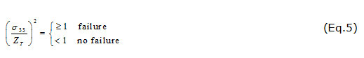
Interlaminar compression failure for σ33 < 0

In the numerical sense, the parameters studied are in close agreement with the convergence of calculations. Hence the advantage of the use of Shell elements and the Hashin criterion, simple geometry and less mesh, no interface between the folds or between the fibers and the matrix.Which gives the advantage to evaluate the location of the defects. These calculations are difficult to support by other numerical methods or criteria applied. The parameters introduced in the ABAQUS calculation code are:
Materials Material, Carbon Epoxy
Damage Initiation, criterion= Hashing 2050. 1200. 62.190. 81., 81.
Damage Evolution, type=Energy 45, 45, 0.6, 0.6.
Damage Stabilization 0.003,0.003,0.003,0.003
Elastic, type=Engineering Constants 170000,9000,9000, 0.34, 0.34, 0.34,4800,4800,4500.
Description of Model Geometry and Material Properties
Materials used :Carbon Epoxy.
The tubes were manufactured by using an epoxy resin system with fiber types of carbon. mandrel diameter 304.8mm and the winding angle of 45° were selected. The mandrel is supported horizontally between a head and a tail stroke. The tail stroke is driven by required angle and speed using computer program. As the mandrel rotates, a carriage moves along the mandrel and give a fiber with a given position and tension. Carriage motion is controlled by the computer Figure.1 repress the process of manufacturing composite tube using filament winding process.
 |
Figure 1: Manufacturing Process of Process |
The dimensions of the tubular structure are normalized (21) as illustrated in Figure (2), with a diameter of diameter of 304.8 mm and as it is of diameter 4 mm. Elasticity and resistance are reported in Table 1, the length of straight pipes on which on the interaction of defects and Lpipe = 1000mm. The length is sufficient to verify that the interference has been constrained or managed in the areas where it has been fixed and charged. The damage is from the default of two adjacent vices in order to release the terminations for these remain pending, they have simply been transferred. Numerically the bending moment on the pipe was obtained by imposing a rotation around the cross section of the pipe and in the plane (XZ).
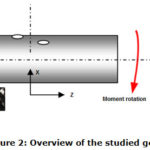 |
Figure 2: Overview of the studied geometry. |
In these three cases of Figure 2, to better compare these structures, a single elliptic shape of two defaults with a single dimension is taken for the different locations. The pipelines are uniformly subjected to an imposed rotation of 1 radian in the plane (XZ). And according to each case at different internal pressures applied. The defects in the three cases studied, their approximations and the distance between them are relative to mid length of the tube.
 |
Figure 3: Schematic representation of localization defaults in (a) opposite move. (b) one fixed and one move and (c) simultaneously move. |
The effect of the interaction of the defects on the damage of the structure took place in this work. Figure.3 presents three situations studied; (a) the two faults take several opposite positions, (b) a single fixed fault and the other takes several positions, (c) the two faults take several positions at the same time. For all the different locations, the defects are around the circumference of the pipe with angular steps of 10 ° and following the longitudinal with steps of 20 mm.
Table 1: Properties of the carbon/ epoxy.
|
Symbol |
Meaning |
Carbon/epoxy |
|
E1 |
Young’ modulus along direction 1 |
170000MPa |
|
E2 |
Young’ modulus along direction 2 |
9000 MPa |
|
E3 |
Young’ modulus along direction 3 |
9000 MPa |
|
ν12 |
Poisson ration in 1-2 plane |
0.342 |
|
ν13 |
Poisson ration in 1-3 plane |
0.342 |
|
ν23 |
Poisson ration in 2-3 plane |
0.542 |
|
G12 |
Shear modulus in 1-2 plane |
4800 MPa |
|
G13 |
Shear modulus in 1-3 plane |
4800 MPa |
|
G23 |
Shear modulus in 2-3 plane |
4500 MPa |
|
XT |
Longitudinal Tensile failure stress |
2050 MPa |
|
XC |
Longitudinal compressive failure stress |
1200 MPa |
|
SL |
Longitudinal shear strength |
81 |
|
YT |
Transverse Tensile failure stress |
62 |
|
YC |
Transverse compressive failure stress |
190 |
|
ST |
Compressive shear strength |
81 |
For all the situations studied, the boundary conditions are as follows: the fixation at the end of the tube of the three displacements along x, y and z. For the opposite part to the edge of the tube, a rotation of the cross section in the opening direction and in the plane (XZ) until their damage, this will be locally caused by the presence of defects. It is reported that all situations studied are under pressure. We use the same experimental properties as those used by Auwal Muhammad (3), that of stiffness and damage of an epoxy carbon composite which is characterized by its architecture: a 45° -fold cross-fiber orientation and with a helical advance along the longitudinal pipe. We give the advantage of using them to analyze the damage by the presence of defects given the difficulty of the architecture of this composite.
 |
Figure 4: Detail of the mesh of region in structure. |
In this analysis, the mesh structure is refined around the area surrounding the two defects and takes several positions, in order to better capture the area of damage in a precise manner. Composite behavior was presented using Schell S4R elements. The number of elements used in the structure is identical for all cases studied with a number of 10699 elements. Figure 4 shows a detail of the mesh used for the calculations.
Results and Analysis
For selected dimensions of defects and the accumulation of compressive loads and bending moment, pipe damage is quickly promoted. The quality and location of defects condition the level and mode of localized damage. Our problem in this work is to clearly identify the effect of the interaction between the defects in the different locations. Only one quality of the defects is taken in the calculation; firstly these dimensions (a / b) = (10/20) mm, secondly the defect is the whole thickness. Numerically this consists of the cancellation of the continuity of the fibers by a significant decrease in these values of rigidity and resistance. This modality of numerical computation gives us the advantage with reliability to create the defects in geometrical situations and of complex loading without there is a problem of convergence.
Effect of the Pressure and Relative Transversal Position Between Defaults on the Failure of Structure
The studied parameters such as the pressure and the relative location of the defects are so interrelated. On the one hand, the defects weaken the structure by their locations in the critical areas and on the other side; the pressure amplifies differently the damage of the structure. Given the architecture of the composite used and the geometrical conditions of the structure, the effect of the interaction between the defects is made only by their relative location by fixing a single quality of defects, the most dangerous one along the whole thickness so to cause substantially damage.
 |
Figure 5: Damage correlation of moment and relative transversal position of defaults spaced longitudinally of 70 mm in the pipeline structure pressured and loaded under flexure moment. |
Figure 5 shows a correlation between the moments at which the structure is damaged and the relative location of the two defects along the transverse with a longitudinal spacing of 70 mm, for internal pressures of 40, 60and 80 bars. It is clearly shown that damage to the composite pipeline under the combined load (flexural pressure) is very sensitive to the location of defects between them; each transverse relative location has its own degree of danger. Their level of damage is much more conditioned by the location of the two defects than by the effect of internal pressure. The internal pressure delays damage by the resistance of the pipe to ovalization, which is reasoned with the presence of defects the non-proportionality of the resistance of the pipeline with the value of internal pressure applied.
It is also noted after the comparison that: the two defects in one occupies a fixed position and the other variant in the transverse is the least dangerous at the other relative locations. The resistance of the pipe in the case (Figure 5) does not exceed a moment of 3.5 KN.m, these maximum values are recorded in the angle positions of 70 ° and 140 ° for 60 bar and 80 bar and 100 ° to 120 ° for 60 bar. The other relative positions that are dangerous between the two defects are recorded in each pressure level applied in the angle of 40 ° up to 60 ° and also at the level of 140 °. In these areas and by the combined effects of internal pressure and bending moment, the fibers of the composite are subjected to critical stresses. On one side the bending cause’s ovalization of the pipeline and on the other, the pressure opposes this ovalization. We also note that in the case where the two defects occupy the same transverse positions, the pressure effect is relatively low and remains dominated by the accumulated effect of the two defects.
Effect of the Relative Longitudinal Position Between Defaults on the Failure of Structure
In this part of our study, our work focuses on the level of the moment of damage under the presence of the internal pressure and under the interaction of two defects with different relative locations, that along the longitudinal and transverse lines of the pipeline. Following the longitudinal, the three spacings between the two defects were taken with a pitch of 20 mm, and following the transverse by three conditions and a pitch of 20 °. First, the two faults move simultaneously, secondly one fixed and the other movable, and thirdly both move inversely. The composite used in architecture and under the presence of defects causes multimodal and localized damage. The defect has taken throughout this study a single form with a single dimension of (a / b) = (10/20) mm, in its region was presented by a low resistance to damage hence its effect to quickly promote the damage of the structure according to the different cases of location selected previously.
 |
Figure 6: Haschin damage representation in structure with two adjacent defaults in the position of 0°. |
Figure 6 shows a correlation between the moment at which the structure is damaged and the relative location of a fixed defect and the other variant according to the transverse and for three longitudinal spacing chosen between the two defects. The resistance capability of the pipeline clearly follows the location of the defects. The internal pressure has always played the role of avoiding the ovalization of the pipeline, from 0 ° to 180 °, the pipeline is subjected to a slight compression, the effect of the defects are very weak when their longitudinal spacing are important. But in the range of 0 ° to 180 ° the damage is very sensitive to the transverse as well as longitudinal location. When the two defects move transversely or are between the planes of application of the bending moment, their effects become very weak, the closer they are, the more they behave like one and the same great defect.
 |
Figure 7: Damage correlation of moment and relative position in the case of,1/ one default fixe and other moving transversally, 2/ two defaults moving transversally and 3/ two defaults opposite moving transversally. |
The following Figure 7 shows a correlation between the moment of structure damage and the relative location of defects, with two adjacent defects varying across the transverse and for the three longitudinal spacing selected from each other at different levels. The causes of the damage are multiple; the figure shows the interdependence of two major effects of transverse and longitudinal displacement that are amplified by the bending moment applied. The strength of the structure is weakened by the presence of defects, causing twisting moments between them. We note that the interaction effect of the two defects on the values of the damage are close together for 50mm and 70mm between 0 ° and 40 ° and between 140 ° and 180 °, and are also close together for 30mm and 70mm between 70 ° and 120 °.
This Figure 6 shows a correlation between the moment at which the structure is damaged and the relative location of the two defects varying transversely in the opposite direction with respect to the vertical plane of the application of the bending moment. They are also presented by three longitudinal spacings selected from each other in order to identify and compare the effect of the relative locations of the two defects. The effect of the location presented in this figure follows the same nature of correlation with levels and areas slightly offset between them. By contribution to the other transversal locations the effect in this case is relatively small. Due to the longitudinal location, the transverse relative locations or the structure is less resistant are recorded between 20 ° up to 60 ° and from 140 ° up to 160 °. These areas cause oblique twists on the pipeline. This quickly causes their damage.
Conclusion
Despite the numerical complications of this work the studied model such as: geometric conditions and complex loading (combined flexion with internal pressure) and in fabric composite and geometrically tubular structures, the criterion of damage has well presented are efficiency, with Schell element, HASCHIN criteria technique has been used to estimate the critical moment value of composite pipeline structure under combined loading. The results obtained allowed us to have an understanding on the interaction of the defects and to compare the different parameters influencing the damage of our studied structure.
Damage in pressurized tubular composite structures can withstand the same loading with different deformation capacity,On the other hand the damage by the presence of defect is aggravated more by their number and according to the loading mode applied. In the tubular structures, the internal pressure opposes the ovalization during loading in bending moment, and conditions its capacity of resistance. However the affability of the structure caused by the relative positioning of defects determines the angle of ovalization.
The oblique torsions in this architecture of the composite quickly promote the damage of the pipeline.
Under the conditions of the studied structure, the effect of the relative location between the defects can go up to 300Nm
Acknowledgments
The work is included in the PRFU 2018 PROJECT under contract B00L02UN310220180011 www.mesrs.dz
References
- Lui, Y.; Shao,X; Zhao,Y.; Qu,L. J.Gas.Oil.App.2009, 361, 1863-1873
- Frost, S.R.; Cervenka, A. J.Com. Man. 1994, 5, 2, 73-81
CrossRef - Auwal, M.; Şevkat,E.J. App. Phy. 2014, 6,30-37
CrossRef - 4.Lemaître ,J.; Chaboche ,J.L.Méc .mat . sol. 2ème édition.1988
- 5.Lachaud,F.; Michel, L.J.Méc. Ind. Mat. 1997, 50, 2-26
- Lee, S. H.; Wass, A. M. J. Frac.1999 ,100, 275 – 306
CrossRef - Palanivelu,S.; Paepegem, W.;Degrieck , J.; Vantomme, J.; Kakogiannis, D.; Ackeren, J.; Hemelrijik, D.; Wastiels ,J.J. Com.Str. 2011, 93,992 – 1007.
CrossRef - Kim, S. H.; Park,C. H.J.Ind.Cro.Pro. 2017,95,651–663
CrossRef - Andersons,J.;König ,M. J. Com .Sci .Tec.2004, 64, 39-52
CrossRef - Xia, M.; Takayanagi, H.; Kemmochi, K.J .Com. Str .2002, 56, 201-210
CrossRef - Xia, M.; Kemmochi ,K.;Takayanagi,H.J. Com Str.2004, 51, 273-283
CrossRef - 12.Soden,P.D.;Kitching,R.;Tse, P.C. J. Com. 1978, 9, 247- 250
CrossRef - 13.Guz, I. A.;Menshykova, M.;Paik , J.K. J. Shi O.ffsh .Str.2015,56,126-136
- 14.Kuang, Y.;Morozov,E.V.; Ashraf, M.A.; Shankar,K. J. Com. Str. 2015, 131, 453-461
CrossRef - 15.Hossain,R.; Carey,J.; Mertiny,P. J Pre Ves .Tec, 2013, 135,1-7
CrossRef - Tsai,S.W.; Wu,E.M. J .Comp. Mat.1971, 5, 58-80
CrossRef - Xia,M.;Takayanagi,H.; Kemmochi ,K. J .Com. Str, 2001, 53, 483-491
CrossRef - Lee,S. H.; Wass,A. M. Int .J. Fra. 1999,100, 275 – 306
CrossRef - Ocheleski, S.; Gotowicki, P. J .Com. Str. 2005,70, 215 – 224.
- ABAQUS user manuals, (Vol. 1 – 3, 2014).
- The American Society of Mechanical Engineers, “Pipeline Transportation Systems for Liquid Hydrocarbons and other Liquids, ASME.B31.4, 1998 Edition.

This work is licensed under a Creative Commons Attribution 4.0 International License.
About The Author
![]()
A New Edition of Web of Science
Journal Impact Factor
2022: 0.5
Five Year: 0.8
Journal is Indexed in

Cabells Whitelist
![]()


