An Efficient Electrochemical Approach for Characterization of the Interface Strength of Nano Titania-Silica (TS) Composite Coating on Titanium Implants
Suja Mathai
Department of Chemistry, Mar Ivanios College, Nalanchira, Thiruvananthapuram, Kerala-695 015, India.
Corresponding Author E-mail: sujamathaikunnath@gmail.com
DOI : http://dx.doi.org/10.13005/ojc/3404060
Article Received on : 16-01-2018
Article Accepted on : 31-07-2018
Article Published : 26 Aug 2018
Biomimetic Growth; Electrochemical Characterization; Titania-silica Composite Coating; Titanium Implants
Download this article as:| Copy the following to cite this article: Mathai S. An Efficient Electrochemical Approach for Characterization of the Interface Strength of Nano Titania-Silica (TS) Composite Coating on Titanium Implants. Orient J Chem 2018;34(4). |
| Copy the following to cite this URL: Mathai S. An Efficient Electrochemical Approach for Characterization of the Interface Strength of Nano Titania-Silica (TS) Composite Coating on Titanium Implants. Orient J Chem 2018;34(4). Available from: http://www.orientjchem.org/?p=48737 |
Introduction
The magnitude of molecular and cellular events at the tissue-implant interface are controlled by the bioactivity and topography of the biomaterial surface.1 Bioactive nano-structured coatings applied on an orthopaedic implant can mimics the properties of a physiological bone.1,2 In the work of Liu X et al. it was mentioned that CaP precipitation can be more easily induced by a nano TiO2 surface than a conventional TiO2 surface.3 The hydroxyapatite (Hap) crystals thus formed on these bioactive coatings in body environment has a crystallographic matches with that of bone apatite crystals.4 These nano TiO2 particles can be coated on to metallic implants by plasma spraying. In plasma-sprayed coatings, difficulties such as maintaining phase purity and mechanical strength in vivo, have been encountered.5,6 It was reported that, a nano TiO2 pre layered-HAp coating showed more adhesion and bioactivity than the single HAp coating on Ti in simulated body fluid (SBF).
The present study focuses on the development of a nano TScomposite coating by a comparatively low temperature thermal decomposition process and its further evaluations under different aggressive and simulated conditions to establish the mechanical, biochemical and biological characteristics including non-cytotoxicity. There was a view of using the implants without any alkaline treatment before biomimetic apatite growth study, so that high bone bonding could be predicted.
Experimental
The SiO2 nano powders were added on to TiCl4/isopropanol solutions and its composition was optimized. A thin layer of the TiCl4/isopropanol+SiO2 was applied on a pretreated Ti substrate and was subjected to continuous heating in a furnace at 500°C for an hour.6 Bio-electrochemical behaviour of these TS composite coatings were compared with that of the TiO2 coatings developed by the same process. A Vicker’s microhardness indenter used to measure the microhardness of these coatings. A maximum load was applied till the coating became flake off. The degradation characteristics of the developed coatings on Ti in 9% NaCl solution, i.e., 9 times concentration of normal physiological solution and in Kokubo’s simulated body fluid (SBF)8 under normal and accelerated conditions, i.e., applying external current densities, were studied. Cyclic polarization study was also done to assess the coating stability. The degradation characteristics of the coatings were further analyzed by EIS measurement. Surface morphology of the coatings was analyzed by SEM and optical microscopy. The chemical analysis of the SBF solutions before and after polarization studies were done by ICP-AES.
The biomimetic growth characteristics of the coatings were studied by immersing in Kokubo’s SBF for 2 weeks at 36.5°C. The topographic analysis of the coatings was carried out by AFM and SEM techniques. The elemental analysis was done by EDS. EIS studies were also carried out to compare the apatite growth characteristics of both TiO2 and TS composite coatings on Ti.
An in vitro cytotoxicity test was performed for both TiO2 and TS composite coatings on Ti using direct contact method as per ISO 10993-5. An ultra high molecular weight poly ethylene (UHMWPE) and poly vinyl chloride (PVC) were used as negative and positive controls respectively. The test samples, negative controls were placed on a subconfluent monolayer of L-929 mouse fibroblast cells. After incubation of the cells with test samples at 37 + 2°C for 24 + 1h, the cell culture was examined microscopically for any
Results and Discussion
The most important property required for a composite coating on a metallic implant for orthopaedic applications is its mechanical stability. Fig. 1 shows the micro-hardness data of both TiO2 and TS composite coatings under various applied loads.
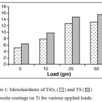 |
Figure 1: Microhardness of TiO2 and TS composite coatings on Ti for various applied loads. Click here to View figure |
The micro-hardness values were found increased with increase in the applied loads. The nano TS composite coating exhibited higher micro-hardness values than the nano TiO2 coating throughout the tests under all the different loads applied. These coatings were stable up to an applied load of 50 gm. The enhanced mechanical stability of the TS composites were due to the formation of a network layer of Ti-O-Si linkages on the surface of Ti and thereby has an increase in bonding strength of the TiO2 coating with an optimum amount of silica. The nano TiO2 dispersed in a SiO2 matrix have tetrahedral structure, which can serve as active sites for further apatite formation.9
The composite coatings applied on metallic implants used for load bearing applications must have adequate adhesive strength at their interfaces.10 The potential values of both the TiO2 and TS composite coatings on Ti even after subjecting to a current density of 5mA/cm2 for 4 hours in 9% NaCl and also in SBF solutions were found to be remained constant during the entire period. There was a minute shift in the potential from the initial value was observed, i.e., +1.8V. There was no surface blemishing or detachment took place on both the TiO2 and TS composite coatings even after applying a current density of 5mA/cm2 for 4 hours. This was revealed from the optical micrographs as shown in Fig. 2.
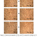 |
Figure 2: Optical micrographs of TiO2 and TS composite coatings on Ti (a) before applying current, (b) after applying a current density of 5mA/cm2 for 4 hours in SBF solution and (c) after applying a current density of 5mA/cm2 for 4 hours in 9% NaCl solution. |
ICP-AES analysis of the 9%NaCl solution, in which degradation study was carried out also confirmed these results that there was 0.00 results obtained for the elemental determination of Ti and Si. OCP variation with time of nano TiO2 and TS composite coatings on Ti in 9% NaCl at 36.5 °C was carried under a current density of 5mA/cm2 for 4 hours. Fig. 3 shows that the initial and final surface potentials remained constant.
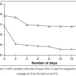 |
Figure 3: OCP variation with time of nano TiO2 (ο) and TS composite (∆) coatings on Ti in 9% NaCl at 36.5°C. |
Table 1: The electrochemical impedance parameters nano TiO2 and TS composite coatings on Ti substrate before and after immersion in 9% NaCl.
|
Sl. No |
Composite coating on Ti substrate |
RpL Ohm |
CpL μF |
RbL kOhm |
CbL pF |
n |
Chi-square |
| (a) | Before immersion in 9% NaCl | ||||||
| 1 | TiO2 | 24.2 | 34.8 | 0.15 | 14.24 | 1.23 | 9.34 |
| 2 | TS | 44.8 | 39.4 | 3.81 | 22.29 | 1.22 | 9.44 |
| (b) | After immersion in 9% NaCl | ||||||
| 3 | TiO2 | 22.2 | 34.8 | 0.14 | 1.00 | 1.26 | 9.69 |
| 4 | TS | 43.6 | 54.1 | 3.66 | 1.00 | 1.26 | 9.69 |
EIS results before and after degradation studies of the coatings is given in Table 1. The resistance values of both the outer porous layer got reduced but not to a considerable extend and therefore a corresponding increase in the capacitance value was observed. ICP-AES results showed that there were no Ti and Si in the physiological solution even after accelerated tests.
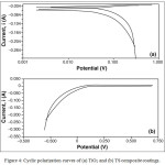 |
Figure 4: Cyclic polarization curves of (a) TiO2 and (b) TS compositecoatings. |
The cyclic polarization curves of both TiO2 and TS composite coatings are presented in Fig. 4. No film breakdown was observed on the samples. After cyclic polarization, both the coatings were found adherent to the substrate. Semi-quantitative analysis by ICP-AES was performed with the 0.9 % NaCl solution in which the cyclic polarization was conducted. No Ti or Si was detected in the solution revealing that there was no degradation of the coating occurred during polarization studies. The native oxide layer of nanometer thickness that already exists on the Ti substrate generates a strong mechanical bond between the TiO2 and SiO2 particles at the interface of the coating.
Fig. 5 shows the AFM image and the line profiles of both the TiO2 and TScomposite coatings prior to immersion in SBF solution describes the surface topography. The line profiles of both TiO2 and TScoatings are found smaller and thinner, showing much smoother surface structures. Rmax (maximum roughness) values obtained for these coatings were 180 and 550 nms respectively.
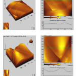 |
Figure 5: AFM – the three dimensional and two dimensional images (including line scan) of (a) TiO2 and (b) TS composite coatings on Ti. |
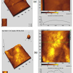 |
Figure 6: AFM – the three dimensional and two dimensional images (including line scan) of (a) TiO2 and (b) TS composite coatings on Ti after immersion in Kokubo’s SBF for 14 days. |
Fig. 6 shows the AFM image and the line profiles of the nano TiO2 and TS composite coatings after biomimetic growth in SBF at pH:7.4 and 36.5°C for 14 days. Rmax values got decreased for both the TiO2 and TS composite coatings due to the formation of crystals of HAp on their surface. The corresponding SEM pictures shown in Fig. 7 also exhibit the presence of white precipitates of HAp on its surface.
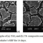 |
Figure 7: SEM micrographs of (a) TiO2 and (b) TS composite coatings on Ti after biomimetic growth in Kokubo’s SBF for 14 days. |
The apatite growth on the surface of both TiO2 and TS composite coatings were also confirmed by EIS results as shown in Table 2. After biomimetic growth the RpL and RbL values got increased, revealing that the increased resistance was offered by the apatite grown on its surface.
Table 2: The electrochemical impedance parameters nano TiO2 and TS composite coatings on Ti substrate before and after biomimetic growth in Kokubo’s SBF for 14 days.
|
Sl. No |
Composite coating on Ti substrate |
RpL Ohm |
CpL nF |
RbL kOhm |
CbL μF |
n |
Chi-square |
|
(a) |
Before biomimetic growth in SBF |
||||||
| 1 | TiO2 |
16.24 |
104.1 |
1.72 |
76.00 |
1.25 |
11.59 |
| 2 | TS |
18.94 |
34.8 |
2.14 |
64.24 |
1.262 |
9.69 |
| (b) | After biomimetic growth in SBF | ||||||
| 3 | TiO2 |
21.91 |
77.2 |
3.94 |
51.20 |
1.02 |
12.56 |
| 4 | TS |
26.11 |
29.59 |
4.83 |
42.3 |
1.01 |
13.3 |
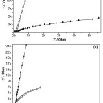 |
Figure 8: Nyquist plots of (a) TiO2 coating (○; before and ●; after) and (b) TScomposite coating (●; before and ○; after) biomimetic growth in Kokubo’s SBF for 14 days. |
Fig. 8 shows the Nyquist plots of the nano TiO2 and TS composite coatings after biomimetic growth in SBF solution at 36.5°C and pH: 7.4 for 14 days. It can also be inferred that more apatite could be induced on the surface due to long term immersion in SBF solution. The TS could be charged negatively in a solution with a physiological pH:7.4 andhence attract the positively charged Ca2+ ions and then PO43- groups in the SBF favoring apatite growth. Apatite nuclei are initiated once, the super saturation rises over the critical level necessary for heterogeneous nucleation of apatite.11-15
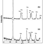 |
Figure 9: XRD patterns of (a) TiO2 and (b) TScomposite coatings. |
The microstructure and crystallinity of TiO2 or SiO2 may be the important factors influencing the nucleation of apatite on the surface.16 XRD patterns of the TiO2 and TS composite coating is shown in Fig. 9. Compared with the standard cards of JCPDS, the major peaks appeared at 2q=37o, 48o and 55o are the peaks of anatase TiO2. The XRD pattern of the TiO2 and TScomposite coatings formed after biomimetic growth in SBF is shown in Fig. 10.
The peaks appeared at 2q=25o, 40o, 45o, and 55o are the characteristic peaks of HAp. The intensity of the HAp peaks got increased and also more peaks of HAp for the TScomposite coatings, which shows its enhanced bioactivity.
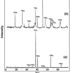 |
Figure 10: XRD patterns of (a) TiO2 and (b) TS composite coatings after biomimetic growth in Kokubo’s SBF for 14 days. |
The developed nano TiO2 and TS crystalline particles have higher surface charge densities17 and readily absorb molecules or ions onto their surfaces in SBF in order to decrease the total free energy and to become more stable.3 It can be further demonstrated by thermodynamic analysis that the interfacial tension also diminishes due to decrease in particle size.18 There is also a crystallographic matching between the apatite (0001) plane and the anatase (110) plane.19 This may lead to higher apatite forming ability of the nano-sized anatase form of the TiO2 particles.
After in vitro cytotoxicity tests, from Fig. 11 it was found that fibroblast cells had grown over the surface of the TScomposite coating on Ti. The fibroblast cells retained its spindle shapes and no rupturing was occurred during incubation of the cells with test samples for 24 + 1 h.
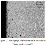 |
Figure 11: Photograph of fibroblast cells around nano TS composite coated Ti. |
Table 3: The results of Qualitative evaluation of in vitro cytotoxicity test.
| Sl. No | Sample | Cytotoxicity scale | Interpretation |
| 1 | Negative control | 0 | Non-cytotoxic |
| 2 | Positive control | 3 | Severely cytotoxic |
| 3 | Sample (TS coated Ti) | 0 | Non-cytotoxic |
Table 3 shows the qualitative evaluation of in vitro cytotoxicity test. Cellular responses were scored as 0, 1, 2, and 3 according to non-cytotoxic, mildly cytotoxic, moderately cytotoxic and severely cytotoxic. The TS coated substrates were found to be non-cytotoxic to the fibroblast cells. Negative controls gave non-cytotxic response while the positive controls gave severely cytotoxic response as expected.
Conclusion
The thermal decomposition process developed in the present work is a viable technique for the formation of TS composite coatings on Ti substrate as a stable network of TSoxide layer is formed during the process. High mechanical stability of the TS compositecoating was revealed by its hardness under various applied loads and it could withstand against an applied load up to 25 gm. There was no degradation on the coating even when it was subjected to different extent of electrochemical polarization and anodic current impression. There were no detachment or decohesion of the coating after polarization. There was no elemental detection of Ti or Si in the physiological solutions after the polarization studies revealing a very good adherence of the TS coating. Hence the present electrochemical approach is found to be worth to analyze the adhesion strength. The results of surface and topographical analysis including SEM and AFM, and elemental analysis of SBF solution revealed an appreciable biomimetic growth character even without any alkaline pre-treatment. These inferences were further supported by the increased resistance values obtained during electrochemical impedance studies. The non-cytotoxic behavior of the TS coated substrate to fibroblasts cells revealed cytocompatiblity. The present nano TiO2 and TS compositecoatings developed on Ti implants by thermal decomposition process can withstand under aggressive body environment conditions and has very good cytocompatibility.
Acknowledgements
The author acknowledges the financial support from UGC, New-Delhi.
References
- Webster, T. J.; Siegel, R. W.; Bizios, R. Biomaterials 1999, 20, 1221.
CrossRef - Ohtsuki, P. Li, C.; Kokubo, T.; Nakanishi, K.; Soga, N.; Groot, de. K. J. Biomed. Mater. Res. 1994, 7, 28.
- Liu, X.; Zhao, X.; Fu, R.K.Y.; Ho, J.R.Y.; Ding, C.; Chu, K.P. Biomaterials 2005, 26, 6143.
CrossRef - Areva, S.; Aaritalo, V.; Tuusa, S.; Jokinen, M.; Linden, M.; Peltola, T. J Mater. Sci.
Mater. Med 2007, 18, 1633.
CrossRef - Milella, E.; Cosentino, F.; Licciulli, A.; Massaro, C. Biomaterials 2001, 22, 1425.
CrossRef - Shibli, S.M.A.; Mathai, S. J. Mater. Sci. Mater. Med. 2008, 19, 2971.
CrossRef - Lin, C.M.; Yen, S.K. J. Mater. Sci. Mater. Med. 2005, 16, 889.
CrossRef - Kokubo, T.; Takadama, H. Biomaterials 2006, 27, 2907.
CrossRef - Sun, D.; Huang, Y.; Han, B.; Yang, G. Langmuir 2006, 22, 4793.
CrossRef - Morks, M.F. J. Mech. Behav. of Biomed. Mater. 2008, 1, 105.
CrossRef - Jokinen, M.; Patsi, M.; Rahiala, H.; Peltola, T.; Ritala, M.; Rosenholm, J. B. J. Biomed. Mater. Res. 1998, 42, 295.
CrossRef - Li, P.; Kangasniemi, I.; Groot, de, K. J. Am. Ceram. Soc. 1994, 77, 1307.
CrossRef - Corbridge, D.E.C. The structural chemistry of phosphorus. Elsevier, Amsterdam-London –New York 1984.
- Shou, G.; Dong, L.; Liu, Z.; Cheng, K.; Weng, W. ACS Biomater. Sci. & Engg. 2017, 6, 875.
CrossRef - Guo, Y.; Tan, Y.; Liu, Y.; Liu, S.; Zhou, R.; Tang, H. Mater. Sci. & Engg.: C 2017, 80, 197.
CrossRef - Ishizawa, H.; Ogino, M. J. Biomed. Mater. Res. 1995, 29, 1071.
CrossRef - Vayssieres, L.; Chaneac, C.; Trone, E.; Joliver, J.P.; J. Colloid Interface Sci. 1998, 205, 205.
CrossRef - Zhang, H.; Penn, R. L.; Hamers, R. J.; Banfield, J. F. J. Phys. Chem. B 1999, 103, 4656.
CrossRef - Uchida, M.; Kim, H.M.; Kokubo, T.; Fujibayashi, S.; Nakamura, T. J. Biomed. Mater. Res. Part B: 2003, 64A, 164.
CrossRef

This work is licensed under a Creative Commons Attribution 4.0 International License.
About The Author
![]()
A New Edition of Web of Science
Journal Impact Factor
2022: 0.5
Five Year: 0.8
Journal is Indexed in

Cabells Whitelist
![]()


