Microstructure Characterization of Natural Magnetite from Sand Marina Beach By High Energy Milling
Sriatun , A. Darmawan, Sriyanti and W. Cahyani
Department of Chemistry, Diponegoro University, Semarang 50275, Central of Java, Indonesia.
Corresponding Author E-mail: sriatun@live.undip.ac.id
DOI : http://dx.doi.org/10.13005/ojc/340234
Article Received on : December 18, 2017
Article Accepted on : January 25, 2018
In this work, we performed an experimental investigation the change of microstructure of magnetite by high energy milling-3D (HEM-3D) method using planetary ball milling at 400 rpm speed. The present studies mainly focusses on the effect of milling on crystallinity and phase of magnetite by XRD, particle size by PSA and the morphology by SEM. The increasing of the ball mass in the milling process, mass ratio magnetite: ball (P/B) 1: 1, 1: 3 and 1: 5 give the magnetite particles smaller (<1μm), the crystallinity decreases but the peaks at (220), (311), (400), (511), and (440) were keep appearing. This shows that the phase of cubic spinel does not change. Rising the milling time for 1 h, 3 h and 5 h can lead to decreasing of size and crystallinity. Even milling time for 5 hours on mass ratio of magnetite: ball (P/B) 1: 5 causes the magnetite phase to change to amorphous.
KEYWORDS:Microstructure; Natural Magnetite; Sand Marina Beach; High Energy Milling-3D
Download this article as:| Copy the following to cite this article: Sriatun S, Darmawan A, Sriyanti S, Cahyani W. Microstructure Characterization of Natural Magnetite from Sand Marina Beach By High Energy Milling. Orient J Chem 2018;34(2). |
| Copy the following to cite this URL: Sriatun S, Darmawan A, Sriyanti S, Cahyani W. Microstructure Characterization of Natural Magnetite from Sand Marina Beach By High Energy Milling. Orient J Chem 2018;34(2). Available from: http://www.orientjchem.org/?p=44592 |
Introduction
Iron sand occurs naturally in several regions throughout the world. Iron sand is one of Indonesia’s natural mineral resources, which is spread over the islands along the coast of Java Island, Kalimantan and Sumatra. Iron sand is a special type of sand that’s rich in the metal iron, the color is dark gray or black, consisting of Fe (iron) as a major element and a small amount of Ti, Si, Ca, Mn and V. They provide a raw material of relatively low grade, whereas in the southern coast of Yogyakarta containing 5.85 % to 95.11% of iron. In addition to magnetite in iron sand also contains other minerals such as rutile, ilmenite and hematite [1]. While most sand contains at least some trace of iron, therefore it has a distinct dark-gray or black color, which is in stark contrast to the white-yellow color of regular sand. Iron sand is a magnetic material that is widely used in various fields such as electronics, energy, chemistry, ferrofluidics, catalysts, and medical diagnostics [2]. The application of iron sand was inseparable from the development of studies of nanomaterials demanding that they be in the order of nanometers. Magnetite or Fe3O4 is one of the iron oxide phases which has the greatest magnetic or ferromagnetic properties among the other phases. Iron oxide has four phases, namely magnetite (Fe3O4), maghemite (γ-Fe2O3), hematite (α-Fe2O3), and geotite (FeO(OH)). Only magnetite and maghemite have magnetic properties [3]. Magnetite (Fe3O4) is known as a class of iron oxide compound with a cubic inverse spinel structure and has face centered cubic close packed oxygen anions and Fe cations occupying interstitial tetrahedral and octahedral sites [4, 5]. Nano-sized magnetite particles provide many advantages such as for the separation of magnetic contaminants in water, large of surface area and the ability to bind through electro-chemical interactions to form sludge. It is also applied to drug delivery and magnetic resonance technology and others. For the synthesis of nanosized magnetite particles can be synthesized through various methods such as mechanical milling [6], sol-gels, direct decomposition [7], co-precipitation [8], microwave-heating [9] and solvothermal [10, 11]. Mechanical milling method is one way to reduce the magnetite size is the cheapest and easy. Mechanical milling is defined as the mechanical breakdown of magnetite into smaller without changing their state of aggregation. The method was used to increase the surface area and induce defects which is needed for subsequent operations such as chemical reactions, sorption. Milling also to increase the proportion of regions of high activity in the surface [12]. Furthermore, this research the small size of magnetite from iron sand was prepared by mechanical milling method using high energy planetary ball mill. Kinetic energy of the balls depends not only on its velocity, but also on its mass and how long the collision occurred, due to in this work investigated the ratio of magnetite and ball mass in the planetary ball mill and the time of impact during collision.
Materials and Methods
Materials
Iron sand was taken from Marina Beach in Semarang.
Instrumentations
Magnet permanent, High energy planetary ball mill-3D, X-ray diffraction (XRD) Rigaku Multiplex with Cu Kα radiation (λ = 1.54184 Ao) at generator voltage 40 kV and current 40 mA, Particle Size Analyzer (PSA) Horiba SZ-100, Scanning electron microscope (SEM) JEOL JED 2300.
Procedure Magnetite preparation
The natural iron sand from Marina Beach Semarang cleaned and washed using aquadest, dried in oven at 80oC for 24 hours. Natural magnetite was extracted from natural iron sand using permanent magnet until 12 times. This treatment produces powder material dark gray-black color. Refinement of magnetite particles carried out by mechanical milling method using High Energy planetary ball Mill (HEM-E3D) instrument. The milling was done on mass ratio of magnetite: ball (P/B) 1:1, 1:3 and 1:5, speed 400 rpm. Milling of magnetite carried out for 1, 3 and 5 hours. Milled magnetite dried at 150oC for 1.5 hours. Finally, the microstructure characterization of product was done by X-ray Diffraction (XRD) to find out the structure of magnetite crystals, PSA to determine the size of magnetite particle, SEM to know the surface morphology.
Results and Discussions
In this work the change of crystal structure, particle size and morphology of magnetite to be investigated. The method is high energy milling (HEM) used planetary ball mill. The choice of this method due to it can reduce the material up to the nano order (nano particle) inside a relatively short time under conditions atmosphere at room temperature during process milling. This method using energy collision between the crushing balls and chamber walls are rotated and driven in a certain way. The change of crystal structure, particle size and morphology of magnetite was studied on variation the mass ratio magnetite:ball (P/B 1:1, 1:3 and 1:5) and milling time (1, 3 and 5 hours).
Physical Changes of Magnetite
The process of separation of magnetite compounds from iron sand is done repeatedly, it is intended that the compound to be obtained has a high purity. The separation process with magnets also uses a certain distance, the farther the magnet is closer to the iron sands, the less iron oxide attaches. This makes the sample (magnetite) higher purity and less impurities, although there is still the possibility of the other oxide compounds sticked to a permanent magnet. The Fig. 1 following is the embodiment of magnetite extracted from iron sand.
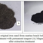 |
Figure 1: The original iron sand from marina beach before extraction treatment with permanent magnet (A) Magnetite after extraction treatment Click here to View figure |
The extracted iron sand powder then performed mechanical milling with several variations of the mass ratio of magnetite:ball (P/B) 1:1, 1:3 and 1:5 for 1, 3 and 5 hours at speed 400 rpm. Magnetite obtained from the milling results has a softer texture and dark black as shown in Fig.2.
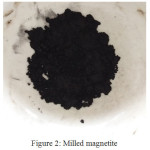 |
Figure 2: Milled magnetite |
It is clearly from Fig. 1A and 1B and Fig 2, the difference in color and size of iron sand. In iron sand that has been separated with permanent magnet looks blacker than iron sand that has not been separated. This is due to the reduction of impurities from the iron sand so that the iron sand look blacker after extraction using permanent magnet as much 12 times. This shows that the separation of iron sand from impurity elements by this method more effectively. The size of iron sand after mechanical milling becomes smaller and softer than the separated iron sand. This is the advantages of mechanical milling method that ball mill is not sensitive to metal. The superiority of High Energy Milling is able to produce smaller particles in shorter milling time [12].
Crystal Structure of Magnetite
Based on the results of the analysis using X-ray diffraction on magnetite powder before milling treatment with HEM-3D obtained X-ray diffraction pattern as shown in Fig. 3. There are five highest peaks at 2θ angle of 30.09º; 35.46º; 43.09º; 56.98º; and 62.59º. Furthermore the highest peaks were compared with Joint Committee of Powder Diffraction Standard (JCPDS) number 89-4319 with the highest peaks at 2θ angle of 30.083º; 35.434º; 43.064º; 56.949º; and 62.536º. Based on data obtained from XRD, the compound is magnetite.
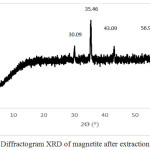 |
Figure 3: Diffractogram XRD of magnetite after extraction treatment |
Data of X-ray diffraction on magnetite after HEM-3D treatment with mass ratio of magnetite:ball (P/B) 1: 1, 1: 3 and 1: 5 and time collision 1, 3 and 5 hours showed in Fig. 4, Fig.5 and Fig. 6. All diffraction peaks correspond to the peak diffraction at (2 2 0), (3 1 1), (4 0 0), (5 1 1), and (4 4 0). Of the highest peaks are compared with the Joint Committee of Powder Diffraction Standard (JCPDS) number. 79-0418 shows indexed to the Fe3O4 cubic spinel phase.
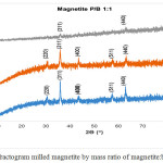 |
Figure 4: Diffractogram milled magnetite by mass ratio of magnetite:ball (P/B) 1:1 |
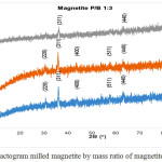 |
Figure 5: Diffractogram milled magnetite by mass ratio of magnetite:ball (P/B) 1:3 Click here to View figure |
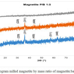 |
Figure 6: Diffractogram milled magnetite by mass ratio of magnetite:ball (P/B) 1:5 |
The XRD datas show that in all P / B ratio 1, 1: 1: 3 or 1: 5 with milling process for 1 and 3 hours still indicates conformity with reference magnetite. When the milling for 5 hours is only in P/B 1: 1 and P/B 1: 3 which still shows the suitability and even this is only at the peak of 2Ɵ = 35.92o and 63.02o at P/B 1: 1 and 36.19o and 63.15o at P/B 1: 3, where the peak of the diffractogram is very low, whereas in P/B 1: 5 there is no correspondence with the reference magnetite. This suggests that long-term milling treatments and strong collisions (heavier ball) can significantly reduce magnetic particle size, these treatments also decreased degrade of crystallinity. The increasing of ball to magnetite mass ratio (heavier ball) would enhancing the kinetic energy during milling. Based on kinetic energy equation:
![]()
In which Ek is the kinetic energy, m and v are respectively the mass and velocity of the balls. In this research the velocity was constant. When the colliding ball mass is heavier, so the kinetic energy increases. The high of kinetic energy would cause the particles to collide with each other, where this would decrease in particle size. This is in accordance with data that has been revealed by previous research. It was reported that the enhancing energy during milling, resulted by the increase of ball to powder weight ratio (BPR) and vial speed not only can accelerate the formation of the products but also changes the resultant phases [4]. The balls play an important role in its efficiency so that a small change in type, shape, weight or mass and size distribution of the balls can dramatically affect the milling process [5]. The increase of the number of balls at high BPR ratio, has a quite negative effect on the milling performance [6].
Particle size of magnetite
This matter proves that the milling process is done to magnetite powder can causing the destruction of the grains magnetite powder as a result collision between magnetite powder and milling balls. To know more clearly destruction of graphite powder during process milling, then the measurement magnetite particles by particle size analyzer (PSA) instrument. The choice of particle measurement methods of nanoscale and micro size is usually by using a wet method PSA (particle size analyzer) method, because it is an accurate method when compared to other methods. Small particles have a tendency for high agglomeration, the choice of wet method on PSA because the particles are dispersed into the medium so that the particles do not agglomerate (clump). Therefore the measured particle size is the size of a single particle and provides overall information on sample conditions. Distribution particle size test by particle size analyzer (PSA) aims to determine particle size distribution after mechanical milling process by HEM-3D for 1 hour, 3 hours and 5 hours. The result of milled magnetite can be seen in Fig. 7.
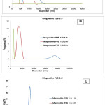 |
Figure 7: Graph of magnetite size distribution on mass ratio magnetite:ball (P/B) 1: 1 (A); 1: 3 (B) and 1: 5 (C) |
In Fig. 7 it is observed that the magnetite/ball mass ratio (P/B) of 1: 1 increase in time causes a significant reduction in particle size. When for 1 hour milling the size range varies as well as for 3 h, however the milling is performed for 5 hours gives impact to a more homogeneous magnetite size (the peak is not widened). Significant reduction in size occurred in treatment with a mass ratio of P/B 1: 3 and 1: 5. This is due to the heavier the ball and the length of time the greater the energy given to collide with the magnetite particles. Thus the magnetite treatment with HEM (high energy milling) is effective enough to reduce the size to less than 1000 nm (<1μm).
Morphology of Magnetite
The surface morphology of a material can be observed using SEM (Scanning electron microscope). The basic principle of work on SEM is the nature of electron waves, it is diffraction at very small angles. Electrons are dissipated by a charged sample. The image formation on SEM comes from the electron beam reflected by the sample surface. If the sample used is not conductive, the sample must first be coated with gold [16]. Based on the SEM image in Fig. 8, the addition of spherical periods has an effect on the reduction of natural magnetite particle size. In the P/B ratio 1: 1 the particle size varies from small to large size. When the mass of balls increase 3 times to magnetite (P/B 1: 3), the collision between the magnetite and the ball gets stronger or the greater the energy that causes the breaking of the particles to become smaller and appear more homogeneous. In addition to the ball up to 5 times the magnetite period (P/B 1: 5) the particles also become smaller but the possibility of agglomeration appears to be larger if compared to P/B 1: 3. The size of the magnetite particles is slightly affected by the length of time the collision with the ball on the planetary ball mill. The milling process for 1 to 3 hours gives almost the same result, observed on surface morphology at P/B 1: 1 for 1 hour is almost equal to 3 hours. Similarly to P/B 1: 3 for 1 hour is almost the same as for 3 hours, and P/B 1: 5 for 1 hour with 3 hours. However, when the milling for 5 hours on the three variations of the ball period gives significantly different results with the previous. This is especially observed in P/B 1: 3 for 5 hours, visible particles having clear and firm shape and cleaner than others.
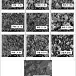 |
Figure 8: Morphology of milled magnetite and initial magnetite by magnification 5000x |
Conclusion
From the results and discussion can be concluded that the HEM-3D treatment with 400 rpm speed can reduce particle size and increase the uniformity of shape and magnetite size. The increasing of the ball mass in the milling process, this means in the mass ratio of magnetite:ball (P/B) 1: 1, 1: 3 and 1: 5 give the magnetite particles smaller, the crystallinity decreases but the phase does not change. Rising the milling time can lead to decreasing of size and crystallinity. Even milling time for 5 hours on mass ratio of magnetite:ball (P/B) 1: 5 causes the magnetite phase to change to amorphous
Acknowledgement
Sriatun, Adi Darmawan and Sriyanti, gratefully acknowledge financial support from of Besides APBN DPA SUKPA LPPM Diponegoro University, and Department of Chemistry for the facilities to carry out this research.
References
- Nugraha, P.A.; Sari, S.P.; Hidayati, W.N.; Dewi,C.R.; Kusuma, D.Y. AIP Conference Proceedings, 2016, 1747 (1)
- Shpotyuk, O.; Bujňáková, Z.; Sayagués, M.J.; Baláž, P.; Ingram, A.; Ya.Shpotyuk, Demchenko, P. Materials Characterization, 2017, 132: 303-311.
CrossRef - Gong, J. Journal Hazardous Mat., 2009, 164:1517-1522
CrossRef - Hui, C.; Shen, C.; Yang, T.; Bao, L.; Tian, J.; Ding, H.; Li, C.; Gao, H.J. J. Phys. Chem. C. 2008, 112, 11336-11339.
CrossRef - Klotz, S.; Steinle-Neumann, G.; Strassle, T.; Philippe, J.; Hansen, T.; Wenzel, M.J. Phys. Rev. B, 2008, 77, 12411-1-1241-4.
- Marinca, T.; Chicinaș, H.; Neamțu, B.; Popa, F.; Isnard, O.; Chicinaș, I. Studia Universitatis Babes-Bolyai, Physica, 2015, 60 (1).
- Darezereshki, E.; Bakhtiari, F.; Alizadeh, M.; Ranjbar, M. Materials Science in Semiconductor Processing, 2012, 15(1): 91-97.
CrossRef - Khan, U.S.; Rahim, A.; Khan, N.; Muhammad, N.; Rehman, F.; Ahmad, K.; Iqbal, J. Materials Chemistry and Physics, 2017, 189: 86-89.
CrossRef - Chikan, V. and McLaurin, E. J. Nanomaterials,2016, 6(5): 85
CrossRef - An,J.S.; Han, W.J.; Choi, H.J. Colloids and Surfaces A: Physicochemical and Engineering Aspects, 2017, 535:16-23
CrossRef - Bui, T.Q.; Ton, S.N.; Duong, A.T.; Tran, H.T. Journal of Science: Advanced Materials and Devices, 2017, Available online 14 November 2017
- Balaz, P. Mechanochemistry in Nanoscience and minerals Engineering, 2008, Springer-Verlag Berlin Heidelberg, 103.
- Bolokang, S., Banganayi, C., Phasha, M. Int. J. Refract. Met. Hard Mater, 2010, 28:211–216.
CrossRef - Zakeri, M., Rahimipour, M.R. Adv. Powder Technol, 2012, 23:31–34
CrossRef - Ghayour, H., Abdellahi , M., Bahmanpour, M. Powder Technology, 2016, 291: 7–13
CrossRef - Prabakaran, K.; Balamurunga, A.; Rajeswari, S. Bull Mat Sci, 2005, 28:115-119.
CrossRef

This work is licensed under a Creative Commons Attribution 4.0 International License.
![]()
A New Edition of Web of Science
Journal Impact Factor
2022: 0.5
Five Year: 0.8
Journal is Indexed in

Cabells Whitelist
![]()


