Three-dimensional free vibration analysis of carbon nanotube reinforced composites annular plates
Hakimeh Zali1, 2, Fatemeh Yazdian3 and Meisam Omidi1, 2
1Research Center for Medical Nano-Technology and Tissue Engineering, School of Advanced Technologies in Medicine, Shahid Beheshti University of Medical sciences, Tehran, Iran
2Department of Tissue Engineering and Regenerative Medicine, School of Advanced Technologies in Medicine, Shahid Beheshti University of Medical sciences, Tehran, Iran
3Faculty of New Science and Technology University of Tehran, Tehran, Iran.
Corresponding author Email: m_omidi@sbmu.ac.ir
DOI : http://dx.doi.org/10.13005/ojc/320249
Article Received on :
Article Accepted on :
Article Published : 11 May 2016
The main objective of this research work was to investigate three-dimensional free vibration of thick annular plates which are composed of carbon nanotube (CNT) reinforced composites materials using the Chebyshev–Ritz method. In order to obtain precise results, a new form of the rule of mixtures including an exponential shape function, length efficiency parameter, orientation efficiency factor, and waviness parameter was applied for predicting the mechanical properties of CNT reinforced composites. Convergence of the Chebyshev–Ritz method was also checked. Numerical results are given and compared with the available literature and finite element method (FEM) analysis. Results obtained from the other well-known theories (such as: Micro-Mechanical, Halpin, etc.) are compared with the new form of the rule of mixtures results. Furthermore, the effects of CNT type, structures, diameter, shape factor, density, and volume fraction on the vibration behavior of the annular plates are graphically presented.
KEYWORDS:Nanocomposites; modified rule of mixtures theory; annular plates; Chebyshev -Ritz method; vibration analysis
Download this article as:| Copy the following to cite this article: Zali H, Yazdian F, Omidi M. Three-dimensional free vibration analysis of carbon nanotube reinforced composites annular plates. Orient J Chem 2016;32(2) |
| Copy the following to cite this URL: Zali H, Yazdian F, Omidi M. Three-dimensional free vibration analysis of carbon nanotube reinforced composites annular plates. Orient J Chem 2016;32(2). Available from: http://www.orientjchem.org/?p=16001 |
Introduction
In recent years astonishing advances in science and technology have motivated researchers to work on new structural materials possessing high strength to weight ratio. Carbon nanotube (CNT) reinforced polymer composites are one of these advanced materials, having many attractive applications in mechanical, chemical, electrical, optical, aeronautics, astronautics, and biomechanical industries.
A review of existing literature on the mechanical properties of CNT reinforced polymer composites demonstrates that many studies have been done recently e.g., 1–11. Significant improvements in mechanical properties of polymeric matrixes have been reported by adding a few weight-percents (wt%) of CNTs.
Although a lot of parameters such as dispersion methods, type of CNTs, weight percentage of CNTs relative to matrix, etc., can affect the mechanical properties of composites; all in all it has been quite evident that added stiffness versus added mass unit is undeniably exceptional, which is very interesting for free vibration analysis. Technically speaking, composites annular plates are widely used in industrial structural elements. There are large number of research papers and reviews on the free vibration analyses of isotropic annular plates 12-19. A few researchers have analyzed vibration and static behavior of nanocomposites plates 20-23.
During the last decade, several research groups have presented theoretical models to predict mechanical properties of CNT reinforced polymer composites. An excellent survey of the research work on the different modeling techniques as proposed for predicting the mechanical behavior of polymer composites has been published by Valavala and Odegard 24. The micromechanical model is one of the renowned methods extensively used to predict elastic properties of CNT/polyimide composites in lot of articles 25-28. Mechanical properties of high density polyethylene composites reinforced with CNTs were presented by Kanagaraj et al. 29. They employed both the Halpin-Tsai model and a modified form of the rule of mixture model to make a comparison between theoretical and experimental results. Bokobza 30 used the Guth and the Halpin-Tsai predictions to compare her experimental values obtained for the Young’s modulus of MWCNTs/elastomeric composites with those predicted by the models. All proposed models (e.g. micromechanical, Halpin-Tsai and rule of mixture) used, for instance, in refs 25-30, are valid only for low wt% of CNTs, where the variation of the Young’s modulus of CNT/polymer composites versus wt% of CNTs is almost linear. However, it is well known that there exists a nonlinear relationship between mechanical properties of CNT/polymer composites and volume fraction of CNTs. According to a comprehensive survey of literature, various authors have found that relatively little work is available on new micromechanics models, enabling us to properly predict the mechanical properties of CNT/polymer composites for both low and high wt% of CNTs. M. Omidi et al. 31 investigated the effect of MWCNT content on the mechanical properties of epoxy composites. They modified the rule of mixture model by introducing a length efficiency parameter, orientation efficiency factor and waviness parameter to the model. This model predicted the mechanical properties of nanocomposites for both low and high wt% of CNTs.
In this paper, a three-dimensional (3-D) free vibration analysis of CNT-reinforced composite annular plates with different combinations of boundary conditions at the inner and outer edges of the annular plate is presented on the basis of the Chebyshev-Ritz method. In order to achieve more reliable and precise results, the mechanical properties of the nanocomposites were obtained through a modified rule of mixtures theory 31. The validity and the range of applicability of the results obtained based on the other well-known theories (such as: Micro-Mechanical, Halpin Tesai and etc.) were studied by comparing them with those obtained by the modified rule of mixtures. Moreover, the influence of the CNT type (single wall or multi wall), structures (zigzag or armchair), diameter, shape factor, density and volume fraction on the frequency parameters of the plate was also studied.
Theoretical formulation
Consider a thick composite annular plate with outer radius, inner radius and thicknesses as depicted in Fig. 1. The plate geometry and dimensions were defined in an orthogonal cylindrical co-ordinate system (r,θ,z).
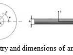 |
Figure 1: Geometry and dimensions of an annular plate Click here to View figure |
Theory of fiber reinforced composite materials
Micromechanical Mori–Tanaka equations
A rather simple and accurate micromechanics method is Mori–Tanaka method 32. It assumes each inclusion in the infinite pristine matrix loaded by an effective stress that equals the average stress over the matrix. The effective moduli of inclusion-dispersed composites may be easily derived with good accuracy even for a high volume fraction of inclusions. For a composite reinforced by nanoparticles, this method leads to the effective Young’s modulus Ec, bulk modulus Kc and shear modulus Gc as:
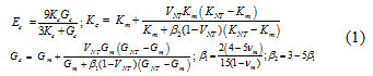
where υm the Poisson’s ratio of the matrix and, K and G denote the bulk modulus and the shear modulus, the subscripts ‘‘m” and ‘‘NT” stand for matrix and nanoparticulate, respectively.
The Halpin-Tsai equations
One of the equations which is frequently used for modeling the mechanical behavior of nanocomposites is the Halpin-Tsai equation which can be written as equation (2).
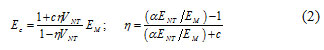
In which c=2(l/d) is a constant shape factor related to the aspect ratio of the reinforcement length l and diameter d. Also, EM , ENT , and VNT are the modulii of matrix, CNT, and the volume fraction of nanotubes, respectively. Parameter α is an orientation factor which was later introduced by Cox 33. For the random oriented in two dimensions α =1/3, and for the random oriented in three dimensions α =1/6.
The rule of mixtures equations
For a composite with uniaxial reinforcement and under constant strain conditions, the dependence of the elastic modulus on the long fiber like CNTs volume fraction can be estimated by the rule-of-mixture as follows:
Ec/M= (K∫ENT/M-1) VNT, (3)
Where EC|M= (Ec-EM)| and ENT|M =ENT|EM- takes a value between 0 and 1, and can be determined by:
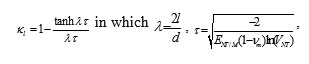
where λ is the CNT aspect ratio. The parameter approaches 1 for large volume fractions of high aspect ratio CNTs.
The modified rule of mixtures theory
According to the experimental data reported in the literature 31-40, when the volume fraction of CNTs takes larger values a nonlinear trend for the elastic modulus can be seen. As a consequence, the new form of the rule of mixtures can be expressed as
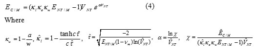
and ÈC|M = (Èc– EM)/EM. Note that each parameter having the hat ^ should experimentally be determined by a tensile test for a given wt% of CNTs. In other words, the value of the parameter α is determined by testing only one tensile CNT composite specimen 31.
Energy and frequency equations
The constituent equation for the circular plate is:
[σ]= {S}[ε] (5)
Where σ, S, and ε represent the stress tensor, compliance tensor, and strain tensor, respectively. Eq. 5 shows the relationship between stress and strain.
For free vibrations, the displacement components of a three-dimensional elastic body may be expressed as:
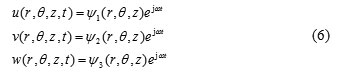
Where t is the time, ω denotes the natural frequency of vibration and j= √-1. Also, u, v, and w are referred to displacement components along the radial, tangential, and axial directions, respectively. ψ1, ψ2 and ψ3 are unknown displacement functions in the r, θ, and z directions, respectively.
Considering the cylindrical symmetry of the circular plate about the coordinate θ, the displacement amplitude functions can be written as:
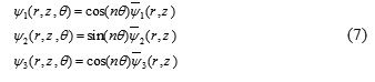
Where the non-negative integer n represents the circumferential wave number of the corresponding mode shape. It is obvious that n=0 leads to an axisymmetric vibration. Rotating the symmetry axes by π/2, another set of free vibration modes can be obtained, corresponding with an interchange between cos (nθ) and sin (nθ) in Eq. (7); however, in such a case, n=0 represents a torsional vibration. is the displacement function in the r and z coordinates.
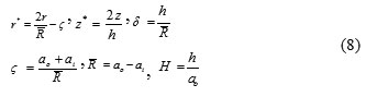
To simplify the equations, the following dimensionless parameters are introduced:
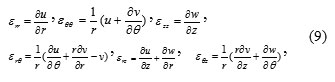
Using the displacement field given in equation (6), the strain components εij (i,j=r,θ,z) for small deformations are defined as follows:
The strain (potential) energy V of a three-dimensional elastic circular plate undergoing free vibration in circumferential coordinates is expressed in terms of the strains (εij) and the stress (σij) as:
![]()
And the kinetic energy for free vibration is:
![]()
The Lagrangian energy functional (Π) of the plate is defined as:
![]()
The displacement amplitude functions may be assumed in the form of a double series of Chebyshev polynomials multiplied by boundary functions as follows:
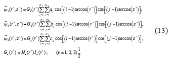
In which aij, bij and cij are the undetermined coefficients; i and j are integers; N1 and N2 are the highest degrees taken in the polynomial terms, and Ge (r*); (e=1, 2, 3) are functions depending upon the geometric boundary conditions to be enforced. It should be emphasized that in the Chebyshev–Ritz method, the displacement functions u, v and w should satisfy the geometric boundary conditions of the plate. The boundary function components in outer edge Ie (r*) and inner edge He (r*); (e=1, 2, 3) of annular plate corresponding to different combinations of boundary conditions.
To obtain natural frequencies, the eigenvalue problem is formulated by minimizing the Lagrangian energy functional with respect to the arbitrary coefficients aij, bij and cij Thus we have:
![]()
which in turn leads to the following eigenfrequency equation in matrix form as:
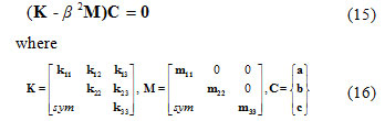
and
is the frequency parameter. Parameter H is plate thickness.
Solving the eigenvalue Eqs. (14)- (16) yield the frequency parameters β.
Numerical results and discussion
The properties of the carbon nanotubes and matrix which were used in this article are presented in Figs. 2 and Table 1.
Table 1: Mechanical properties of the carbon nanotubes and matrix [31]
| Mechanical properties |
SWNTs |
MWNTs |
Matrix (LY-5052) |
| Diameter (nm) |
10 |
25 |
– |
| (GPa) |
1200 |
1000 |
3.11 |
| (GPa) |
6.63 |
15.58 |
3.11 |
| (GPa) |
442 |
320 |
1.2 |
| (GPa) |
17 |
4.1 |
1.2 |
|
0..20 |
0.25 |
0.35 |
|
| (kg/m3) |
1350 |
1250 |
1100 |
According to Fig. 2(a), a strong linear relationship between the nanotube diameter and wall thickness can be observed [39]. From the measurement of inside and outside diameter, the nanotube density per unit length can be calculated by assuming that the graphite layers of the tube shell have the density of fully dense graphite (ρg = 2.25 g/cm3). The nanotube density as a function of diameter is shown in Fig. 2(b), where the curved line is obtained directly from the straight line in Fig. 2(a). The morphology of a carbon nanotube is determined by the orientation and magnitude of the chiral vector in a graphene sheet, which is wrapped up to form the single-walled carbon nanotube (SWCNT). The two configurations are armchair and zigzag nanotubes. The Young’s modulus as function of nanotube diameter, obtained by using molecular structural mechanics (Li and Chou [34]), tight-binding molecular dynamics (Hernandez et al. [35]), and experimental data (Krishnan et al. [37]) are presented in Fig. 2(c). For molecular structural mechanics, the results are sensitive to nanotube diameter and nanotube structure at small diameter. The axial Young’s modulus approaches to 1.03 TPa for diameters 1.0 nm.
Numerical solutions for the 3-D vibration analysis of nanocomposites annular plates for various geometry and boundary condition were computed. The vibration frequency β was expressed in terms of a non-dimensional frequency parameter.
In order to check the stability of the proposed approach as well as to validate the accuracy of that, some convergence tests and comparison studies were performed.
For the convergence study, the first four frequency parameters (e.g. nanocomposite annular plate) of completely free nanocomposites annular plate with inner-outer radius ratio ai/a o= 0.6 different thickness-radius ratio H, κo = 0.2, κw = 0.4, ENT/M = 321.5, C = 2000, α = -11.83, ρNT/M = 1 and MWCNT volume fraction VNT = 0.5% and 4% were performed, with results listed in Table 2. Four groups of series terms were taken into account, as shown in Table 2, where N1 means the number of terms used in the radial direction and N2 means those used in the thickness direction for each displacement component. From the frequency parameters presented in Table 2, it can be observed that when the used terms were set to be N1= 10 and N1= 10 to five significant figures.
![Fig. 2. Variation in: (a) nanotube wall thickness with nanotube diameter and (b) density with nanotube diameter [39]. (c) Diameter sensitivity of elastic modulus predicted by molecular structural mechanics (Li and Chou [34]), tight-binding molecular dynamics (Hernandez et al. [35]) and experimental data (Krishnan et al. [37]).](http://www.orientjchem.org/wp-content/uploads/2016/05/Vol32_No2_Thre_HAKI_Fig2-150x150.jpg) |
Figure 2: Variation in: (a) nanotube wall thickness with nanotube diameter and (b) density with nanotube diameter [39]. (c) Diameter sensitivity of elastic modulus predicted by molecular structural mechanics (Li and Chou [34]), tight-binding molecular dynamics (Hernandez et al. [35]) and experimental data (Krishnan et al. [37]). Click here to View figure |
The three-dimensional free vibrations of a thick annular plate with different boundary conditions, thickness ratio, and inner-outer radius ratio, VNT = 0 and υm = 0.3 are presented in Table 3 together with the published values of Liew and Yang [15] and Hosseini Hashemi et al. [17]. From Table 3, it is found that the present results were in close agreement with both Liew and Yang [15] and Hosseini Hashemi et al. [17].
Table 2: Convergence of the first six frequency parameters of completely free nanocomposites annular plate when κo = 0.2, κw = 0.4, ENT/M = 321.5, C = 2000, α = -11.83, ai/a o= 0.6, ρNT/M = 1
|
H |
VNT |
N1×N2 |
Mode sequence number |
|
||
|
1 |
2 |
3 |
4 |
|||
|
0.1 |
0.5 |
7×7 |
2.4101 |
6.7018 |
6.8045 |
7.8216 |
|
10×10 |
2.4100 |
6.7017 |
6.8045 |
7.8216 |
||
|
14×14 |
2.4100 |
6.7017 |
6.8045 |
7.8216 |
||
|
21×21 |
2.4100 |
6.7017 |
6.8045 |
7.8216 |
||
|
4 |
7×7 |
3.0467 |
8.4727 |
8.6018 |
9.8878 |
|
|
10×10 |
3.0466 |
8.4726 |
8.6018 |
9.8878 |
||
|
14×14 |
3.0466 |
8.4726 |
8.6018 |
9.8878 |
||
|
21×21 |
3.0466 |
8.4726 |
8.6018 |
9.8878 |
||
|
0.4 |
0.5 |
7×7 |
1.6944 |
1.9580 |
3.9905 |
4.2921 |
|
10×10 |
1.6944 |
1.9580 |
3.9905 |
4.2921 |
||
|
14×14 |
1.6944 |
1.9580 |
3.9905 |
4.2921 |
||
|
21×21 |
1.6944 |
1.9580 |
3.9905 |
4.2921 |
||
|
4 |
7×7 |
2.1420 |
2.4754 |
5.0460 |
5.4258 |
|
|
10×10 |
2.1420 |
2.4754 |
5.0460 |
5.4258 |
||
|
14×14 |
2.1420 |
2.4754 |
5.0460 |
5.4258 |
||
|
21×21 |
2.1420 |
2.4754 |
5.0460 |
5.4258 |
||
Figure 3(a) shows comparison of the experimental data and theoretical prediction models for the Young’s modulus of MWCNT/epoxy composites as a function of CNT content [31]. The previous micromechanical models (Micro-Mechanical Mori-Tanaka, Halpin-Tsai method, and rule of mixtures) reported in the literature failed with the increase of the wt% of MWCNTs. Since the frequency parameter is completely depend on the Young’s modulus, the previous micromechanical models (Micro-Mechanical Mori-Tanaka, Halpin-Tsai method, and rule of mixtures) cannot calculate the frequency parameter correctly.
Table 3: Comparison of the first six frequency parameters resulted from the presented study by Liew and Yang [15] and Hosseini Hashemi et al. [17] when VNT = 0 and υ = 0.3
|
H |
ai/a o |
Source of results |
Mode sequence number |
||
|
1 |
2 |
3 |
|||
| An annular plate with both outer and inner edges free (F-F) | |||||
|
0.20 |
0.3 |
Ref a |
2.2079 |
3.7727 |
5.3255 |
|
Authors |
2.2079 |
3.7727 |
5.3255 |
||
|
0.35 |
0.1 |
Ref b |
2.2901 |
3.7086 |
4.8676 |
|
Authors |
2.2901 |
3.7086 |
4.8676 |
||
| An annular plate with simply supported outer edge and free inner edge (S-F) | |||||
|
0.20 |
0.3 |
Ref a |
2.1698 |
5.3719 |
6.0898 |
|
Authors |
2.1698 |
5.3719 |
6.0898 |
||
|
0.35 |
0.1 |
Ref b |
2.1789 |
3.3439 |
5.3938 |
|
Authors |
2.1789 |
3.3439 |
5.3938 |
||
| An annular plate with clamped outer edge and free inner edge (C-F) | |||||
|
0.20 |
0.3 |
Ref a |
4.9934 |
7.6593 |
12.258 |
|
Authors |
4.9934 |
7.6593 |
12.258 |
||
aLiew and Yang [15]
bHosseini Hashemi et al. [17
![Figure 3: (a) Comparison of the experimental data and theoretical predicting models for the Young's modulus of CNT/epoxy composites [31]. The first frequency parameter of the annular plate with free outer edge and clamped inner edge (F-C) versus CNT volume fraction (VNT) by using the different theory when H =0.3, ai/a o= 0.5, κo = 0.2, C = 2000 (b) MWNT κw = 0.6, ENT/M = 321.5, ρNT/M = 1.9. (c) SWNT κw = 0.6, ENT/M = 354.43, ρNT/M = 1.1](http://www.orientjchem.org/wp-content/uploads/2016/05/Vol32_No2_Thre_HAKI_Fig32-150x150.jpg) |
Figure 3: (a) Comparison of the experimental data and theoretical predicting models for the Young’s modulus of CNT/epoxy composites [31]. The first frequency parameter of the annular plate with free outer edge and clamped inner edge (F-C) versus CNT volume fraction (VNT) by using the different theory when H =0.3, ai/a o= 0.5, κo = 0.2, C = 2000 (b) MWNT κw = 0.6, ENT/M = 321.5, ρNT/M = 1.9. (c) SWNT κw = 0.6, ENT/M = 354.43, ρNT/M = 1.1 Click here to View figure |
To validate the other well-known theories (rule of mixtures, Micro-Mechanical and Halpin Tsai) results with respect to the change of the CNT volume fraction (VNT), the curves of the frequency parameter β versus VNT are shown in Figs. 3 (b) and (c) for the modified rule of mixtures and the three other theories for a thick annular plate ((ai/a o)→ 0.5) with free outer edge and clamped inner edge (F-C) boundary conditions, thickness ratio H = 0.3, and C = 2000. As shown in Fig. 3, when CNT volume fraction (VNT) takes the values larger than 1%, as less the other theories give incorrect results. This is due to the fact that the variation of mechanical properties of CNT/polymer composites against CNT loading is nonlinear, whereas in these well-known theories the relationship between mechanical properties of CNT/polymer composites and CNT loading is assumed to be almost linear. This assumption is acceptable within the low wt% of CNTs (e.g. in ref. [31] wt% ≤ 1.5%).
The effect of CNT type, structures, diameter, shape factor and density on the vibration behavior of the annular plates are shown in Figs. 4-7, in which the variation of the frequency parameters plotted against the CNT volume fraction (VNT) where ((ai/a o)→ 0.5) and .
The first frequency parameter of the completely free annular plate versus CNT volume fraction (VNT) for the zigzag and armchair structures of both MWNTs and SWNTs is shown in Fig. 4. It can be seen that CNT structural form (zigzag or armchair) of SWNT has a stronger effect on frequency parameter than MWNTs.
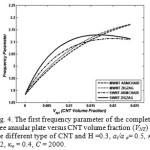 |
Figure 4: The first frequency parameter of the completely free annular plate versus CNT volume fraction (VNT) for the different type of CNT and H =0.3, ai/a o= 0.5, κo = 0.2, κw = 0.4, C = 2000. Click here to View figure |
Figure 5 depicts the effect of CNT diameter on the first frequency parameter of the completely free annular plate. In Fig. 5(a) the MWNT diameter value was varied from 10 nm to 50 nm, while for Fig. 5(b) the SWNT diameter value was varied from 0.8nm to 1.1nm. As can be clearly seen, increasing of either MWNT and SWNT values had a decreasing effect on the first frequency parameter, but, in comparison, the MWNT had a stronger influence on the frequency changes that for the SWNT which were nearly increasing diameters of independent of diameter changes.
![Fig. 5. The first frequency parameter of the completely free composite plate versus CNT volume fraction (VNT) for the different value of CNT diameter when H =0.3, κo = 0.2, C = 2000, ai/a o= 0.5. (a) MWNT κw = 0.4, ENT/M = 321.5, α = -11.83 (b) SWNT κw = 0.6, ENT/M = 354.43, α = -7.63 [31]](http://www.orientjchem.org/wp-content/uploads/2016/05/Vol32_No2_Thre_HAKI_Fig5-150x150.jpg) |
Figure 5: The first frequency parameter of the completely free composite plate versus CNT volume fraction (VNT) for the different value of CNT diameter when H =0.3, κo = 0.2, C = 2000, ai/a o= 0.5. (a) MWNT κw = 0.4, ENT/M = 321.5, α = -11.83 (b) SWNT κw = 0.6, ENT/M = 354.43, α = -7.63 [31] Click here to View figure |
The influence of the CNT shape factor parameter (c) on the first frequency parameters of the completely free annular plate for the different values of c from 200 to 20,000 is shown in Fig. 6. An increase in parameter c had resulted in an increase of the frequency parameter, especially in the middle of the domain where VNT was 5% for both the MWNT and SWNT cases.
Figures 7 a and b show the first frequency parameter of the completely free annular plate versus CNT volume fraction (VNT) for ρNT/M changes from 0.25 to 2 for the two cases, MWNT and SWNT, respectively. As they show, an increse in parameter ρNT/M had a decreasing effect on the frequency parameter for both MWNT and SWNT cases, but the MWNT samples were more affected by ρNT/M changes, increasing up to 20, than SWNT where it grew up to 16 for a maximum of ρNT/M equaled to 2, especially at the middle of the figures where VNT equals 5% for both MWNT and SWNT cases.
![Fig. 6. The first frequency parameter of the completely free annular plate versus CNT volume fraction (VNT) for the different value of CNT shape factor when. H =0.3, κo = 0.2, κw = 0.6, ai/a o= 0.5. (a) MWNT ENT/M = 321.5, (b) SWNT ENT/M = 354.43 [31]](http://www.orientjchem.org/wp-content/uploads/2016/05/Vol32_No2_Thre_HAKI_Fig6-150x150.jpg) |
Figure 6: The first frequency parameter of the completely free annular plate versus CNT volume fraction (VNT) for the different value of CNT shape factor when. H =0.3, κo = 0.2, κw = 0.6, ai/a o= 0.5. (a) MWNT ENT/M = 321.5, (b) SWNT ENT/M = 354.43 [31] Click here to View figure |
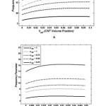 |
Figure 7: The first frequency parameters of the annular plate with free outer edge and clamped inner edge (F-C) versus CNT volume fraction (VNT) for the different value of when H =0.3, κo = 0.2, κw = 0.6, ai/a o= 0.5. (a) MWNT ENT/M = 321.5, (b) SWNT ENT/M = 354.43. Click here to View figure |
Conclusions
Based on the 3-D elasticity theory, a comprehensive study of the three-dimensional vibration analysis of carbon nanotube (CNT) reinforced composites annular plates with different combinations of free, simply-supported, and clamped boundary conditions at the inner and outer edges was investigated. The Chebyshev–Ritz method was applied to derive the eigenvalue. Due to the cylindrical nature of the annular plate geometry, the formulation was carried out in cylindrical polar coordinates.
In order to obtain precise results, a new form of the rule of mixtures, including an exponential shape function, length efficiency parameter κl, orientation efficiency factor κo, and waviness parameter κw was applied to have a proper prediction of the mechanical properties of CNT reinforced composites [31].
The validity and the range of applicability of the results was obtained based on other well-known theories (e.g., Halpin-Tsai, etc.) were studied by comparing results obtained using them with those obtained by our modified rule of mixtures. Moreover, the influence of the CNT type, structures, diameter, shape factor, density and volume fraction on the frequency parameter of the plate was also studied. Finally, we suggest the results presented in this paper can serve as benchmark results for researchers to validate their numerical methods and also for engineers to use such plates in their structures in the future.
Reference
- Allaoui, A.; Bai, S.; Cheng, H.M.; Bai, J.B. Compos. Sci. Technol. 2002, 62, 1993-1998
CrossRef - Azizian, J.; Hekmati, M.; Dadras, O. G. Orient. J. Chem. 2014, 30(2), 667-673
CrossRef - Baniasadi, L.; Omidi, M.; Amoabediny, G.; Yazdian, F.; Attar, H.; Heydarzadeh, A.; Zarami, A.S.H.; Sheikhha, M.H. Enzyme Microb. Technol. 2014, 63, 7-12
CrossRef - Ardjmand, M.; Omidi, M.; Choolaei, M. Orient J Chem., 2015, 31(4), 2291-2301
- Omidi, M.; Malakoutian, M.A.; Choolaei, M.; Oroojalian, F.; Haghiralsadat, F.; Yazdian, F. Chin. Phys. Lett. 2013, 30(6), 068701.
CrossRef - Omidi, M.; Amoabediny, G.; Yazdian, F.; Habibi-Rezaei, M. Chin. Phys. Lett. 2015, 32(1), 018701.
CrossRef - Soleymani, R.; Torkashvand, F.; Farsi-Madan, S.; Bayat, M. Orient J Chem., 2012, 28(2), 733-740
- Rokni, H.; Milani, A.S.; Seethaler, R.J.; Omidi, M. Int. J. Compos. Mater. 2013, 3(A), 45-57.
- Andrews R, Weisenberger MC. Curr Opin Solid St Mat Sci 2004, 8, 31
CrossRef - Ci L, Bai JB. Compos Sci Technol 2006, 66, 599
CrossRef - Yeh MK, Hsieh TH, Tai NH. Sci Eng A 2008, 483, 289
CrossRef - J. So, A.W. Leissa, J Sound Vibrat 1998, 209, 15
CrossRef - K.M. Liew, B. Yang, Int J Solids Struct 2000, 37, 7689
CrossRef - Taher, H.R.D.; Omidi, M.; Zadpoor, A.A.; Nikooyan, A.A. J. Sound. Vib. 2006, 296(4), 1084-1092
CrossRef - K.M. Liew, B. Yang, Int J Solids Struct 2000, 37, 7689
CrossRef - D. Zhou, F.T.K. Au, Y.K. Cheung, S.H. Lo, Int J Solids Struct 2003, 40, 3089
CrossRef - Hashemi, S.H.; Taher, H.R.D.; Omidi, M. J. Sound. Vib. 2008, 311(3), 1114-1140
CrossRef - Hashemi, S.H.; Omidi, M.; Taher, H.R.D. Eur. J. Mech. A Solids 2009, 28(2), 289-304
CrossRef - W. Lessia, NASA SP 160, Vibration of Plates, 1969
- Omidi, M.; Alaie, S.; Rousta, A. Meccanica 2012, 47, 817-833
CrossRef - Hedayati, H., and B. Sobhani Aragh. Appl Math Comput 2012, 218, 8715
CrossRef - Zhu, Ping, Z. X. Lei, and K. M. Liew. Compos Struct 2012, 94, 1450
CrossRef - Pouresmaeeli, S., E. Ghavanloo, and S. A. Fazelzadeh. Compos Struct 2013, 96, 405
CrossRef - Valavala PK, Odegard GM. Rev Adv Mat Sci 2005, 9, 34
- Odegard GM, Gates TS, Wise KE, Park C, Siochi EJ. Compos Sci Tech 2003, 63, 1671
CrossRef - Seidal GD, Lagoudas DC. Mech Mat 2006, 38, 884
CrossRef - Anumandla V, Gibson RF. Compos part A 2006, 37, 2178
CrossRef - Shao LH, Luo RY, Bai SL, Wang J. Compos Struct 2009, 87, 274
CrossRef - Kanagaraj S, Varanda RF, Zhil’tsova VT, Oliveira ASM, Simoes OAJ. Compos Sci Technol 2007, 67, 3071
CrossRef - Bokobza L. Polym 2007, 45, 4907
CrossRef - Omidi, M.; DT, H.R.; Milani, A.S.; Seethaler, R.J.; Arasteh, R. Carbon 2010, 48(11), 3218-3228
CrossRef - Mori T., Tanaka K. Acta Metal 1973, 21, 571
CrossRef - Cox HL. Br J Appl Phys 1952, 3, 72
CrossRef - Li CY, Chou TW. Int J Solids Struct 2003, 40, 2487
CrossRef - Hernandez E, Goze C, Bernier P, Rubio A. Phys Rev Lett 1998, 80, 4502
CrossRef - Lu JP. Phys Rev Lett 1997, 79, 1297
CrossRef - Krishnan A, Dujardin E, Ebbesen TW, Yianilos PN, Treacy MMJ. Phys Rev B 1998, 58, 14013
CrossRef - Erik T. Thostenson, Chunyu Li, Tsu-Wei Chou. Compos Sci Tech 2005, 654, 91
- Thostenson ET, Chou TW. J Phys D: Appl Phys 2003, 36, 573
CrossRef - Yeh MK, Tai NH, Liu JH. Carbon 2006, 44, 1
CrossRef

This work is licensed under a Creative Commons Attribution 4.0 International License.
![]()
A New Edition of Web of Science
Journal Impact Factor
2022: 0.5
Five Year: 0.8
Journal is Indexed in

Cabells Whitelist
![]()


