Na+ Ion Conducting Nano-Composite Solid Polymer Electrolyte – Application to Electrochemical Cell
K Manjula1* and V John Reddy2
1Department of Basic Science and Humanities, Vıgnan's Instıtute Of Management And Technology For Women, Hyderabad, Telangana, India.
2Department of Humanities and Sciences, Nalla Narasimha Reddy Education Society's Group of Institutions, Hyderabad, Telangana, India.
Corresponding Author E-mail: manju.navee@gmail.com
DOI : http://dx.doi.org/10.13005/ojc/380515
Article Received on : 19 Sep 2022
Article Accepted on : 20 Oct 2022
Article Published : 20 Oct 2022
Reviewed by: Dr. Manoranjan Behera
Second Review by: Dr. Pirim Setiarso y
Final Approval by: Dr. B.K. Sharma
Various concentrations of Multi Walled Carbon Nanotubes (MCNT) fillers dispersed PVDF- HFP: NaClO4 nanocomposite polymer electrolytes (NPE) were prepared by solution casting technique. The dispersion of MCNT nano fillers raised the accessibility of more ions for attaining the highest conductivity. Electrical conductivity, Ohmic resistance (RΩ), Polarisation resistanace (Rp), and Warburg impedance (W) were studied using electrochemical impedance spectroscopy (EIS), which revealed ion transport mechanics in the polymer electrolytes. The best ionic conductivity is found to be 8.46 × 10⁻³ Scm-1 for the 7 wt.% dispersed MCNT Nanocomposite Solid Polymer electrolyte among all polymer electrolyte samples. Electrochemical cell was made by PVDF-HFP:NaClO4 : MCNT polymer electrolyte and exhibited 1.95 V open circuit voltage and 2.5 mA short circuit current, respectively.
KEYWORDS:Analysis of the electrochemical cell; discharge rating; Electrochemical cell; impedance spectroscopy of PVDF-HFP and CNT
Download this article as:| Copy the following to cite this article: Manjula K, Reddy V. J. Na+ Ion Conducting Nano-Composite Solid Polymer Electrolyte – Application to Electrochemical Cell. Orient J Chem 2022;38(5). |
| Copy the following to cite this URL: Manjula K, Reddy V. J. Na+ Ion Conducting Nano-Composite Solid Polymer Electrolyte – Application to Electrochemical Cell. Orient J Chem 2022;38(5). Available from: https://bit.ly/3TibQVw |
Introduction
A significant amount of energy can currently be produced by electrochemical systems, which is the focus of electrochemists. A battery with a significant amount of energy storage capacity is one of them. These batteries have revolutionised the future usage of several technological applications. 1 Sodium is one of the elements being investigated as a replacement of lithium since it is easier to handle than lithium. It is an element that may be used efficiently in the manufacturing of solid polymer electrolyte (SPE) materials. 2 The increasing need for portable, flexible, and wearable electronic devices such as roll-up displays and electrochromic windows requires the usage of power sources such as batteries, solar cells, and supercapacitors with flexible PE. The PVDF-HFP acts as gelling agent and polymer electrolyte for hoping of ions in polymer structure. This polymer is highly suited for high harvesting applications because of Piezoelectric breakdown voltage and it also exhibits superior mechanical stability. 2 By incorporation of right amount of Na or Li salts in PVDF-HFP turns into effective ionic nature. The solid polymer electrolyte may be doped with the appropriate nanofillers to boost ionic conductivity. 3 The polymer PVDF-HFP is a semi-crystalline substance with a high dielectric constant. 4. The C-F group in PVDF-HFP coordinates with Na or Li ions which increases salt dissociation and it lead to generate high porosity in PVDF-HFP poymer electrolyte.5 The semi-crystalline character of PVDF-HFP may be attributed to the fact that PVDF is crystallised while HFP has an amorphous nature.6 The amourphous nature support good ionic conductivity of polymer electrolyte, semicrystallinity of polymer result high mechanical and temperature stability of polymer. Nanofiller is an excellent choice for use in nanoelectronic devices because to it provides high dielectric strength, outstanding chemical stability, and resistance to corrosion.7 These qualities make a perfect choice for preparation of polymer electrolyte for advance application. In the present investigation MCNT nanofiller is considered to be one of the most promising nanomaterial and doped in PVDF-HFP:NaClO4 polymer electrolytes. The conductivity of polymer electrolyte was studied by impedance spectroscopy and discharge characteristics of of fabricated Na/[PVDF-HFP: NaClO4: MCNT]/ (I2+MCNT(Nano)) electrochemical cell (EC) was studied.
Experimental
The materials PVDF-HFP with a molecular weight of less than 400,000, NaClO4 with a molecular weight of less than 331.3, and Nano powder MCNT with a particle size of less than 50,000 were procured from Sigma Aldrich. The well known solution casting process was used to produce nanocomposite polymer electrolytes. The PVDF-HFP, NaClO4 and MCNT were dissolved in the THF solvent for 24 hours, the mixture was then exposed to vigorous stirring at a 350C. After standardizing the mixture, it was poured on Petri dishes and allowed to evaporate to obtain the film. The polymer electrolyte electrochemical impedance evaluation was carried out using stainless steel electrodes and an AUTO LAB TYPE II potentiostat/galvanostat computer- controlled controlled EIS at 303K in the frequency range of 10 Hz to 1 MHz. In order to create the cathode, tetrahydrofuran (THF) is used to dissolved 100 mg of PVDF-HFP and 900 mg of MCNT nanotubes, and the mixture is agitated for twenty-four hours to generate a low-viscosity slurry. To increase the mobility of ions, 100 millilitres of iodine were added to the slurry. The low- viscosity slurry was then stirred for 5 hours to obtain the most compatible for preparing a film that was 1 centimetre and 0.5 millimetres thick. The film produced is being used as the cathode in an Electrochemical Cell. Using a PVDF-HFP: NaClO4: nano MCNT nanocomposite polymer electrolyte membrane as a separator between the Na anode and cathode in an EC. As a result, a conductible cell is produced. At room temperature, the 0.1 C and 0.2 C EC discharge rates were examined at room temperature.
Table 1: Different nanocomposite solid polymer electrolytes in a range of composition ratios have been designated as the samples.
|
Sample designation |
Composition ratios of nanocomposite solid polymer electrolytes (PVDF-HFP: NaClO4: MCNT) |
||
|
PVDF-HFP polymer |
NaClO4 salt |
nano filler MCNT |
|
|
MCNT5 |
1000mg |
400mg |
15mg |
|
MCNT7 |
1000mg |
400mg |
17mg |
|
MCNT9 |
1000mg |
400mg |
19mg |
Impedance Spectroscopy
Results and Discussion
The most effective method for examining polymer electrolyte conductivity and transport mechanism is via electrochemical impedance spectroscopy (EIS). The impedance spectra of the samples MCNT05, MCNT07, and MCNT09 are shown in Figure 1. The First zone of EIS pectra high frequency region Ohmic resistance (RΩ), meddile frequency region which is known as charge transfer resistance (Rct), and the low frequency region is known as Warburg impedance (W). The high frequency intersecting point of semicircle on real axis of Z1 represent ohmic resistance (RΩ), The diameter of semi circle represent the polarization resistance or charge transfer resistance of PE, And the intersecting point at real axis Z1 at lower frequency of impedance spectroscopy represence bulk resistance (Rb).8,9 At very low frequency region where impedance occurs for dispersion ions in PE represented by Warburg impedance (W).

The ohmic resistance, which is shown by “RΩ,” is not only the total of the solution and film resistances. But itis also changes depending on the potential because conductivity changes with potential. The symbol”RΩ,” represents the overall resistivity of the bulk material, which stands for “ohmic resistance” and is produced by the electrolyte, electrode, and counter electrode interactions. The RΩis computed without an inductor and with the effects of the capacitor taken into account.
It is entirely dependent on the cyclic process of contact between electrodes and electrolytes broug ht on by oxidation and reduction.
 |
Figure 1: depicts the impedance spectra of a) MCNT05 b)MCNT07 d)MCNT09. Click here to view figure |
 |
Figure 2: Schematic diagram of ohmic resistance, charge transfer resistance and Warburg impedance with pseudo capacitance. |
 |
Figure 3: Variation of ohmic resistance of MCNT05, MCNT07, MCNT09. |
The ohmic resistance quickly decreases as the number of nanofillers rises, as seen in Figure 3. As the concentration of MCNT nanoparticle dispersion rises, the electrode-electrolyte, electrolyte- electrode, and electrolyte ohmic resistance decrease. Owing to an advantageous electron-ion interaction at the electrode-electrolyte and electrolyte-electrode interfaces without charge buildup.
The dispersed MCNTnanofillers at the polymer electrolyte Interfaces establish a link for the exchange of ions and electrons between the electrode and the electrolyte, as well as between the electrolyte and the electrode.At the electrode-electrolyte and electrolyte-electrode interfaces as well as the porous interconnecting network, there is an accumulation of distributed nanofillers, causes the ohmic resistance to rise with increasing concentrations of MCNT nanoparticles. The diameter of the semicircle in the electrochemical impedance spectroscopy may be used to calculate the charge transfer resistance (Rct). Figure 4 depicts this notion, also known as polarization resistance.Ionic resistance falls under the charge transfer resistance umbrella. Polarization at each layer results in resistance to ionic electrolyte mobility, electrical resistance between electrode-polymer and polymer-current collector, as well as in the network of interconnected porous polymer membranes.
The resistance is the result, it becomes to the ion mement in the polymer matrics. Smaller charge transfer resistance is shown by the semicircle’s short diameter in the impedance spectra. The reason can be expected from R/C ratio, which reveals about combination of electrical and ionic resitance. Electrode/electrolyte, electrolyte, and electrolyte/ counter electrode is the cause of Charge transfer resitance, this layers appears as capacitive elements as it posses polarization at every layer interface. The polarization resitance decreases as the concentration nan filler dispersion increases from sample MCNT05 to MCNT09. The least amount of polarization can be recorded to sample MCNT09. The Optimum concentration of MCNT nano filler dispersion can establish a contact between electrode and electrolyte interface. The contact between the electrolyte layer and electrode-electgrolyte may leads to reduction of polarization resistance, which is very essential for ion hoping. Further raise of concentration MCNT nano fillers in the sample MCNT12 leads to increases of polarization resistance. The more dispersed concentration of MCNT nano fillers in the sample MCNT12 may act as polarization center ion hoping and it may leads to raise in polarization. Among MCNT05, MCNT09 and MCNT12, the optimum lest polarization is shown for the Sample MCNT09 in Fig.05.
 |
Figure 4: Change of polarization resistance of MCNT05, MCNT07, MCNT09. |
The Warburg dispersive impedance measures the amount of ion mobility in a polymer electrolyte. The semicircle deviates owing to non-ideal capacitance generated by the properties of ions and electrons during diffusion in electrodes and polymer samples. Warburg impedance (W) in series with polarisation resistance also demonstrates this. Warburg impedance (W) may also occur as a consequence of diffuse mass transfer, which is especially visible at lower frequencies and is depicted in Pooja Vadhva et al. Due to the porous nature, charge transfer resistance and Warburg impedance are reduced, and the region of effective interface between nanofillers and polymer electrolytes is increased. which may support a rise in ionic conductivity. More number of porous non inter connecting net work may leads to high Warburg impedance, as the porous network may leads to pseudo-capacitance,10 which will increase the diffusion length.11 The increased concentration of fillers from MCNT05 to MCNT09 results in a lower Warburg impedance. Good ionic conductivity may be established via a well-connected high porous network.
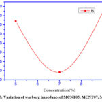 |
Figure 5: Variation of Warburg impedance of MCNT05, MCNT07, MCNT09. |
 |
Figure 6: Variation of conductivity of MCNT05, MCNT07, MCNT09. |
Higher concentration of MCNT nanofiller in MCNT12 sample will distruct the inter connectivity of porosity, It may result bad ionic Conductivity by producing pseudo-capacitance which may result of raise in warburg impedance.The variation of Warburg impedance can clearly can be seen Fig.6.
The ionic conductivity variation can be seen the Fig. 7 And highest conductivity was recorded for the Sample MCNT09. Finally MCNT09 is showing low ohmic Resistance (R ), polarization resistance (Rp), or charge transfer resistance (Rct) and Warburg impedance (W) resulting a prominent ionic conductivity σ = 8.46 × 10⁻³ Scm-1.
Electrochemical Discharge Rating
 |
Figure 7: Discharge characteristics of an electrochemical cell with different C-ratings: a) 0.1C rating discharge; b) 0.2 C rating discharge cover. |
A nanocomposite PE consisting of [PVDF-HFP: Na(ClO4)2: nano MCNT] (1000:400:12) was put between the anode and the cathode in the configuration Na/ (1000:400:17) [PVDF-HFP: NaClO4: MCNT]/ (I2+MCNT(Nano)) to build the EC. Combining the right mix of MCNT and iodine will improve charge collection efficiency since the MCNT cathode boosts the composite cathodic nature, (I2+MCNT) is used as cathode.12 The discharge performance of [PVDF-HFP: NaClO4: MCNT(nano)] polymer electrolyte employed between Na anode and (I2+MCNT) cathode was studied at the discharge rate 0.1C and 0.2C at room temperature is depicted in Fig.7. The discharge current was 260 milliamperes, Where as the open circuit voltage was notice as 1.9554 volts. 0.2 C rate of discharging of EC represent a good stability till 120 mA and for 0.2 C rating discharge represent130 mA. A good electrochemical Voltage stability can be seen thought the EC discharge.
Conclusions
The solution cast method is used to dispers various MCNT (nano fillers) into PVDF-HFP: NaClO4 to prepared MCNT05, MCNT09 and MCNT12 polymer electrolytes. The polymer electrolyte membranes electrical studies such as Polarization resistance, Ohmic Resistance and Warburg impedance was done by Electrical impedance spectroscopy. Lowest Polarization resistance and Warburg impedance were noticed to MCNT12 Polymer electrolyte sample with highest conductivity 6.62 x 10⁻² S Cm-1. And good electro chemical stability was represent by MCNT12 polymer electrolyte sample with 0.1C and 0.2C rating of discharge of EC.
Acknowledgement
The authors thank HoD(H&S), Principal, and Management of Vıgnan’s Instıtute Of Management And Technology For Women and NNRG for their encouragement and carrying out this research work.
Conflict of Interest
Authors declares no conflict of interest.
Funding Sources
There is no funding Sources
References
- Zheng Jin.; Hu Yan-Yan, ACS Appl. Mater. Interface., 2018, 10, 4, 4113–4120.
CrossRef - Karabelli D.; Singh S.; Kiemel S.; Koller J, Konarov A.; Stubhan F.; Miehe R.; Weeber M.; Bakenov Z and Birke KP, Front. Energy Res., 2020, 8:605129
CrossRef - Shun Ai.; Sayantan Mazumdar.; HaifengLi.; Yongge Cao and Tao Li, Journal of Electroanalytical Chemistry., 2021,895,115464.
CrossRef - Gohel.; Khushbu.;D. K. Kanchan, and C. Maheshwaran, AIP Conference Proceedings., 2018, 1, 1942.
- Yesappa L, RSC advances., 2018,8.28, 15297-15309.
CrossRef - Abbrent S., Polymer., 2001, 42.4, 1407-1416.
CrossRef - Li M.; Jin ZX, and Zhang W, Sci Rep.,2019, 9, 10438.
CrossRef - Nofal MM.; Aziz SB.; Ghareeb HO.; Hadi JM.; Dannoun EMA and Al-Saeedi SI, Materials., 2022, 15(6),2143.
CrossRef - Ganta K.K..; Jeedi V., and Katrapally, J. Inorg Organo met. Polym., 2021, 31, 3430– 3440.
CrossRef - Juan Zhao.; QiL.i; TongxinShang.; FeifeiWang.; JunZhang.; ChuannanGeng.; ZhitanWu.; YaqianDeng.; WeichaoZhang.; YingTao, and Quan-Hong Yang, Nano Energy., 2021, 86, 106091.
CrossRef - Inoue Gen, and Kawase Motoaki, Journal of Power Sources., 2016,1-10,327.
CrossRef - Stolyarov R, IOP Conference Series: Materials Science and Engineering. 2019, 1, 693.
CrossRef

This work is licensed under a Creative Commons Attribution 4.0 International License.
About The Author
![]()
A New Edition of Web of Science
Journal Impact Factor
2022: 0.5
Five Year: 0.8
Journal is Indexed in

Cabells Whitelist
![]()


