Structural and Electrical Conductivity Studies of PVDF-HFP Film Filled with Tio2 and Nacl for Polymer Semiconductors
N. Ramaiah1* , V. Raja2 and Ch. Ramu1
1Department of Physics, Vikrama Simhapuri University Postgraduate Center, Kavali - 524201, A.P, India.
2Department of Physics, NBKR Science and Arts College, Vidyanagar - 524413, A.P, India.
Corresponding Author E-mail: iah.rama@gmail.com
DOI : http://dx.doi.org/10.13005/ojc/370513
Article Received on : 25-Aug-2021
Article Accepted on :
Article Published : 15 Sep 2021
Reviewed by: Dr. Bhabani Shankar Panda
Second Review by: Dr. Gunasekaran S.G
Final Approval by: Dr. Tanay Pramanik
As prospective electrolyte membranes are fabricated using a conducting copolymer of poly (vinylidene difluoride-co-hexaf luoropropy lene) (PVDF-HFP) by a solution casting method. The prepared membranes were filled with an electrical conductor (NaCl) and semiconductor (TiO2) nanopowder in this method. The assimilated membranes were analytically characterized by scanning electron microscope (SEM) for surface morphology and X-ray diffraction (XRD) for crystalline nature of the TiO2 nanopowder present in the prepared membrane. The FTIR confirms the structural analysis of the copolymer and the NaCl and TiO2 incorporation nature into the PVDF-HFP membrane. Electrochemical stability of the fabricated membrane of PVDF-HFP was performed using thermo-gravimetric analysis (TGA). The cyclic voltammetric analysis conducted the charge and discharge tests of the filled and unfilled membrane. The addition of nano TiO2 particles and NaCl to the copolymer membrane was found to reduce the PVDF-HFP membrane's porousness and improve the ion conductivity and electrolyte/electrode interfacial stability of the filled membrane.
KEYWORDS:Cyclic Voltammeter; Ionic conductivity; Polymer membrane; PVDF-HFP; TiO2 nano powder
Download this article as:| Copy the following to cite this article: Ramaiah N, Raja V, Ramu C. Structural and Electrical Conductivity Studies of PVDF-HFP Film Filled with Tio2 and Nacl for Polymer Semiconductors. Orient J Chem 2021;37(5). |
| Copy the following to cite this URL: Ramaiah N, Raja V, Ramu C. Structural and Electrical Conductivity Studies of PVDF-HFP Film Filled with Tio2 and Nacl for Polymer Semiconductors. Orient J Chem 2021;37(5). Available from: https://bit.ly/3lsjZqJ |
Introduction
Energy-source devices, for example, power modules can be ready as a choice to work on the nursery impact from fossil fuel byproducts in the absolute world1. Polymer layers as electrolytes have been broadly examined because of the possibility of their business use in an assortment of electrochemical techniques like electrochemical cells, battery-powered batteries, and sensors2. Proton trade film power device is one of the energy sources which apply the electrochemical rule to produce high-proficient power (40–60%), work at low temperature (50– 100 oC), and be perfect and eco-friendly method and materials3. Associated with other types of electrolytes, the polymer solid membrane electrolytes have many advantages of existence mechanically elastic, low in molecular weight, easy to handle. Recently, the vast and majority of the researchers in the world have been focused on the improvement of non-noble metal energies and novel polymer electrolyte films for battery applications. All the while, first-rule estimations and sub-atomic elements simulations have also been broadly utilized to research the catalytic device, just as the transportation conduct, which broadens our comprehension of the fundamental synthetic and actual cycles and essentially speeds up the investigation of novel materials.
For utilization in high energy device batteries, there are three types of polymer solid electrolytes according to their structural designs: namely dry polymer solid electrolyte membranes, gel polymer solid electrolyte, porous structured polymer solid electrolytes and doped thin-film polymer solid electrolytes4. For the preparation of various types of these polymer solid electrolytes, a variety of chemical structured polymers were used such as extending a form of polyethene oxide5, poly (vinylidene fluoride)6, poly (methyl methacrylate)7and polyacrylonitrile8. The incorporated materials increase the ionic conductivity of the prepared polymer electrolyte by fading the crystallinity of the polymer and furthermore introduce Lewis acid-base interfaces between the polar surface gatherings of the inorganic filler and the electrolyte ionic species9, 10. The membrane properties, for example, porosity and consistency of pore dispersion are subject to its fabrication technique. Various preparation methods like the solution casting method11, plasticizer extraction12, phase reversal13 and electrospinning14 have been accounted for the membrane were used. Solid-phase polymer electrolytes can defeat the safety problem of sodium ion (Na+) particle in batteries because Na+ ions are not containing combustible liquid chemicals in their framings.
Many studies have been conducted to develop novel cathode materials that will provide high power, large capacity, high rate capability, and security for future generations of Na-ion batteries. It is feasible to increase the overall battery energy density and thickness by combining such an electrode with proper structural design and suitable material to eliminate the requirement for a separator membrane, binders, conductive additives, or current collectors.Then again, gel polymer electrolytes were prepared by gel nature liquid electrolytes with polymer complex has many advantages over both liquid electrolyte and glass electrolytes15. Permeable structured gel polymer electrolytes have a relationship with electrolyte and separator as the consolidated membrane. As contrasted and liquid electrolytes, polymer solid electrolytes can productively prevent electrolyte outflow and prevents the firing hazard, which primes to the more safety of business batteries16. Meanwhile, porous structured polymer solid electrolytes can give high ionic conductivity, great processability, a wide scope of electrochemical working space, and good thermal stability17-19.
However, high porous structured polymer solid membranes can induce internal short circuits, and causing the failure of the batteries. In order to rectify the failure of the general batteries, so many methods have been introduced to reduce the pore size and the inorganic ions and nano-sized particles were used as fillers to increase the ionic conductivity of the electrolytic solid polymer membrane. In the present study of the incorporation of TiO2 nanoparticles and NaCl as inorganic ions were used as filler to reduce the porous size of the prepared solid poly (vinylidene difluoride-co-hexafluoropropylene) membrane and to increase the ionic conductivity of the electrolytic solid polymer membrane.
Experimental
Materials
The reagents used in this study were purely analytical grade with 99% purity and no further purification. Copolymer of Polyvinylidene fluoride-co-hexafluoropropylene (PVDF-HFP), TiO2 nano powder as filler and sodium chloride (NaCl, ≥99.5%) to reduce the porousness of the solid polymer membrane, 1-Ethyl-3-methylimidazolium dicyanamide (EMIMDCA) as electrolytic solution and all are obtained from sigma Aldrich lab, Mumbai. Double distilled water was used throughout the experiment for the fabrication of solid membrane and cleaning of the filled membrane.
Preparation of porous structured PVDF-HFP solid membrane
7.2 gm of the copolymer of PVDF-HFP was dispersed in 250 mL of electrolytic solution of EMIMDCA and permitted to stir for 24 hours on a magnetic stirrer at laboratory conditions to continue to make the homogeneous polymer solution. 25 mL of the above electrolytic homogeneous polymer solution was divided into four different volumetric beakers by measuring 5 mL of aqueous nano TiO2 dispersedsolution. The combination of the solution was permitted to mix for the total dispersion of nano TiO2 powder particles into the polymer solution for 2 hours at constant stirring. Further, the combination of the homogeneous arrangement was moved into glass Petri plates and permitted to dry at laboratory conditions lastly happens the formation of thin sized strong solid polymer films. The obtained films were permitted to dip in various concentrations (0.01N, 0.02N, 0.03N and 0.04N) of the standard NaCl aqueous solutions for 6 hours. After that, the films were removed from the NaCl solution and dried for 2 hours under laboratory conditions. The completed strong electrolytic films were rinsed twice with distilled water and dried for four hours at 50 °C in the oven. The polymer solid membranes that had been manufactured were saved for further analytical characterization and battery applications.
Analytical characterization of filled PVDF-HFP membranes
The inorganic material filled solid membranes were characterized with different analytical techniques for identification and confirmation of the formation of inorganic materials filled PVDF-HFP membranes. The functional groups of the copolymer and filled membrane were analysed by SHIMADZU Fourier-transform infrared spectroscopy (FTIR). The presence and crystalline nature of TiO2 nanopowder and NaCl in the pores of the PVDF-HFP solid membrane were examined by Bruker-Germany, model D8 X-ray diffractometer (XRD). The external morphology and porous nature of the polymer membrane were confirmed by the JOEL model JSM- 6390 LV SEM analyzer. The % of each inorganic element in the fabricated solid polymer membrane was performed by an energy-dispersive X-ray diffractometer (EDX). Thermal and electrochemical stability of the prepared solid membrane was performed using a Thermogravimetric analyzer (TGA). Moreover, the Electrochemical performance of the prepared PVDF-HFP film was gotten utilizing a Metrohm Auto lab with a frequency response examination (FRA) module.
Battery assembly and testing the performance of the electrolytic membrane
For the battery assembly on aluminium foil, the PVDF-HFP strong electrolytic film was used as an anode. TiO2 nanopowder and NaCl are commonly used as current collectors because they exhibit the mind-boggling predicted interaction with electrolytes20. The LiCoO2 is most likely used as a cathode, with mass deposition of roughly 12 mg/cm2 guaranteed by the MTI Corporation21. On both the anode and cathode, the electrical association was applied to employ a copper strip. The addition of electrolyte (NaCl) to the TiO2 filled PVDF-HFP strong solid film reduced the interfacial resistance in the battery.Furthermore, the battery was encased in the machine by a thermal-adhesive plastic covering sheet. The battery was attempted to be tested by disclosing copper strips after the superfluous parts of the sheets were cut off. Using cyclic voltammetry (1.5V to 2.8V) with a 0.05mV/second output range, the battery’s functional presentation was determined. The Arbin battery test device was also calibrated for cycle execution at a constant thickness (35mA/mg) and a voltage range of 1.6V – 2.7V.
 |
Scheme 1: Schematic representation of fabrication ofPVDF-HFP (NaCl) membrane. |
Results and Discussion
Fourier-transform infrared spectroscopy (FTIR) analysis
The structural composition of the solid PVDF-HFP film and after incorporating with NaCl and TiO2 nanopowder was investigated using FTIR spectroscopy (Fig. 1). The resultant peaks at different wavelengths such as absorbance peaks at 2933 cm-1 and 1625 cm-1 represented the C-H stretching vibrations of the carbonyl functional group and at 1680 cm-1 represents the C=C peak respectively in both polymer solid membranes which were in Fig 1A and 1B22. In addition, the peaks at 1384 cm-1 and1193 cm-1 represented the phenolic C-O group on the aromatic ring of the copolymer present in both solid membranes. A small intense peak is appeared at 880 cm-1 and indicates the CF2 stretching peak in the structure and a peak at 835 cm-1 represents the CH2 rocking in the aromatic ring of the PVDF-HFP. The evidence of the inorganic fillers i.e., NaCl and TiO2 nanopowder present in the solid membrane is not involved any chemical reaction in the membrane formation. Furthermore, a small change in chemical composition was observed and it is due to the excitation of the electrolytic components in the filled PVDF-HFP solid membrane in the electrolytic solution. A sharp and strong peak was observed at 842 cm-1 and indicates the chlorine in the membrane composition. After filling with NaCl and TiO2 nanopowder, the peaks were relocated to a longer and shorter frequency without affecting the frequency23.
 |
Figure 1: FTIR spectral studies of pure PVDF-HFP copolymer (A) and NaCl Electrolyte filled PVDF-HFP solid membrane (B). |
SEM analysis of NaCl electrolyte PVDF-HFP solid polymermembranes
The morphology and porousness of both plain electrolytic PVDF-HFP copolymer membrane and inorganic materials filled solid polymer membrane were analysed by the SEM analysis depicted in Fig. 2. The attained results specified that both solid membranes having a smooth surface and distributions of NaCl and TiO2 nanopowder into the porous structure PVDF-HFP solid polymer membrane. Fig. 2 (A, B & C) are the before filling of the NaCl and TiO2 and Fig. 2 (D, E & F) are the after filling of the NaCl and TiO2 nanopowder into the membrane. This result confirms the pores present in the solid membranes were filled with both TiO2 andthe electrolytic solution of NaCl.The filled materials increase the conducting property of the microstructure of the PVDF-HFP solid polymer membrane.
 |
Figure 2: Digital SEM images of PVDF-HFP membranes before filling with (A, B & C); after filling with NaCl and TiO2 (D, E & F) with different magnifications. |
Energy-dispersive x-ray (EDX) spectral analysis of filled PVDF-HFP solid membrane
The EDX of the filled PVDF-HFP solid membrane revealed that the presence of all elements in the prepared solid polymer membrane. Fig. 3 confirms the presence of Na, Ti & Cl in the composition of the solid membrane and their importance in the battery application. The increase in conductivity was seen by the incorporation of NaCl and TiO2 into the PVDF-HFP solid polymer film. The permeable size of the film assumes a critical part in the increase of conductivity by the filling of electrolytes of NaCl and TiO2 nanopowder. Previous reports state that high the porousness of the membrane material possesses low conductivity24, by filling these pores with suitable electrolytic materials minimize the porous nature and increases the conductivity of the prepared membranes25. Fig. 3 clearly confirms that the filling of both NaCl and TiO2 nanopowder into the pores of the PVDF-HFP solid membrane and specifies that PVDF-HFP solid polymer membrane show increasing of conductivity after filling with inorganic electrolytes.
 |
Figure 3: EDX spectra of TiO2 and NaCl filled PVDF-HFP solid polymer membrane. |
X-ray diffraction analysis
The incorporation of TiO2 and NaCl into the PVDF-HFP solid polymer film and the crystalline nature of the film were established through the XRD analysis. From Fig. 4, it was clearly assigned the crystalline peaks of the TiO2 and NaCl present in the PVDF-HFP solid electrolytic film. Fig. 4(A) not determined any peaks corresponding to the TiO2 nanopowder and addresses the PVDF-HFP solid film before the incorporation of electrolytes and Fig. 4(B) confirmed the crystalline nature of TiO2 nanopowder as a tetragonal structure26. The 2θ values, for example, at 25.7°, 38.5°, 49.5°, 53.2°, 54.3°, 55.2° and 63.14° of XRD data of TiO2 nanopowder were answerable for the miller operator records esteems (101), (112), (200), (105), (211) and (204) individually. Fig. 4A and 4B obviously demonstrated the crystalline design of the pre-arranged polymer solid film containing the TiO2 nanopowder in the permeable film. The PVDF-HFP solid polymer membrane was compared to the results before and after inclusion with NaCl and TiO2 inorganic materials, and no crystalline peaks were identified in the PVDF-HFP solid polymer film (Fig. 4A).
 |
Figure 4: XRD spectral analysis of pure PVDF-HFP solid membrane before filling (A), and (B) after filling with TiO2 nano powder and NaCl electrolytes. |
Thermo gravimetric analysis (TGA)
The thermal stability of the fabricated solid membrane of the PVDF-HFP solid membrane, NaCl and TiO2 nanopowder filled polymer films were investigated utilizing TGA examination. The TGA results were displayed in Fig. 5 and examined the weight reduction of the PVDF-HFP polymer film with NaCl and TiO2 powder-filled PVDF-HFP-TiO2 layer. The thermal stability of the all-solid polymer membranes was determined in between 0 °C to 600 °C temperature and the decrease of the slight gradual weight loss was observed when TiO2 nanopowder and NaCl electrolytic solution was filled into the PVDF-HFP solid membrane at high temperature such as 600 °C27. NaCl and TiO2 nanopowder filled solid membrane plays a foremost part in the membrane’s thermal stability and weight loss at operating conditions.
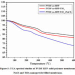 |
Figure 5: TGA spectral studies of PVDF-HFP solid polymer membrane, NaCl and TiO2 nanopowder filled membrane. |
Electrochemical performance of the solid polymer membrane
The take-up and leakage behaviour of the electrolytic solution (NaCl) in the PVDF-HFP solid polymer film was displayed in Fig. 6. The porous structure network of the PVDF-HFP film was thought to enable much faster penetration of TiO2 nanopowder and NaCl electrolytic solution into the film pores28, 29. Plain and PVDF-HFP solid polymer film showed a take-up electrolyte of 260 to 330 wt. % after 1 to 250 min of analyzed time individually. TiO2 nanopowder and NaCl electrolytic solution filled strong polymer film; take-up ability was improved because of the enhanced of an undefined stage. The filled strong film showed a take-up electrolyte of around 280 % to 350 % for 1 minute to 250 minutes.
 |
Figure 6: Uptake and leakage behavior of the PVDF-HFP solid membrane before filling and after filling with NaCl and TiO2 nanopowder. |
The leakage execution of the electrolytic NaCl solution is extremely critical for the cycling execution of Na+ particle batteries30. To inspect the leakage performance of the electrolytic NaCl solution, a spot was duplicated as same as working batteries by setting the filled PVDF-HFP solid film between two-channel papers. As displayed in Fig. 6, the deficiency of the NaCl expanded continuously until the analyzed time arrived at 2 hours 30 minutes. The films PVDF-HFP and inorganic electrolyte filled PVDF-HFP strong film held 78% and 86% of the underlying absorption ratio separately. Both the filled and unfilled strong films showed great take-up and spillage properties which were adequate for genuine Na+ particle battery applications. Be that as it may, the inorganic electrolytes filled PVDF-HFP strong layers showed a bigger number of takes-up and less spillage than unadulterated PVDF-HFP strong layers in light of their lower crystallinity and high permeability.The stable electrolyte filled PVDF-HFP solid polymer sheet also has a conductivity of 6 X 10⁻³S/cm.
The cycle presentation of the model cells was displayed in Fig. 7. The essential release limits of the two cells were analyzed somewhere in the range of 135 and 140 mAh g−1. The full cells with inorganic electrolytes filled the PVDF-HFP layer displayed stable release conduct and little volume misfortune under stable current stream conditions, which actually held a limit of 130 mAh g−1 after the presentation of 140 cycles. The further developed cycle execution of the model cells with inorganic electrolytes filled PVDF-HFP strong layer could be somewhat seen for the low spillage in the permeable construction of the cell film because of its penetrability31.
 |
Figure 7: Cycle performance of the PVDF-co-HFP membrane before filling and after filling with NaCl and TiO2 nano powder. |
Conclusion
In this current study, the authors have fabricated the NaCl and TiO2 filled PVDF-HFP solid polymer membrane using PVDF-co-HFP and EMIMDCA solvent. Primarily, the filled PVDF-HFP and pure electrolytic membranes were characterized by various analytical techniques. FTIR analysis confirmed the functional group interactions and involvement in the formation of porous structured solid membrane and incorporation of inorganic electrolytes into the pores of the membrane. The results of the SEM images confirm the porousness of the prepared PVDF-HFP membrane and inorganic electrolytes filled PVDF-HFP solidmembranes. The incorporation of the inorganic electrolytes (NaCl and TiO2) was confirmed by examination with EDX analysis and gives elements present in the PVDF-HFP solid polymermembrane. XRD analysis describes the structural and crystalline nature of the fabricated electrolyte filled membranes. The thermal stability of the plain membrane and NaCl and TiO2 nanopowder filled polymer solid membranes were analysed by TGA curves and retain good thermal stability at high temperatures. These filled and unfilled membranes have good results in the electrolyte uptake and leakage behaviour in battery applications. In addition, the completed results confirmed that the high conductivity was obtained with the 1.5 Ve 2.8 V reach and that no further pinnacles were visible in the results. The stable electrolyte filled PVDF-HFP solid polymer sheet also has a conductivity of 6 X 10⁻³ S/cm.
Conflict of interest
The authors declared that they have no conflict of interest
Acknowledgment
The authors wish to thanks to Dr Chandra Sekhar Espenti, Assistant Professor, Dept. of Chemistry, RGM College of Engineering & Technology, Nandyal, AP, India for helping in the construction of the manuscript.
References
- Gérardin, K.; Raël, S.; Bonnet, C.; Arora, D.; Lapicque, F. Fue. Cel. 2018, 18, 315-325.
CrossRef - Gebreyesus, M. A.; Purushotham, Y.; Kumar, J. S. Heli.2016, 2, e00134.
CrossRef - Qin, C.; Wang, J.; Yang, D.; Li, B.; Zhang, C. Cataly. 2016, 6, 197.
CrossRef - Tolganbek, N.; Mentbayeva, A.; Serik, N.; Batyrgali, N.; Naizakarayev, M.; Kanamura, K.; Bakenov, Z. J. Pow. Sour.2021, 493, 229686.
CrossRef - Ding, W. Q.; Lv, F.; Xu, N.; Wu, M. T.;Liu, J.; Gao, X. P. ACS Appl. Ener. Mat. 2021, 4, 4581-4601.
CrossRef - Choi, S. W.; Kim, J. R.; Ahn, Y. R.; Jo, S. M.; Cairns, E. J. Chem. Mat.2007, 19, 104-115.
CrossRef - Bohnke, O.; Frand, G.; Rezrazi, M.; Rousselot, C.; Truche, C. Sol. Stat. Ionic.1993, 66, 97-104.
CrossRef - Peramunage, D.; Pasquariello, D. M.; Abraham, K. M. J. Elec. chem. Soc.1995, 142, 1789.
CrossRef - Chung, S. H.; Wang, Y.; Persi, L.; Croce, F.; Greenbaum, S. G.; Scrosati, B.; Plichta, E. J. Pow. Sour. 2001, 97, 644-648.
CrossRef - Croce, F.; Appetecchi, G. B.; Persi, L.; Scrosati, B. Nat.1998, 394, 456-458.
CrossRef - Moore, R. B.; Martin, C. R. Analy. Chem.1986, 58, 2569-2570.
CrossRef - Long, L.; Wang, S.; Xiao, M.; Meng, Y. J. Mat. Chem. A. 2016, 4, 10038-10069.
CrossRef - Wijmans, J. G.; Smolders, C. A. Syn. Mem.: Sci. Eng. Appl. 1986, 39-56.
CrossRef - Ghavimi, M. A.; Negahdari, R.; Bani Shahabadi, A.; Sharifi, S.; Kazeminejad, E.; Shahi, S.; Maleki Dizaj, S. Eur. Chem. Com.2020, 2, 122-127.
- Arya, A.; Sharma, A. L. Ionic. 2017, 23, 497-540.
CrossRef - Yao, P.; Yu, H.; Ding, Z.; Liu, Y.; Lu, J.; Lavorgna, M.; Liu, X. Front. Chem.2019, 7, 522.
CrossRef - Wei, Z.; Ren, Y.; Wang, M.; He, J.; Huo, W.; Tang, H. Nanosc. Res. Let.2020, 15, 1-8.
CrossRef - Narayanagari, R.; Vukka, R.; Chekuri, R. J. Polym. Res. 2021, 28, 1-7.
CrossRef - Balaish, M.; Gonzalez-Rosillo, J. C.; Kim, K. J.; Zhu, Y.; Hood, Z. D.; Rupp, J. L. Nat. Ene. 2021, 6, 227-239.
CrossRef - Pender, J. P.; Jha, G.; Youn, D. H.; Ziegler, J. M.; Andoni, I.; Choi, E. J.; Mullins, C. B. ACS nano. 2020, 14, 1243-1295.
CrossRef - Idris, R.; Mohd, N. H. N.; Arjan, N. M. Ionic. 2007, 13, 227-230.
CrossRef - Bai, H.; Wang, X.; Zhou, Y.; Zhang, L. Prog. Nat.Sci. Mat. Inter. 2012, 22, 250-257.
CrossRef - Lee, S. Y.; Kang, D.; Jeong, S.; Do, H. T.; Kim, J. H. ACS omeg.2020, 5, 4233-4241.
CrossRef - Lu, W.; Yuan, Z.; Zhao, Y.; Zhang, H.; Zhang, H.; Li, X. Chem. Soc. Rev.2017, 46, 2199-2236.
CrossRef - Yamaguchi, T.; Miyata, F.; Nakao, S. I. J. Mem. Sci. 2003, 214, 283-292.
CrossRef - Khade, G. V.; Suwarnkar, M. B.; Gavade, N. L.; Garadkar, K. M. J. Mat. Sci. Mat. Elec.2016, 27, 6425-6432.
CrossRef - Vekariya, R. L., Dhar, A., Paul, P. K., & Roy, S. Ionic. 2018,24, 1-17.
CrossRef - Baranowska-Wójcik, E.; Szwajgier, D.; Oleszczuk, P.; Winiarska-Mieczan, A. Bio. Tra. Elem. Res.2020, 193, 118-129.
CrossRef - Benhabiles, O.; Galiano, F.; Marino, T.; Mahmoudi, H.; Lounici, H.; Figoli, A. Mol. 2019, 24, 724.
CrossRef - Eshetu, G. G.; Elia, G. A.; Armand, M.; Forsyth, M.; Komaba, S.; Rojo, T.; Passerini, S. Adv. Ene. Mat.2020, 10, 2000093.
CrossRef - Bui, V. T.; Nguyen, V. T.; Nguyen, N. A.; Umapathi, R.; Larina, L. L.; Kim, J. H.; Choi, H. S. Membr.2021, 11, 41.
CrossRef

This work is licensed under a Creative Commons Attribution 4.0 International License.
About The Author
![]()
A New Edition of Web of Science
Journal Impact Factor
2022: 0.5
Five Year: 0.8
Journal is Indexed in

Cabells Whitelist
![]()


