Influence of Pressure and Thermal Parameters on Stresses Analysis of Pressurized and Cracked Pipes
Abdullah K. Okab1, Khalid A. Mohammed1* and Abdurahman A. Gatta2
1Oil and gas Department, College of Engineering, University of Thi-Qar, Iraq
2Department of Engineering projects, University of Thi-Qar.
Corresponding Author Email: dr.khalid@utq.edu.iq
DOI : http://dx.doi.org/10.13005/ojc/350604
Article Received on : 04-09-19
Article Accepted on :
Article Published : 24 Dec 2019
Due to the dangerous alarm for many engineering applications such as energy generating systems and pipelines transporting oil, gas and its derivatives under high-pressure, a study of the effect of thermal and mechanical loading on the cracked materials and pipes at high-temperature environments is required. In this work, the influence of the thermal loadings on stresses analysis of pressurized and cracked pressurized pipes has been solved numerically where the mode I crack's type has been considered. The modeling process mainly aims to find the stress intensity factor, J-integral calculations and the stress distributions. The accuracy of the results has been compared with analytical solutions of a pressurized cylinder. The mesh around the crack have been modeled in a careful way to obtain accurate stress distributions. It was found that the surface’s temperature has a significant effect on stress distributions, for example, the stresses increased by 50% with increasing the temperature differences between the inner and outer pipe’s diameter. Additionally, the stress intensity factor and the J-integrals values were calculated for different crack length ratios and temperature differences. It is found at the crack length ratio of 0.6 the stress intensity factors increased up to 50% from 45 to 76 and J-integral increased by 77% from 250 kN/m to 430 kN/m. Also, the influence of fluid’s temperature investigated, and the result showed that by increasing the fluid’s temperature without cracks, the stresses decreased by 33%. Also, it was found that for different crack length ratios the J-integral and stress intensity reduces when the fluid’s temperature increases.
KEYWORDS:Crack Length Ratio; Thermal Loading; Stress Distribution; J-Integral; Surface’s Temperature; Fluid’s Temperature
Download this article as:| Copy the following to cite this article: Okab A. K, Mohammed K. A, Gatta A. A. Influence of Pressure and Thermal Parameters on Stresses Analysis of Pressurized and Cracked Pipes. Orient J Chem 2019; 35(6). |
| Copy the following to cite this URL: Okab A. K, Mohammed K. A, Gatta A. A. Influence of Pressure and Thermal Parameters on Stresses Analysis of Pressurized and Cracked Pipes. Orient J Chem 2019; 35(6). Available from: https://bit.ly/2MpWHkF |
Introduction
Pipelines represent the lifelines of the global petroleum industry due to its significant in oil and natural gas transmission from production sites to refineries, power station and markets, across nations, oceans and continents. Both of the external (where the pipelines are operating) and internal environments (oil fluid) in which the pipelines are operating really influence pipelines integrity and subsequently oil production capacity [1]. The understanding the subject of the integrity management of oil and gas transport pipelines are the stone corner in designing, material selection and maintenance planning in oil/gas industry transmission lines.
It is important to analyze the effect of thermal loadings on the values of the stress distributions and J-integral in pressurized and cracked pressurized pipes since they face the engineering application and energy utilities. Thermal loading has a notable impact on stress intensity factors and J-integral values. The J-integral magnitude increases with increasing of thermal loadings such as specific heat, thermal conductivity, thermal diffusivity, young modulus and temperature differences [2]. Both of the Finite Element (FEM) and Weighted Function (WFM) methods were used to define the stress intensity factor for a cracked vessel and pipe exposed to thermal loadings. The more convection heat transfer leads to large J-integral and stress intensity factors. The elastic and elastic-plastic fracture mechanics were discussed using finite and boundary elements to determine the J-integral [3]. Lee et al., [4] discussed the one and two modes of fracture of case studies of elastic, thermal-elastic and elastic-plastic conditions. They aimed to develop an expression to calculate the J-integral factor for centre cracked pipe under thermal and mechanical loadings conditions. Their study was modeled using the analysis of two-dimensional finite and quadratic isoparametric elements for mode I load. The authors concluded that the increasing in the values of specific heat, thermal diffusivity, thermal conductivity, young modulus, the temperature difference between the crack side edge and crack length leads to increase in the rate of J-integral under mode I thermal load
Due to the effect of the thermal loadings on the stress distribution and J-integral in cracked pressurized pipes in many applications in engineering constructions, for instance, power stations and nuclear power plants especially at the high-temperature environment, a study of the effect of thermal loadings on the cracked materials and pipes is required [5,6].
The increasing of thermal loadings contributes to the increasing in the thermal stresses J-integral values due to an increase in temperature differences [13].
L. Li et al., [7] employed the analysis of three-dimensional finite element with an equal strain hypothesis to predict the stress-strain (S-S) curve in a tensile test for a multi-layered composite material composed of commercial purity titanium (CP-Ti) with texture and an isotropic polycrystalline Ti-15V-3Cr-3Sn-3A1 (Ti-15-3) alloy. Their result shows the FE analysis can successfully predict the yield and tensile stresses of multi-layered composite material with less than 5%deviance, and the uniform elongation of multi-layered composite material can be well predicted with less than 1%deviance.
The modeling solution performed stress-strain analysis of the laminates with orthotropic layers using classical laminate theory considering the effect of the thermal loading. Some researchers have used finite element technique for stress analysis for some layered materials [8, 9], however, challenges with various mechanical loadings were not discussed in these studies.
K. Y. LEE [11] derived the J-integral for a crack under a two-dimensional transient temperature distribution in terms of the line integral and calculated by FEM and the effects of inertia and material properties on the J-integral.
D. Stamenković [12] used the finite element method (FEM) to model the thermal-induced stresses in an interface crack between a ceramic coating and a metallic substrate. The mesh sensitivity was considered for the studied case. The stress intensity factor was determined using J-integral approach even for coarse meshes. In addition, the conservation of integral consisting path for two-dimensional stationary circular arc crack that subjected to thermal and mechanical loads was analyzed. The stress intensity factor was determined using the J-integral approach even for coarse meshes. The author concluded the thermal loadings influenced the stress distribution and J-integral. He found that the stress intensity factor which derived from the J-integral approach is less sensitive than that from the displacement extrapolation method. Also, the study confirmed that the J-integral approach is the easiest means of calculating the stress intensity factor K.
Z.W.Gao et al., [13] employed the numerical analysis to get uniform distribution of heat flow along free boundaries. In their work, the effects of the uniform heat flux and the crack length are investigated. They applied coupling of finite and infinite element methods to calculate the thermal stress intensity factor of a half-plane superconductor with a line-crack. They found that the ambient temperature affects the thermal stress intensity factor when the temperature decreases the thermal stress intensity factor decreases.
The values of the J-integral and the stress intensity factor are changing with temperature and the length of the crack. When the temperature and the crack length ratio go up the values of the J-integral and stress intensity factor increase [15].
In this paper, numerical investigation of thermal stress analyses, the calculations of the J-integral of pressurized and cracked pressurized cylindrical pipes were analyzed. The effect for surface’s temperature and fluid’s temperature on the values of the stress distributions and the J-integral for pipes without cracks and with longitudinal crack was studied.
Theoretical Modeling
A finite element method is a numerical approach which solves partial differential equations accurately it treats temperature distributions, stresses and thermal stresses as stresses induced by mechanical loading.
In this study, the numerical model is built up to analyze the effect of the thermal loadings on pressurized and cracked pressurized pipes by using (FEM). The two-dimensional model tasks are analyzing the displacement, temperature, stress distribution and J-integral. Fortran 90 language was used to solve the model. The model includes calculating the values of the J-integral and stress intensity factors by taking into account the influence of the thermal loading. The more details about the theoretical model can be found in [14]. In this study, a quarter of pipe was used due to the symmetry conditions. The further details about the mathematical loading, programming and boundary conditions are available in [16].
The displacement vector U at any point of (x, y) is expressed as indicated in Equation 1.
![]()
The element stiffness matrix of the two-dimensional elasticity is given by [13];
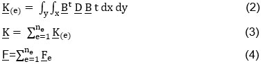
The equation for the domain of the overall system is given by [13];
![]()
When the displacements were found, the strain and stress elements can be determined by using the Stress-Strain (S-S) relations. Now Equation 5 can be re-written as:
![]()
Thermal Loadings
The finite element structure to calculate the temperature distributions T(x,y) at any point of (x, y) can be stated as [13];
![]()
The force element matrix can be found as;
![]()
where the global force vector F can be calculated as:
![]()
Now, the element stiffness matrix becomes:
![]()
For two-dimensional heat transfer the D matrix can be stated as [13];
The temperature of the overall system can be expressed as;
![]()
J-Integral for thermal loading
The equation of the J-integral can be written as [13];
![]()
While in the case of thermal loadings, the J-integral equation is;
![]()
Results and Discussion
Pressurized pipes under thermal boundary conditions are analyzed to investigate the influence of the thermal loadings on the stress distributions and J-integral calculations for different crack length ratios. Internal pressure in the pipe is 10 Mpa and the outer surface at ambient environmental conditions. The outside temperature is 26°C and the heat transfer coefficient inside the pipe is 5000 w. m-2. K-1. The FEM and Fortran 90 program was used to analyze this study. In this study, the result is validated with an analytical solution which was found in the open literature [12]. The analysis was conducted on the pipes to investigate the influence of the surface’s temperature and the influence of the fluid’s temperature for pressurized pipes. Table 1 shows the data used for cases 1, 2, and 3. The stresses and J-integral calculations for three cases with different crack length ratios for thermal and structural boundary conditions are studied. Figure 1 shows the geometry and schematic mesh of the cylinder. For simplification and due to the pipe’s symmetry, just a quarter of the cylindrical pipe was meshed by using 80- quadrilateral 8-node standard element and plain strain conditions for the three cases. Figure 2 shows the displacements, the radial and tangential stresses through the cylindrical pipe. The results are compared with an analytical solution from [12].
Table 1: Case studies parameters.
| Case | Ri (mm) | Ro (mm) | Loading |
| 1 | 70 | 110 | Α |
| 2 | 80 | 100 | α+β |
| 3 | 1.8 | 2 | α+β |
 |
Figure 1: a- a cylindrical pipe, b- a cross-section of the cylindrical pipe, c- the mesh of the cylindrical pipe’s quarter. Click here to View Figure |
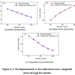 |
Figure 2: a- The displacements, b- the radial stress and c- tangential stress through the cylinder. Click here to View Figure |
Effect of Pressure and Thermal Parameters on Stresses Distribution
Effect of Pressure and Surface’s Temperature
In this study, the effect of the surface’s temperature on stress distributions of pipes is analyzed. The inner surface’s temperature is maintained -100°C while the outer surface of the cylinder is exposed to different temperatures (0, 25, 50, 75 and 100°C) respectively and internal pressure is 10 Mpa. Figure 3 shows the temperatures distributions, the radial stress and tangential stress. It is clear that as the temperature difference increases the convection heat transfer coefficient at one surface also increases. This is due to the proportional relation between the temperature differences and the convection heat transfer coefficient based on Newton’s law.
 |
Figure 3: a- the temperature distribution for different distances, b- a radial variation of the radial stress, c- tangential stresses. Click here to View Figure |
Effect of Pressure and Fluid’s Temperature
The effect of fluid temperature and pressure values on the stresses distributions is studied. The fluid flows inside the pipe at various temperatures while the heat transfer coefficient assumed constant. The fluid’s temperatures changes from 50°C to 150°C. The pressure inside the pipe is 10 Mpa. The heat transfer coefficient is (5000 w. m-2. K-1.). Figure 4 illustrates the temperature distribution, the radial and tangential stresses. It can be observed that the radial and tangential stresses decrease as the temperature of the ambient fluid increases. Also, it can be seen that the temperature differences between the inner and outer surfaces of the pipe decreased when the temperature of the fluid is increased based on Newton’s law of cooling. Therefore, thermal stresses decline with the decrease of the temperature differences due to increasing of the fluid’s temperature.
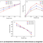 |
Figure 4: (a) temperature distributions (b) radial stresses (c) tangential stresses. Click here to View Figure |
Effect of Pressure and Surface’s Temperature
In this case, the effect of the surface’s temperature and the pressure on the calculations of the values of J-integral and stress intensity factors is investigated. The cylindrical pipe has a radial crack in the inner surface. The J-integral and stress intensity factors for different crack’s length ratios were discussed. The inner surface’s temperature is maintained -100°C while the outer surface of the cylinder is exposed to different temperatures (0, 25, 50, 75 and 100°C) respectively and internal pressure is 10 Mpa. Figure 5 shows the J-integral values and stress intensity factors for a cracked pipe which has different crack lengths. The higher temperature difference existed between the crack tip regions and the outer surface of the cylinder. Thus, the tensile stresses across the pipe increase dramatically and the stress intensity factor values increase for each ratio of a crack length. Then, the values of the J-integral are increased when the crack length ratios increase because of the increase of the stress intensity factors.
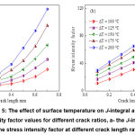 |
Figure 5: The effect of surface temperature on J-integral and stress intensity factor values for different crack ratios, a- the J-integral, b- the stress intensity factor at different crack length ratios. Click here to View Figure |
Effect of Pressure and Fluid’s Temperature on J-integral
The effect of fluid’s temperature and pressure of cracked pipe on stress intensity factor and J-integral was discussed. The cylindrical pipe with a radial crack was subjected to pressure and thermal loadings are studied. The temperatures of fluid inside the pipe changes from 50°C to 150°C. The pressure inside the pipe pressure is 10 Mpa and the heat transfer coefficient is (5000 w. m-2. K-1). Figure 6 illustrates the stress intensity factors and J-integral for different crack length ratios and loadings. The temperature distribution between the inner and outer surfaces of the pipe decreased. Then, lower tensile stresses across the uncracked side are noticed. The value of the stress intensity factor and J-integral decreases when cracking length ratio increases because of the high heat flux through the pipe. The fluid’s temperature increasing will reduce the values of both stress intensity factor and J-integral.
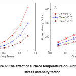 |
Figure 6: The effect of surface temperature on J-integral and stress intensity factor Click here to View Figure |
values (a) The J-integral for different crack ratios (b) The stress intensity factor at different crack length ratios.
Conclusions
In this study, thermal loadings influence on stress analysis and J-integral calculations for pressurized and cracked pressurized pipes were studied. The effect of the surface’s temperature and fluid temperature on stress distribution and J-integral calculations was studied. Thermal stresses and J-integral values were affected by the surface and fluid temperatures of cylindrical pipe with and without cracks. Thermal stresses increase with an increase in the surface temperature by 50%. Moreover, the J-integral value increases nearly 77% with increasing the surface temperature due to the increase of thermal stresses. However, the thermal stresses and J-integral value decreases about 33% with an increase in the fluid temperature.
Acknowledgements
The authors would like to acknowledge the University of Thi-Qar and Engineering college for their support to establish this article.
References
- Cheng,Y. F., Pipeline Engineering, Encycl. Life Support Syst., 1–42
- Kim, W., and Lee, Y.; Yoo, B. , Numerical Evaluation of Stress Intensity Factor for Vessel and Pipe Subjected to Thermal shock ,International Journal of Pressure Vessel and Piping, 1994, 58,215-222.
- Al-Edani, N., Efficient Fracture Mechanics Programming System for Linear and Non-linear Problems Using Finite Element and Boundary Element Methods, D Thesis, Cranfield Institute of Technology School of Mechanical Engineering, England, 1990.
- Lee, Y.; Park, S., J-Integral Under Transient Temperature State Engineering Fracture Mechanics, 1992,43, 931-940.
- Karim, Egab; Hassan Hassan; Ali A. Khalaf; Saad K Oudah; Ameen Nassar; Yeasin Bhuiyan; Amitav Tikadar, Study the Effect of Heat Transfer Coefficient and Thermal Conductivity on Cracked Pipes Carrying Pressurized Fluid, International Journal of Engineering & Technology, 2018.
- Karim Egab; Saad K. Oudah; Ameen Nassar; Hassan Hassan; Yeasin Bhuiyan, Investigation of temperature effect on cracked pressurized pipes, Proceedings of the ASME 2018 International Mechanical Engineering Congress and Exposition IMECE 2018November 9-15, 2018, Pittsburgh, PA, USA.
- Long L.; Iwasaki S.; Yin F.; Nagai K. ,Prediction of Nominal Stress-Strain Curves of a Multi-Layered Composite Material by FE Analysis, Materials Transactions, 2010, 51, 2188-2195.
- Sevecek, O.; Pletz M.; Bermejo R.; Supancic P. ,Analytical Stress-Strain analysis of the laminates with orthotropic (isotropic) layers using Classical Laminate Theory, Materials Center Leoben Forschung GmbH, Presentation, 2011.
- Wang Z.; Wang W.; Wang H.; Hu Y., Stress Analysis on Layered Materials in Point Elastohydrodynamic-Lubricated Contacts, Tribology Letters (Springer), 2009, 35, Issue 3. 229-244, 2009.
- lam, M. T.; Akanda, M.A.S.; Mandal, A.C., Stress analysis of composite lamina having a square hole by finite difference technique, Proceedings of International Conference on Mechanical & Manufacturing Engineering,2008, Johor Bahru, Malaysia, May 21-23,1-6.
- K. Y ; Park. J. S, J-Integral Under Transient Temperature State, Engineering Fracture Mechanics, 1992,.43, 931-940.
- D, Evaluation Fracture Mechanical Parameters of a Thermally Loaded Structures, Scientific Technical Review, 2008, LVIII, N. 2, 27-31.
- Z. W ; Zhou. Y. H, Fracture Behaviors Induced by Thermal Stress in an Anisotropic Half Plane Superconductor, Physical Letters A, 2008,372, 5261-5264.
- D;Biswas. K, Path Independent Integral J_ Factor for Circular Arc Crack: FEM-Investigation Under Mechanical and Thermal Loads, Finite Element in Analysis and Design, 2009,45, 369-376.
- Q.Wang;S.S. Sun; A.J. Li, S.J. Zhou ,The characteristics of J-integral under biaxial stressing, International Journal of Pressure Vessels and Piping, 2000,77, 159–165.
- J.H.Kuang;Y.C.Chen,The values of J-integral within the plastic zone, Engineering Fracture Mechanics,1996, 55, Issue 6, 869-881.

This work is licensed under a Creative Commons Attribution 4.0 International License.
![]()
A New Edition of Web of Science
Journal Impact Factor
2022: 0.5
Five Year: 0.8
Journal is Indexed in

Cabells Whitelist
![]()


