Development of a Solid-State Magnesium-Persulfate Based Rechargeable Battery
Shirley T. Palisoc1,2, Jozel John P. Salvacion1, Julita C. Robles3 and Michelle T. Natividad*1,2
1Department of Physics, De La Salle University, 2401 Taft Avenue, Manila, 922, Philippines.
2Censer, De La Salle University, 2401 Taft Avenue, Manila, 922, Philippines.
3Department of Chemistry, De La Salle University, 2401 Taft Avenue, Manila, 922, Philippines.
Corresponding Author E-mail: michelle.natividad@dlsu.edu.ph
DOI : http://dx.doi.org/10.13005/ojc/350242
Article Received on : 01-02-2019
Article Accepted on : 27-03-2019
Article Published : 26 Apr 2019
Several coin cells with cathode materials ranging from stainless steel, magnesium persulfate, and magnesium persulfate/reduced graphene oxide (rGO), as well as a novel electrolyte, were fabricated and assembled. They were characterized using scanning electron microscopy (SEM), energy dispersive x-ray spectroscopy (EDX), and voltammetry to determine surface morphology, elemental composition, and electrochemical characteristics, respectively. The amount of the additive, rGO, was verified by analyzing the current response after 10 consecutive scans via cyclic voltammetry. The optimum amount which only had a 19% decrease from cycle 2 to cycle 9 was from the cathode electrode which had 4mg rGO. However, galvanostatic charge-discharge measurements showed that the coin cells had no ability to hold the charge after cycling. The coin cell which contained the optimized cathode electrode was dismantled for further surface and elemental analysis. After a scan, some of the cathode material was converted to its reduction product magnesium sulfate (MgSO4) and failed to revert back to its original persulfate form which signified irreversibility. Contaminants were found on the surface of the anode and corrosion were observed on the surface of the current collector which denotes instability of the components with the chosen electrolyte. The reactivity of the components with each other was also predicted by previous studies.
KEYWORDS:Energy Dispersive X-Ray Spectroscopy; Magnesium Persulfate; Reduced Graphene Oxide; Scanning Electron Microscopy; Voltammetry
Download this article as:| Copy the following to cite this article: Palisoc S. T, Salvacion J. J. P, Robles J. C, Natividad M. T. Development of a Solid-State Magnesium-Persulfate Based Rechargeable Battery. Orient J Chem 2019;35(2). |
| Copy the following to cite this URL: Palisoc S. T, Salvacion J. J. P, Robles J. C, Natividad M. T. Development of a Solid-State Magnesium-Persulfate Based Rechargeable Battery. Orient J Chem 2019;35(2). Available from: https://bit.ly/2DLaT3F |
Introduction
In the evolution of cutting edge technology, the search for state of the art alternative sources of energy is of utmost importance. There is a vital need for a higher capacity, faster charging, and economically, as well as, ecologically favorable battery. Current Lithium-ion batteries (LIB) still pose several problems as far as safety, efficiency, and cost are concerned.1 Magnesium (Mg) is one of the top contenders to replace Lithium (Li) because not only is it relatively similar to the ionic radius of Li (0.74Å vs 0.68Å, respectively) but it is also shown to be superior over Li in several aspects which include: 1) cost due to natural abundance (~5% abundance on the Earth’s crust), 2) operational safety & elemental stability as Mg favors the formation of a smooth surface, thereby eliminating the risk of dendrite formation, and its compounds are usually non-toxic, and 3) theoretical volumetric capacity (Mg ~3832 mAh cm-3 vs. Li ~2061 mAh cm-3 ).1-3, 4-5 On the other hand, Mg has a lower potential (~0.7V lower vs Li), unique properties that limits the possible electrolyte-cathode pair, and slow insertion kinetics due to strong electrostatic interactions.2,4
The investigation for a stable Mg based battery is still in its conception stage because of setbacks with Mg as a battery component.3 The unwieldy interaction between the elemental Mg anode and electrolyte results in the formation of an impermeable surface layer, usually in the form of Mg(OH)2 or MgO, between the anode and its environment that makes the reversibility of the Mg deposition process impossible.1 The reason for the formation of an impermeable surface is not fully understood; however, it is proposed that it is a byproduct of electrolyte degradation.3 In contrast, in Li batteries, this surface layer, or solid electrolyte interface, aids the ionic diffusion and prevents electrolyte degradation.
On the other hand, with Mg as a cathode, the possible challenges are: 1) the slow diffusion rate of the Mg2+ ions back to the anode and 2) its structural instability. The sluggish diffusion rate results to a relatively slow reversibility rate. The structural stability of the cathode is responsible for maintaining the pathway for the Mg2+ ion transport.3 These problems hinder the development and modification of Mg cathodes for industrial and commercial use. Furthermore, the choice of cathode, namely MgS2O8, in this study was not readily available commercially and thus it was synthesized using methods similar to the production of other persulfate compounds.
The complications brought by Mg electrolytes are low stability against electrochemical oxidation, poor compatibility with the magnesium metal anode, and undesirable chemical interactions with the cathode. These setbacks result to low operating voltage, inefficient reversibility, and incompatibility with several cathode materials that cause corrosion.2-3,6
There are attempts7 on overcoming the aforementioned problems such as studying different electrolytes and their compatibility with Mg, and it was found out that Mg metal reacts with most aprotic solvents (esters, carbonates, etc.), and anions that are commonly used which cause build-up of impermeable surfaces which inhibit electron flow.8 The sluggish diffusion of Mg2+ can be overcome by coming up with structural designs which enable faster Mg2+ diffusion which in turn give way for discovering Mg battery cathodes working at higher voltages.3 There is also a need for discovering halide-free electrolytes with high reductive stabilities which can be used for Mg based batteries.8
In this study, magnesium persulfate-reduced graphene oxide (MgS2O8/rGO) cathode electrode was synthesized. As magnesium persulfate was not readily available in the market, it was fabricated using the protocol of Ropp9 in the production of barium persulfate with modifications to attain the desired product. To date, there is no literature on the properties of magnesium persulfate as to its crystal structure, melting point, boiling point, and reactivity, among others. A polymer-based electrolyte was also synthesized using a magnesium hexafluorophosphate [Mg(PF6)2] in lieu of lithium hexafluorophosphate [LiPF6]. The choice of components were based on the theoretical framework and suggestions laid out by Disselkamp.10
The primary reason of choosing the cathodic materials, or battery components for that matter, was the lack of experimental investigation on Disselkamp’s theoretical modification to a successful glassfiber mat based lithium-ion battery study.10 The choice of additive for the cathode, on the other hand, was based on how rGO is an exemplary enhancer for electrodes, and due to the promising results shown by Sheha’s study11 on the relative effect on electrochemical performance of rGO on TiO2 as cathode materials for magnesium batteries as well as the positive results of Vinayan et al.12
Cyclic voltammetry (CV) and chronopotentiometry (CP) using a BST8 Potentiostat/Galvanostat were done to determine the electrochemical properties such as capacity limits, voltage limits, and reversibility of the fabricated battery while a scanning electron microscope equipped with EDX capabilities (SEM-EDX) was used to determine the battery’s surface morphology, specifically before and after scanning to check if an impermeable layer was formed on the anode, as well as to determine its specific elemental composition. X-ray powder diffraction (XRD) using the Terra Mobile XRD System and XPowderX software were utilized to determine the crystallographic properties of magnesium persulfate.
Methodology
Chemicals and Reagents
The chemicals and reagents for the fabrication of the electrode required magnesium powder (~99% purity), reduced graphene oxide (rGO) (>99% purity), magnesium hydroxide (Mg(OH)2) (95% purity), and ammonium persulfate ((NH4)2S2O8) (99.9% purity). Magnesium hexafluorophosphate (Mg(PF6)2) (~99% purity), ethylene carbonate ((CH2O)2CO) (>99% purity), dimethyl carbonate ((CH3O)2CO) (99%), and ethyl methyl carbonate (C4H8O3) (99%) were used to produce the electrolyte solution while poly-vinylidene fluoride [PVDF], glass fiber mat (GFM), and N,N-dimethylacetamide (>99% purity) were used for the gel polymer electrolyte.
Instrumentation
The equipment that were used in this study are the following: sidEntry™ glove box, vacuum oven, BST8 potentiostat/galvanostat, BOSCH SAE200 electronic balance, JEOL 5300 scanning electron microscope (SEM), focused ion beam/field emission electron microscope (FIB/FEM) coupled with energy dispersive X-ray spectrometer (EDX), BANDELIN SONOREX sonicator bath, carver hydraulic press, and other glassware.
Electrolyte Preparation
The electrolyte preparation in this study was based on Disselkamp’s10 theoretical modification of the lithium based electrolyte preparation by Zhu et al.13 One molar, 1M, of [Mg(PF6)2] was dissolved in ethylene carbonate, dimethyl carbonate, and ethyl methyl carbonate with 1/1/1 weight ratio for the electrolyte solution. Due to the relative volatility of EMC with moisture in the air, all preparations were done in a glovebox with Ar gas stream to remove volatile impurities.
The glass fiber mat separators were weighed before cast coating both sides with poly-vinylidene fluoride, of molecular weight 534,000 and 0.600 g, and dissolved in N,N-dimethylacetamide (7mL). Each side was air-dried before coating the other with the PVDF solution. After both sides were dried in room temperature, the weight was found to increase by an average of ~55%. The weight increase was from an average weight of 16.65 mg to an average weight of 25.82 mg before and after coating, respectively. The separators were then vacuum dried at 80°C for 48 hours.
The dried PVDF-coated GFM was soaked with the prepared electrolyte solution. The soaking process was done for 12 hours in a glovebox with Ar gas stream.
Cathode and Anode Preparation
The working anode is pure magnesium metal (in powder form). Powdered magnesium was pressed using a Carver Hydraulics Press. The cathode, on the other hand, was MgS2O8 electrode with reduced graphene oxide as the electrode enhancer. The protocol that was followed to produce MgS2O8 is in consonance with the procedure in producing barium persulfate (Ba2S2O8) of Ropp.9 Instead of using barium hydroxide [Ba(OH)2], magnesium hydroxide [Mg(OH)2] was utilized to react with a saturated solution of ammonium persulfate [(NH4)2S2O8]. This reaction produced ammonia and the desired product, MgS2O8. The ammonia evaporated, naturally. The solution was filtered thrice to remove the liquid precipitate to isolate the MgS2O8 paste and placed in a vacuum oven to produce powdered crystals of MgS2O8. Using 200.5mg of MgS2O8 per pellet, a total of seven (7) 10 mm pellets were produced with each successive pellet having an increment of 1 mg of rGO than the previous starting from 0mg. Pelletizing was also done using the carver hydraulic press.
Characterization
Surface analysis of the anode, and separator were carried out with the use of JEOL 5300 SEM and the FIB-FESEM. Elemental analysis via energy dispersive x-ray spectroscopy of the cathode was also performed. Cyclic voltammetry and chronopotentiometry were carried out using BST8 Potentiostat. Tests were done in a three (3) electrode system with the cathode acting as the working electrode and the anode acting as both the counter and reference electrodes.
Results and Discussion
Morphology
Figure 3.1 (a) to (d) show the structure of the glass fiber mat separator before coating with any of the solutions. Each individual strand may be seen clearly and appears to be smooth indicating no contamination nor any extraneous substance on any of the strands observed.
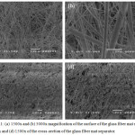 |
Figure 3.1: (a) 1500x and (b) 5000x magnification of the surface of the glass fiber mat separator. (c) 750x and (d) 1500x of the cross-section of the glass fiber mat separator. |
Figure 3.2 show how the PVDF solution fused with the strands of the separator. The PVDF solution made the strands appear more defined in the images on the top row while filling some of the gaps. As shown in the cross section, it was confirmed that even the center part of the separator absorbed the PVDF solution. These results are comparable to Zhu et al.13
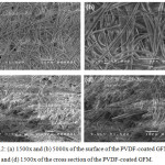 |
Figure 3.2: (a) 1500x and (b) 5000x of the surface of the PVDF-coated GFM. (c) 750x and (d) 1500x of the cross section of the PVDF-coated GFM. |
The surface of the electrolyte-soaked separator showed that each individual strand could no longer be clearly distinguished from each other. The same could be said with the cross section of the separator. The electrolyte solution solidified and filled most of the gaps and voids previously present in the separator.
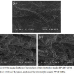 |
Figure 3.3: (a) 1500x magnification of the surface of the electrolyte soaked PVDF-GFM. (b) 750x and (c) 1500x of the cross-section of the electrolyte soaked PVDF-GFM. |
Figure 3.4 shows the surface morphology of the pelletized magnesium powder at 1000x magnification. The surface is relatively smooth and that no clumps are observed on its surface.
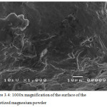 |
Figure 3.4: 1000x magnification of the surface of the pelletized magnesium powder. |
Figure 3.4 (a) to (c) clearly show lumps that were not previously seen on the surface of the anode prior to cycling. These clumps resulted from the redox reaction that occurred during the cycling of the battery. The irreversibility of the system is attributed to the presence of these lumps.
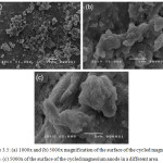 |
Figure 3.5: (a) 1000x and (b) 5000x magnification of the surface of the cycled magnesium anode. (c) 5000x of the surface of the cycled magnesium anode in a different area. |
Figure 3.6 show the surface morphology of the fabricated cathode. It can be seen that the electrode has a definite crystal structure as exemplified by images (f) and (g). It suggests a monoclinic crystal structure. This will be elaborated in the XRD analysis.
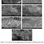 |
Figure 3.6: (a) and (b) 2000x magnification of the surface on different sites of the MgS2O8 cathode, (c) and (d) 5000x magnification of the surface on different sites of the MgS2O8 cathode, (e) and (f) 10000x magnification of the surface on different sites of the MgS2O8 cathode, (g) 20000x magnification of the surface of the MgS2O8 cathode. |
Elemental Composition of the Cathode
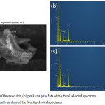 |
Figure 3.7: (a) Observed site, (b) peak analysis data of the third selected spectrum and (c) peak analysis data of the fourth selected spectrum. |
Figure 3.7 (b) shows an almost exact fit to the theoretically computed wMg/wS/wO (1:2.7:5.3) ratio for MgS2O8. The excess in wt% is attributed to the rGO additive and carbon paper used to test the sample. Figure 3.7 (c) also shows a similar result with a slightly lower S content. This means that there are other species present in the sample due to its reduction product, MgSO4.
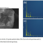 |
Figure 3.8: (a) Observed site, (b) peak analysis data of the first selected spectrum and (c) peak analysis data of the third selected spectrum. |
Figure 3.8. (b) and (c) show the presence of MgS2O8 throughout the sample. A slight variation in the concentration of S and O may also be observed which can be attributed to the presence of other species in the sample such as its reduction product, MgSO4.
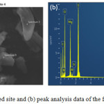 |
Figure 3.9: (a) Observed site and (b) peak analysis data of the first selected spectrum. |
Figure 3.9(b) does not show the presence of MgS2O8. The presence of the elements in the supposed MgS2O8 are below the calculated ratio as seen in Fig. 3.7 and 3.8 which points out to the presence of MgSO4 throughout this site. This confirms that after cycling, some of the cathode material failed to revert back to its persulfate form and that the lost material may be observed in the anode.
Cyclic Voltammetry
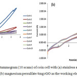 |
Figure 3.10: Cyclic voltammogram (10 scans) of coin cell with (a) stainless steel (SS) as the working electrode and (b) magnesium persulfate/4mg rGO as the working electrode. |
Cyclic voltammetry measurements were done to test the oxidative stability, as well as, the electrochemical window of the produced electrolyte. All tests to determine the electrochemical window of the battery were done with the range of -1.5V to +3.6V with a scan rate of 50mV/s for 10 cycles. Tests to determine the best electrode, on the other hand, were done with the range of 0V to +4.5V for 10 cycles to simulate the possible voltage ranges of the battery as calculated theoretically. The open circuit voltage (OCV) of all the tested batteries was found to be ̴ 0.9V.
Stainless steel (Fig. 3.10a) was used as the control to determine the electrochemical window of the electrolyte. The electrolyte’s electrochemical window was found to be >5V from the potential range of -1.5V to +3.6V. Beyond 3.6V, a potential dip appeared which indicate that oxidation occurred. Measurements below -1.5V were also performed. However, during the negative to the positive cycle tests, -1.5V was the optimal starting point as it produced more reliable and stable data compared to lower potentials.
The selection of the best electrode was done by comparing the relative change of current response after each cycle. Adding 4mg of rGO resulted to the cell having little current response variation for the succeeding cycles. This is illustrated in Fig. 3.10b. Thus, 4mg of rGO was selected as the best cathode for this study. Magnesium persulfate / 4mg rGO had a current response variation of about 19% from cycle 2 to cycle 9, cycles with the highest and lowest values respectively.
Chronopotentiometry
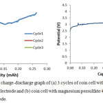 |
Figure 3.11: Galvanostatic charge-discharge graph of (a) 3 cycles of coin cell with bare magnesium persulfate as the working electrode and (b) coin cell with magnesium persulfate/4mg rGO as the working electrode. |
Chronopotentiometry was employed to determine the capacity of the battery. Bare MgS2O8 was used as the control to determine the effects of the additive, rGO, in the battery system. Testing was proven to be difficult for no data was gathered for 1mg, 2mg, 3mg, 5mg, and 6mg. When capacity cyclingstarted, the potential response immediately exceeds the maximum theoretical potential while charging and drops below the minimum assigned potential while discharging which suggested high interfacial resistance as previously seen in Shterenberg et al.14
For the bare cathode, as shown in Fig. 3.11(a), a 200.5mg sample may be cycled up to 0.25mAh which is way below its calculated value of 55.94 mAh for the 200.5mg sample. However, it appears to have no capability to hold charge since during the discharging step, the potential immediately drops below the assigned potential threshold. Furthermore, succeeding charging cycles showed only a fraction of the value of the first cycle indicating the decline in useable cathode material.
For the MgS2O8/4mg rGO cathode as shown in Fig. 3.11(b), it was found that the MgS2O8/4mg persulfate/rGO sample may only be cycled once to about 0.065mAh and further cycles will not hold charge as compared to the bare electrode.
The SEM (cf Fig. 3.5 and 3.6) results for the cycled MgS2O8/4mg rGO cathode show that contaminants appeared on the surface of the anode and traces of MgSO4 may be found on the cathode indicating irreversibility of the redox reaction of the system. The contaminants on the anode inhibit the reversible process resulting to failure to hold charge.
Another factor for the irreversible process is the relative instability of the components in the presence of the Mg(PF6)2 electrolyte. Shterenberg et al.14 proved that pure hexafluorophosphate [PF6–] solution, which has the characteristic of having no chlorides or stabilizing agents, inhibits Mg cycling or discharging of the battery.
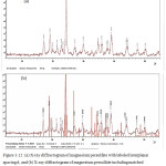 |
Figure 3.12: (a) X-ray diffractogram of magnesium persulfate with labeled interplanar spacing d, and (b) X-ray diffractogram of magnesium persulfate including matched peaks with a monoclinic mineral boussingaultite. |
X-Ray Powder Diffraction
Crystallographic Properties
Upon comparison with the monoclinic crystal structure of boussingaultite.15 the peaks show a significant similarity with each other as shown in Figure 3.12(b). Furthermore, the experimental values of the interplanar spacing, d, shows a good fit with the theoretical values of the mineral when using the wavelength of cobalt (λco=1.78897Å) calculated from Bragg’s Law16 as seen in Table 3.1. The data show an average percent error of 0.285% with no value exceeding an error of 0.7%.
The standard found in15 used copper as their anode material, and thus a conversion of values utilizing the wavelength of cobalt (the anode material used in the Terra Mobile XRD System) was deemed necessary.
Table 3.1: Interplanar spacing, d, values.
|
(hkl) |
(001) |
(011) |
(130) |
(031) |
(-231) |
(012) |
(-141) |
(-321) |
(022) |
(-232) |
(-142) |
(420) |
|
Experimental |
5.964 |
5.349 |
3.776 |
3.444 |
2.978 |
2.886 |
2.761 |
2.737 |
2.666 |
2.380 |
2.210 |
2.104 |
|
Theoretical |
5.934 |
5.369 |
3.799 |
3.428 |
2.972 |
2.888 |
2.766 |
2.736 |
2.684 |
2.383 |
2.210 |
2.100 |
|
% Error |
0.5056 |
0.3725 |
0.6054 |
0.4667 |
0.2019 |
0.0692 |
0.1808 |
0.0365 |
0.6706 |
0.1259 |
0 |
0.1905 |
|
% Difference |
0.5043 |
0.3732 |
0.6073 |
0.4667 |
0.2017 |
0.0693 |
0.1809 |
0.0365 |
0.6729 |
0.1260 |
0 |
0.1903 |
Conclusion
Fabrication and characterization of every component of a Mg||MgS2O8 based battery was successful. Scanning electron microscopy analysis of the cathode electrode confirms the synthesis of the desired substance, MgS2O8, which was used as the primary component for the cathode. It was determined through cyclic voltammetry that adding 4mg rGO made the cyclability of the electrolyte relatively more stable, but not necessarily the stability of the battery system as a whole. It was observed with the use of galvanostatic charge-discharge tests that the addition of 4mg rGO had detrimental effects on the capacity of the electrode. The operating voltage of the battery was found to be about 0.9V which was way below the theoretically calculated value of 4.382V. This can be attributed to the high interfacial resistance caused by the impurities present in the electrode.
Scanning electron microscopy analysis on both the cathode and the anode showed the presence of unwanted byproducts after capacity cycling. Furthermore, upon inspection of the current collector after cycling, corrosion developed. The negative results in this study are attributed to these byproducts as well as the corrosion present in the current collector. X-ray powder diffraction points out that the crystal structure of magnesium persulfate is monoclinic. The interplanar spacing, d, values show an average percent error of 0.2855% with no value having an error that exceeds 0.7%.
The choice for compatible components that would harmoniously interact with each other during all measurements are yet to be found. Subsequently, this study crosses out one of the possible choice of components to be tested but brings out more possible component combinations for future studies.
Acknowledgments
This work was supported by the University Research Coordination Office (URCO) of De La Salle University, Manila, Philippines.
References
- Yoo, H.D.; Shterenberg, I.; Gofer, Y.; Gershinsky, G.; Pour, N.; Aurbach, D. Energ. Environ.l Sci. 2013, 6, 2265-2279.
- Muldoon, J.; Bucur, C.; Oliver, A.; Sugimoto, T.; Matsui, M.; Kim, H.S.; Allred, G.; Zajicek, J.; Kotani, Y. Energ. Environ. Sci. 2012, 5, 5941-5950.
- Mohtadi, R.; Mizuno, F. Beilstein J. Nanotechnol. 2014, 5, 1291-1311.
- Vinayan, B.P.; Zhao-Karger, Z.; Diemant, T.; Chakravadhanula, V.; Schwarzbuerger, N.; Cambaz, M.; Behm, R.J.; Kubel, C.; Fichtner, M. Nanoscale 2016, 8, 3296-3306.
- Su, S.; NuLi, Y.; Huang, Z.; Miao, Q.; Yang, J.; Wang, J. ACS Appl. Mater. Inter. 2016, 8, 7111-7117.
- Mohtadi, R.; Matsui, M.; Arthur, T.; Hwang, S.J. Angew Chem Int Ed Engl. 2012, 5, 9780-9783.
- Song J., Sahadeo E., Noked M., Lee S. B. J. Phys. Chem. Lett. 2016, 7, 1736–1749.
- Kim, D. Y., Lim, Y., Roy, B., Ryu, Y. G., Lee, S. S. Roy. Soc. Chem. 2014, 16, 25789-25798
- Ropp, R.; Encyclopedia of the Alkaline Earth Compounds, Royal Soc. Chem. 2012, London, U.K.
- Disselkamp, R. J. Power Energy Eng. 2015, 3, 9-13.
- Sheha, E. Graphene, 2014, 3, 36-43.
- Vinayan, BP, Zhao-Karger, Z., Diemant, T., Chakravadhanula, V., Schwarzbuerger, N., Cambaz, M., Behm, RJ., Kubel, C., Fichtner, M. Nanoscale, 2016, 8, 3296-3306.
- Zhu, Y.; Wang, F.; Liu, L.; Xiao, S.; Yang, Y.; Yuping, W. Sci. Rep. 2013, 3, 1.
- Shterenberg, I.; Salama, M.; Gofer, Y.; Aurbach, D. Langmuir 2017, 33, 9472-9478.
- Margulis, T.N.; Templeton, D.H. Z. Kristallogr. Cryst. Mater. 1962, 107, 344.
- Bragg, W. H.; Bragg, W. L. R. Soc. 1913, 88, 428.

This work is licensed under a Creative Commons Attribution 4.0 International License.


