Theoretical Investigation of Application of Combining Pristine C60 and Doped C60 with Silicon and Germanium Atoms for Solar Cells ; A DFT Study
Leila Hojatkashani
Department of Chemistry, College of Basic Sciences, Yadegar-e-Imam Khomeini (RAH) Branch, Islamic Azad University. Tehran. Iran.
Corresponding Author E-mail: L.Hojat@yahoo.com
DOI : http://dx.doi.org/10.13005/ojc/350130
Article Received on : 21-12-2018
Article Accepted on : 02-02-2019
Article Published : 21 Feb 2019
Solar energy and its conversion to electricity is an important research in the last decade. Solar cells are consist of a p-type semiconductor as donor and an n-type semiconductor as acceptor. Organic polymers as organic semiconductors are used in an organic solar cell. This research is a theoretical investigation of fullerene C60 as donor and C60 doped derivatives with Silicon and Germanium atoms as acceptors for basic structure of a solar cell. This research is done not only with using related equations but also with investigating theoretical UV-VIS spectrum of the chosen donors-acceptors and their absorption wavelengths, oscillator strength and maximum coefficient absorptions of these solar cells.
KEYWORDS:Acceptor; Absorption Wavelengths; C60; Donor; Fill Factor; HOMO and LUMO Orbitals; Maximum Coefficient Absorptions; Organic Solar Cell; Open-Circuit Voltage; Oscillator Strength; Power Output; Short-Circuit Current Density; UV-VIS Spectrum
Download this article as:| Copy the following to cite this article: Hojatkashani L. Theoretical Investigation of Application of Combining Pristine C60 and Doped C60 with Silicon and Germanium Atoms for Solar Cells ; A DFT Study. Orient J Chem 2019;35(1). |
| Copy the following to cite this URL: Hojatkashani L. Theoretical Investigation of Application of Combining Pristine C60 and Doped C60 with Silicon and Germanium Atoms for Solar Cells ; A DFT Study. Orient J Chem 2019;35(1). Available from: https://bit.ly/2BMLYvi |
Introduction
Solar energy is an important energy sources nowadays. The sun gives to the earth surface in so much energy in a day that it could be enough to cover the daily need of the population of our planet. Photovoltaic devices and solar cells are the most simple and efficient conversion of the solar energy to electricity.1
Organic solar cell research has developed during the past 30 years, but in the last decade it has attracted scientific and economic interest because of a rapid increased need for electrical power. Scientists have achieved new materials, improved materials engineering, and more advanced device structures.2 The search for new materials has been extended into the field of organic polymers , inorganic and semi conducting molecules that their optical, electrochemical and electrical properties can offer wide conversion of the solar energy to electricity. Organic semiconductors are used to be described as conjugated oligomers or polymers which are able to transporting charge carriers. Holes and electrons in p-orbitals are the typical charge carriers in organic semiconductors. Charge transport depends on the movement of the charge carriers to from one molecule to another and depends on the energy gap between highest occupied molecular orbital (HOMO) and lowest unoccupied molecular orbital (LUMO) levels.3
The basic operation of solar cells is summarized in four steps which are illustrated in figure (1): 1- photon absorption leading to exciton generation; 2- exciton diffusion to a donor/ acceptor heterojunction; 3- exciton dissociation at a heterojunction to form geminate pairs; 4- carrier transport and carrier extraction at the electrodes.4
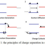 |
Figure 1: The principles of charge separation in solar cell.4 |
Organic solar cells are basically consist of a p-type semiconductor as donor and a n-type semiconductor as acceptor. At the donor–acceptor interface, charges are separated after photo-induced charge transfer from the electron donor to the electron acceptor. Figure (2) shows a schematic frontier orbital energy levels and the basic fundamental steps which happens in a typically Organic solar cell.3
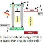 |
Figure 2: Frontier orbital energy levels in donor-acceptor layers of an organic solar cell.3 |
Bulk heterojunction (BHJ) structure is the most successful method for a solar cell can be a blend of donor and acceptor materials with a bicontinual phase separation.5 Many fullerene-based molecules can be used in organic photovoltaic devices for the reason that fullerene is good p-electron acceptor which can be connected with other organic molecules.6 This observation lead us to the C60 molecule and how there can be increase in photo-conductivity properties upon addition of C60 to other conjugated polymers.
The buckminster fullerene C60 and its derivatives are strong electron acceptors.2
In this paper, First, HOMO and LUMO levels a fullerene C60 and its doped with one, two and three Silicon and Germanium atoms are calculated and compared. Then, with equations and approximate calculations, suitable donors and acceptors for organic solar cell will be selected. In the end, The theoretical UV-VIS absorptions of these donors/acceptors are used to confirm of calculated results.
Computional method
DFT functional methods PBE and HCTH with 6–31+G(d) basis set are used to calculate HOMO and LUMO levels a fullerene C60.7 and its doped complexes configurations which contain 1-3 doped Silicon atoms and 1-3 doped Germanium, respectively. Silicon and Germanium are semiconductors chosen from forth group of the periodic table of elements. All calculations were performed by package GAUSSIAN 03. Vibration frequencies were also calculated at the same level to confirm that all the stationary points correspond to true minima on the potential energy surface. Td=NSTATES=10 is used for determination theoretical UV-VIS absorptions of donors/acceptors as solar cells.
Two factors are important to select among the calculated HOMO and LUMO levels for the solar cell. First, the band gap of approximately 0.3–0.4 eV between the LUMO of the donor and the LUMO of the acceptor is necessary to ensure efficient exciton dissociation at the D/A interface.3 Second, for commonly large band gap of organic materials and small absorption range, a LUMO–HOMO difference (E gap) of 1.1 eV of the donor can show good results.4
Results and Discussion
Calculation HOMO and LUMO levels
In the first step of this work, HOMO and LUMO levels of C60 and its doped derivatives such as C59Si, C58Si2, C57Si3, C59Ge, C58Ge2, C57Ge3 and C58GSi is calculated with DFT functional methods PBE and HCTH. The results are shown in tables (1), (2), (3) and (4).
The calculated E gaps in table (1) Shows a E gap of 1.65( PBE method) and 1.68 (HCTH method) for C60. Titus A. Beu, Jun Onoe, and Akira Hida have calculated The E gap of C60 with these two method and reach the same results.7 LUMO–HOMO difference shows that C60 is not a suitable for a donor compound, so as it was said before. C60 is considered as an acceptor. Tables (2) and (3) show us that doping C60 with semiconductor atoms such as Silicon and Germanium can descries their band gaps which are around 1.1 eV and can be considered as assumed donors in the solar cell.
The second factor, as it was said, is the difference between the LUMO of the donor and the LUMO of the acceptor which must be 0.3–0.4 eV. The calculated LUMOs with PBE and HCTH methods in tables1, 2 and 3 show us that the best candidates for donor compounds are C59Si, C59Ge. The differences between of LUMOs for C58Ge2 and C60, C58GeSi with C60 both with PBE and HCTH methods are near 0.3 eV, so they can be considered as candidates for donor compounds.
Table 1: HOMO and LUMO energy levels and Egap of C60.
| Compound | Method | HOMO(eV) | LUMO(eV) | E gap |
| C60 | PBE | -5.86 | -4.21 | 1.65 |
| C60 | HCTH | -5.97 | -4.29 | 1.68 |
Table 2: HOMO and LUMO energy levels and Egap of doped C60 with Silicon.
| Compound | Method | HOMO(eV) | LUMO(eV) | E gap |
| C59Si | PBE | -5.69 | -4.51 | 1.18 |
| C59Si | HCTH | -5.78 | -4.59 | 1.19 |
| C58Si2 | PBE | -5.52 | -4.45 | 1.07 |
| C58Si2 | HCTH | -5.61 | -4.52 | 1.09 |
| C57Si3 | PBE | -5.43 | -4.26 | 1.17 |
| C57Si3 | HCTH | -5.43 | -4.26 | 1.17 |
Table 3: HOMO and LUMO energy levels and Egap of doped C60 with Germanium.
| Compound | Method | HOMO(eV) | LUMO(eV) | E gap |
| C59Ge | PBE | -5.72 | -4.59 | 1.13 |
| C59Ge | HCTH | -5.80 | -4.67 | 1.13 |
| C58Ge2 | PBE | -5.47 | -4.50 | 0.97 |
| C58Ge2 | HCTH | -5.55 | -4.57 | 0.98 |
| C57Ge3 | PBE | -5.32 | -4.25 | 1.07 |
| C57Ge3 | HCTH | -5.39 | -4.31 | 1.08 |
Table 4: HOMO and LUMO energy levels and Egap of doped C60 with Silicon and Germanium.
| Compound | Method | HOMO(eV) | LUMO(eV) | E gap |
| C58GeSi | PBE | -5.53 | -4.50 | 1.03 |
| C58GeSi | HCTH | -5.61 | -4.57 | 1.04 |
Theoretical Determination of Performance of Donor-Acceptor
Calculation of Voc
VOC (open-circuit voltage) represents the maximum voltage measured in a solar cell, which depends mainly on the energetic levels of frontier orbitals of the used organic material. It means the energy difference of the HOMO level of the donor (D) and the LUMO level of the acceptor (A).3 The parameter Voc can be calculated by the empirical equation.
Voc =(1/e)(|EH(D)|−|EL(A)|)−0.3 V (1)
e, EH(D) and EL(A) are the elementary charge, the HOMO energy of donor and the LUMO energy of acceptor, and 0.3 V is an empirical factor for efficient charge separation.8 Ac The computed values of Voc for the chosen donors – acceptors calculated by equation (1) are listed in table 5.
Determination of Jsc
JSC (short-circuit current density) represents the maximum current that could be obtained in a solar cell. Calculation of Jsc is a great importance for the further improvement of a organic solar cell. In this research for determining Jsc, the incident light intensity dependence of Jsc is used. A power law dependence of Jsc upon light intensity I is reported which is represented in equation (2).
![]()
where α ranges typically from 0.85 to 1 for polymer/ fullerene based solar cells.9 OSCs are typically characterized under 1000 W/m2 light of AM 1.5 solar spectrum and temperature 25°C.3 According to equation (2), Jsc varies between 354.81 W/m2 and 1000 W/m2 . In this work, the average for Jsc is considered which is 677.4 W/m2.
Determination of (FF) and Power Output (Pout)
The fill factor (FF) describes the quality of the solar cell and is determined by the photogenerated charge carriers and the fraction thereof that reaches the electrodes.8 For the FF calculation under ideal conditions, an approximation can be expressed as:
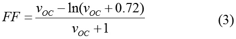
where VOC is the dimensionless voltage Voc and can be calculated by equation (4)
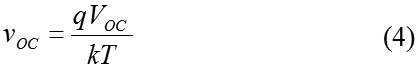
Here k, T and q are the Boltzmann constant, the temperature (300 K) and the elementary charge, respectively.10 The last step in theoretical determination of efficiency of the donor-acceptors candidates for organic solar cells is calculating power output for each donor- acceptor which is calculated by equation (5).3
Pout = VOC × JSC × FF (5)
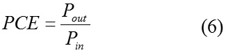
If the standard light intensity (1000 W/m2 light of AM 1.5 solar spectrum) considered as the input power density ( Pin) , the power conversion efficiency (PCE) of the solar cell and can be calculated as equation (6).4
The calculated VOC fill factor, power output and power conversion efficiency of solar cells consist of C60 as acceptor and C60 doped derivatives as donors are listed in table 5.
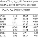 |
Table 5: The computed values of Voc, VOC fill factor and power output for C60 as acceptor and C60 doped derivatives as donors. |
Study of theoretical UV- VIS spetrums
In the next step of this research, with using Td=NSTATES=10, UV- VIS spectrums of C60, C59Si, C59Ge, C59Si/C60, C59Ge/C60, C58Ge2/C60 and C58GeSi/C60 are calculated. These spectrums shows parameters such as absorption wavelengths , oscillator strength and coefficient absorption of these derivatives and donors/acceptors which can be compared.
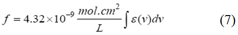
Oscillator strength which represents the average number of electrons per atom that can be excited by the incident radiation. It is an important factor for providing the relative strength of electron transition and can be related with the molar absorption coefficient (ε) as a function of frequency (equation 7). Oscillator strength ranges between 0 and 1.11
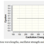 |
Figure 3: Calculated absorption wavelengths, oscillator strength and coefficient absorption of C60. |
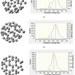 |
Figure 4: Calculated absorption wavelengths, oscillator strength and coefficient absorption of (a) C59Si (b) C59Ge, (c) C58Ge2. |
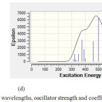 |
Figure 5: Calculated absorption wavelengths, oscillator strength and coefficient absorption of (d) C59SiGe. |
Although we see sunlight (or white light) as uniform or homogeneous in color, it is actually composed of a broad range of radiation wavelengths in the ultraviolet (UV), visible and infrared (IR) portions of the spectrum .Visible wavelengths cover a range from approximately 400 to 780 nm, ultraviolet 1- 400 nm and near infrared 780 nm- 2.5 μm.
Figure (3) shows C60 has no absorption in UV-VIS spectrum while in figures (4) and (5) there is one major absorption peak for C59Si, C59Ge, C58Ge2 and C58SiGe in wavelength range 300-600 nm. C59Si and C58SiGe have a minor absorption peak in range 300-400 nm which can be related to the doped silicon atom. Maximum coefficient absorption for C59Si, C59Ge , C58Ge2 and C58SGe approximately are 4500 epsilon in 452.3 nm, 5500 epsilon in 452.28 nm , 9900 epsilon in 445.85 nm and 6500 epsilon in 500 nm, respectively. The results indicates that these four doped derivatives not only have good absorptions in visible spectrum but also with doping Germanium atom instead Silicon atom Maximum absorption wavelength shifts to higher wavelength with higher coefficient absorption.
Figures (4) and (5) also show excitation energies and their oscillator Strength in UV/ VIS spectrum of each absorption peak for the four doped derivatives. Some of the excitation energies which have stronger oscillator Strength are listed in table (6). For C59Si, its spectrum shows the strongest excitation energy happened in 425.3 nm with oscillator Strength 0.1059 and there are minor excitation energies with weak oscillator Strength which mostly happened in ultraviolet range. In C59Ge spectrum, the strongest excitation energy has shifted to 452.28 nm with oscillator Strength 0.13 while the strongest excitation energy for C58Ge2 happened in 445.85 nm with 0.2319. we can conclude that stronger maximum oscillator strength in visible range is the result of doping one or two Germanium atoms instead silicon atom in C60 . Just like C59Si, the two derivatives C59Ge and C58Ge2 have excitation energies with weaker oscillator strength in ultraviolet range.
As for C59GeSi, it seems doping one atom Germanium along with one atom Silicon made the excitation energies in 300-450 nm with stronger oscillator strength than the three discussed derivatives but it seems the Silicon atom has made decrease in oscillator strength of maximum excitation energy which is 0.1154 in 500.22 nm.
The main purpose of this work is comparing the absorption peaks and oscillator Strength of these compounds when they are chosen as donors while C60 is considered as acceptor. To obtain their UV-VIS spectrum, the donor derivatives are considered in a constant distant 1.8 A away from C60. Table (6) shows us the comparison of absorption wavelengths and oscillator Strength of the chosen donor-acceptor compounds.
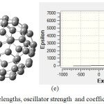 |
Figure 6: Calculated absorption wavelengths, oscillator strength and coefficient absorption of (e) C59Si/C60. |
Figure (6e) belongs to C59Si/C60 which its spectrum shows two absorption peak, one is about 300-600 nm with maximum coefficient absorption 5000 epsilon in 400 nm which can be related to absorption of C59Si and a second one which is about 800-2500nm with maximum coefficient absorption 6500 epsilon in 1265.21 nm. This absorption can be considered as electron transfer from C59Si to C60 which happened in infrared range. Comparing excitation energies of C59Si with C59Si/C60 which are listed in table (6) show us that coupling C59Si with C60 as donor-acceptor not only has made the excitation energies in 300-600 nm with stronger oscillator strength with higher wavelengths but also maximum coefficient absorption has increased from 4500 epsilon in visible range ( for C59Si) to 6500 epsilon in infrared range (for C59Si/C60).
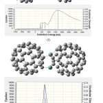 |
Figure 7: Calculated absorption wavelengths, oscillator strength and coefficient absorption of (f) C59Ge/C60 and (g) C58Ge2/C60. |
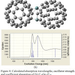 |
Figure 8: Calculated absorption wavelengths, oscillator strength and coefficient absorption of (h) C58Ge2/C60. |
In the next step, C60 is doped once with one Germanium as C59Ge/C60 and also with two Germanium atoms as C58Ge2/C60. The UV/VIS spectrum of C59Ge/C60 (figure 7f) show two absorption peak with maximum coefficient absorptions 5000 epsilon in 720.72 nm and 15000 epsilon in 1687.24 nm, respectively. As for C58Ge2/C60, there is only one absorption peak with maximum coefficient absorptions 9500 epsilon in 500 nm. Also figure (7f) shows a bonding for electron transfer between the doped Germanium atom and one of Carbon atoms in C60 but in figure (7g) one of the two doped Germanium atoms and also one of Carbon atoms of C60 have lost their bonding to create a new ring which happened among two doped Germanium atoms of C58Ge2 and Carbon atoms of C60. This may explain only one absorption peak in the UV-VIS spectrum of C58Ge2/C60.
In C59Ge/C60 spectrum, stronger excitation energies has happened with oscillator Strength 0.0616, 0.0951, 0.1136 and 0.3736 in 400.3 nm, 524.54 nm, 720.72 nm and 1687.24 nm, respectively while in C58Ge2/C60 spectrum, stronger excitation energies with oscillator Strength 0.01272 and 0.0643 are in 506.86 nm and 570 nm which has occurred in visible range. Some of excitation energies and their oscillator Strength of these two donors-acceptors are listed in table (6). These results shows C59Ge/C60 has a good absorption in both visible and infrared range because of doping one Germanium atom but by doping two Germanium atoms not only the structure of donor and acceptor.
Table 6: Absorption wavelengths, oscillator strength of doped C60 derivatives and donors-acceptors compounds.
| Compound | Absorption Wavelengths (nm) | Oscillator Strength |
| C59Si | 297.96 | 0.012 |
| 316.01 | 0.0129 | |
| 342.95 | 0.0229 | |
| 388.21 | 0.007 | |
| 452.3 | 0.1059 | |
| C59Ge | 316.57 | 0.0161 |
| 366.18 | 0.0368 | |
| 418.44 | 0.009 | |
| 452.28 | 0.13 | |
| C58Ge2 | 328.27 | 0.0174 |
| 375.42 | 0.0245 | |
| 445.85 | 0.2319 | |
| C58GeSi | 322.22 | 0.018 |
| 351.49 | 0.0184 | |
| 376.62 | 0.0531 | |
| 393.15 | 0.0298 | |
| 460.96 | 0.0501 | |
| 500.22 | 0.1154 | |
| C59Si/C60 | 342.75 | 0.0195 |
| 375.68 | 0.0283 | |
| 393.8 | 0.0638 | |
| 423.16 | 0.0246 | |
| 445.91 | 0.015 | |
| 539.61 | 0.0124 | |
| 1265.21 | 0.1623 | |
| C59Ge/C60 | 400.3 | 0.0616 |
| 524.54 | 0.0951 | |
| 720.72 | 0.1136 | |
| 1687.24 | 0.3736 | |
| C58Ge2/C60 | 433.23 | 0.0182 |
| 456.57 | 0.0283 | |
| 506.86 | 0.1272 | |
| 570.49 | 0.0643 | |
| 791.74 | 0.0161 | |
| 1185.85 | 0.0106 | |
| C58SiGe/C60 | 432.6 | 0.0164 |
| 445.1 | 0.0344 | |
| 464.57 | 0.1161 | |
| 518.31 | 0.0511 | |
| 530.42 | 0.0118 | |
| 752.36 | 0.187 | |
| 1642.2 | 0.0672 |
Compounds may change but also there will be a decrease in maximum absorption and oscillator Strength UV-VIS spectrum of C58SiGe/C60 (figure 8) shows three absorption peak, the first one is about 300-600 nm with maximum coefficient absorption 8500 epsilon that can be related to absorption of C59Si. In this case excitation energies which has happened in 300-600 nm have stronger oscillator strength than C59Si such as 0.1161 in 464.57 nm (table 6). The increase of excitation energies can be result of doping Germanium atom along side Silicon atom. The second and third peak are about 600-1000nm and 1200- 2000nm with maximum coefficient absorptions 7500 epsilon and 3000 epsilon, respectively. Figure (8) shows, Germanium atom has two bonds with Carbon atoms in C60 while Silicon atom has one bond. As Germanium shows more tendency in being donor than Silicon Atom, we can assume that the second peak is related to electron transfer from Germanium atom to C60 which happened with oscillator strength 0.187 in 752.36nm. Figure (8) also show us a ring between donor and acceptor and it consist of Germanium and Silicon doped atoms and Carbon atom of C60. The electron movements in this ring can result the third absorption peak with oscillator strength 0.0672 in 1642.2nm ( table 6).
Conclusion
C60 is a good acceptor and has no absorption in sunlight range. The theoretical research indicates that by doping C60 with Silicon and Germanium atom, the derivatives will have donor property and can have absorptions in ultraviolet and visible range of sunlight. Furthermore, the results of equations and theoretical UV- VIS spectrums indicates that, when these doped derivatives are used as donor with C60 as their acceptor for basic of a solar cell, the resulted solar cells will have absorption in visible and infrared range of sunlight.
Acknowledgments
The author wishes to thank to the department of chemistry, College of Basic Sciences of Islamic Azad University, Yadegar-e-Imam Khomeini (RAH) Branch for supporting this study specially with computers to perform this research.
References
- Liang, Y.; Xu, Z.; Xia, J.; Tsai, S. T. ; Wu, Y.; Li, G.; Ray, C.; Yu, L. Adv. Mater. 2010, 22, 135-138.
CrossRef - Hoppea, H.; Sariciftci, N. S. Organic. J. Mater. Res. 2004, 19, 1924-1945.
CrossRef - Mishra, A.; Bauerle, P. Angew. Chem. Int. Ed. 2012, 51, 2020-2067.
CrossRef - Fung, D. D. S.; Choy, W. C. H. Organic. Springer-Verlag . 2013, 1, 1-16.
CrossRef - Azazi, A.; Mabrouk, A.; Chemek, M.; Kreher, D.; Alimi, K. Synthetic Metals. 2014,198, 314-322.
CrossRef - Shalabi, A.S.; Abdel Aal, S.; Assem, M.M.; Soliman, K.A. Organic Electronics. 2012,13. 2063-2074.
CrossRef - Beu, T. A.; Onoe, J.; Hida, A. Physical Review B . 2005, 79,155416(1)-155416(5).
- Liu, X.; Huang, C.; Shen, W.; He, R.; Li, M. J. Mol.Model. 2016, 22(15), 1-11.
CrossRef - Koster, L. J. A.; Mihailetchi, V. D.; Xie, H.; Blom, P. W. M. Applied Physics Letters. 2005, 87, 203502(1)-203502(3).
CrossRef - Gupta, D; Mukhopadhyay, S; Narayan, K. Sol Energy Mater Sol Cells. 2010, 94(8), 1309-1313.
CrossRef - Abraha, A.; Gholap, A.V.; Belay, A. International Journal of Biophysics. 2016, 6(2), 16-20.
- Kako, M.; Nagase, S.; Akasaka, T. Molecules. 2017, 22, 1179(1)-1179(17).
CrossRef - Labrunie, A.; Gorenflot, J.; Babics, M.; Alévêque, O.; Dabos-Seignon, S.; Balawi, A.H.; Kan, Z.; Wohlfahrt, M.; Levillain, E.; Hudhomme, P.; Beaujuge, P.M.; Laquai, F.; Cabanetos, C.; Blanchard, P.Chemistry of Materials. 2018,30(10), 3474-3485.
CrossRef - Zheng, Z.; Tummala, N. R.; Fu, Y. T.; Coropceanu, V.; Bredas, J.L. ACS Appl. Mater. Interfaces, 2017, 9 (21), 18095-18102.
CrossRef - Joseph, S.; Ravva, M.K.; Bredas, J.L. J. Phys. Chem. Lett., 2017, 8 (20), 5171-5176.
CrossRef

This work is licensed under a Creative Commons Attribution 4.0 International License.
![]()
A New Edition of Web of Science
Journal Impact Factor
2022: 0.5
Five Year: 0.8
Journal is Indexed in

Cabells Whitelist
![]()


