Numerical Simulation of Drop Formation in Power-Law Fluids
Fahime Hoseinzade and Hamid Reza Ghorbani
Department of Chemical Engineering, Qaemshahr Branch, Islamic Azad University, Qaemshahr, Iran.
Corresponding Author E-mail: hamidghorbani6@gmail.com
DOI : http://dx.doi.org/10.13005/ojc/340663
Article Received on : 29-08-2018
Article Accepted on : 30-10-2018
Article Published : 04 Nov 2018
The purpose of this work was the study of the formation process of Newtonian drop in a continuous non-Newtonian fluid. This process was numerically studied by entering liquid into a submerged orifice in a cylindrical vessel. The simulations were carried out using SOLA-VOF method. In this code, the complete motion equations were predicted two dimensions and using finite difference method. In addition, power law model was used to simulate a non-Newtonian fluid. In this research, the effects of orifice diameter and Newtonian fluid flow rate were studied on the formation of the drop, size and its formation time.
KEYWORDS:Drop Formation; Power Law Model; SOLA-VOF; Two Phase Flow
Download this article as:| Copy the following to cite this article: Hoseinzade F, Ghorbani H. R. Numerical Simulation of Drop Formation in Power-Law Fluids. Orient J Chem 2018;34(6). |
| Copy the following to cite this URL: Hoseinzade F, Ghorbani H. R. Numerical Simulation of Drop Formation in Power-Law Fluids. Orient J Chem 2018;34(6). Available from: http://www.orientjchem.org/?p=52063 |
Introduction
Systems such as droplets and bubbles are an important research topic. The behavior of these systems are depends on the stresses between the two-axial, inertial, surface tension, gravity and pressure gradient between the two fluids, and in the areas of mixing, fermentation, separation, transfer of materials in the chemical industry, oil and gas extraction, cooling, color and printing Used with spray nozzles.1,2 So far, various studies were done using numerical, analytical and laboratory methods for investigating the behavior of multifaceted systems including various fluids. The continuous phase properties have a great influence on the formation and size of the droplet. Many researchers studied the drop formation process and its hydrodynamics.3,4,5 There are several laboratory studies and theory for the formation of drops in a continuous phase. The results are in good agreement with the analytical and numerical results. Itoh et al. (1980) examined the formation of droplets in a parallel or perpendicular to a nozzle and obtained an experimental relationship based on experimental data. They found that the size of the droplet is much smaller for the flow of the nozzle perpendicularly from a parallel flow.6,7,8 Tsug et al. (1983, 1981) studied the effect of the velocity of a horizontal fluid flow in a bubble size and expanded their model to form a bubble in a fluid in order to account for the effect of fluid flow velocity. Over the past decade, it was proved that computational methods are an effective tool for studying the processes in which a multiphase flow takes place. Multiphase flow along the surfaces is a common phenomenon in industrial processes, for example, catalytic processes, phase dispersion, boiling and cavitation, etc. Different methods have been developed to detect fuzzy surface in free-surface flows. They include marker and cell methods, front tracking, Boltzmann’s grid, surface and flow volume sets.9,10,11 In most of the above methods, there are severe disadvantages, such as the need for large amounts of computer memory or long calculation times, making it difficult to apply these methods. However, the fluid volume method was provided by Hirt and Nichls (1981). This method was recently used well to calculate various multiphase flow conditions. Hoffman et al. (2006) and Joe (2004) simulated fluid flow across the slope. Gunjal et al. (2005) simulated the effect of droplets on the solid surface. O’Hatha et al. (2004) simulated the form of droplets in a cavity on a pulsed screen using a fluid volume method. For them, the computational range was two-dimensional and symmetric. Richard et al. (1995) simulated the formation of droplets in liquid-liquid systems before and after fusion conditions.13,14
In this work, we study numerically the drop formation process using the SOLA-VOF in non-Newtonian fluids. The influence of physical parameters as orifice diameter and liquid inlet velocity is studied on the drop diameter and the time of drop formation.
Simulation of Drop Formation
In this work, it was modified SOLA-VOF computational code to use for the process of drop formation in non-Newtonian fluids. In fact, the motion equations were solved with considering the non-Newtonian fluid equations (power law) and also suitable boundary conditions for the drop formation process by the finite-difference method. Finally, it was corrected SOLA-VOF computational code. The following equation was used for the power law model15:
τ = K(γ)n
The drop formation process was simulated in a cylindrical container with an orifice submerged in a non-Newtonian fluid (power law model). This container was with a diameter of 8 cm and a height of 10 cm that it was filled by a non-Newtonian fluid with height of 6 cm. At the end of the container was an orifice with a diameter of 3 mm or 5 mm, which was fed into a constant flow rate of Newtonian fluid.
Results and Discussions
In this study, two cases were investigated. In the first case, hole diameter was about 3 mm and in the second case, it was 5 mm. The superficial velocity in the hole was 1, 5, 10, and 20 cm / s.
Effect of Liquid Flow Rate on Drop Diameter
Tables (1) and (2) show the effect of liquid flow rate on drop diameter. It also was observed the effects of power law model coefficients on the drop diameter. If the effect of surface tension is neglected, the drop diameter is determined by the balance of Buoyancy, inertia and viscous forces for liquids with low viscosity.
Table 1: Drop diameter (mm) for orifice with a diameter of 3 mm.
| K, n | V=1 cm/s | V=5 cm/s | V=10 m/s | V=20 cm/s |
| k=0.171 | 2.94 | 2.99 | 3.02 | 3.03 |
| n=0.0706 | ||||
| k=0.658 | 2.97 | 3.03 | 3.06 | 3.08 |
| n=0.0873 | ||||
| k=0.687 | 2.97 | 3.03 | 3.07 | 3.08 |
| n=0.0113 | ||||
| k=0.937 | 3.03 | 3.13 | 3.18 | 3.19 |
| n=0.2060 | ||||
| k=1.750 | 2.93 | 2.96 | 2.99 | 3.02 |
| n=0.0956 | ||||
| k=0.921 | 3.02 | 3.08 | 3.14 | 3.16 |
| n=0.229 |
Table 2: Drop diameter (mm) for orifice with a diameter of 5 mm.
| K, n | V=1 cm/s | V=5 cm/s | V=10 m/s | V=20 cm/s |
| k=0.171 | 4.92 | 4.97 | 5 | 5.02 |
| n=0.0706 | ||||
| k=0.658 | 4.96 | 5.02 | 5.04 | 5.07 |
| n=0.0873 | ||||
| k=0.687 | 4.95 | 5.02 | 5.05 | 5.07 |
| n=0.0113 | ||||
| k=0.937 | 5.02 | 5.11 | 5.16 | 5.18 |
| n=0.2060 | ||||
| k=1.750 | 4.92 | 4.96 | 4.99 | 5.01 |
| n=0.0956 | ||||
| k=0.921 | 5.01 | 5.08 | 5.13 | 5.15 |
| n=0.229 |
As shown in tables (1) and (2), drop diameter and its volume increase with increasing superficial velocity in the nozzle, and therefore its volume also increases. This increase was observed in diameter of all samples, but there is no suitable relationship between the coefficients k and n with the drop diameter.
Effect Of Liquid flow Rate on the Time of Drop Formation
Tables (3) and (4) show the effect of liquid flow rate on the time of drop formation.
Table 3: Time of drop formation (s) for orifice with a diameter of 3 mm.
| K, n | V=1 cm/s | V=5 cm/s | V=10 m/s | V=20 cm/s |
| k=0.171 | 0.0685 | 0.0602 | 0.0589 | 0.0567 |
| n=0.0706 | ||||
| k=0.658 | 0.0686 | 0.0602 | 0.0588 | 0.0567 |
| n=0.0873 | ||||
| k=0.687 | 0.0686 | 0.0603 | 0.0589 | 0.0567 |
| n=0.0113 | ||||
| k=0.937 | 0.0687 | 0.0604 | 0.059 | 0.0568 |
| n=0.2060 | ||||
| k=1.750 | 0.0685 | 0.0603 | 0.0589 | 0.0567 |
| n=0.0956 | ||||
| k=0.921 | 0.0687 | 0.0604 | 0.059 | 0.0567 |
| n=0.229 |
Table 4: Time of drop formation (s) for orifice with a diameter of 5 mm.
|
K, n |
V=1 cm/s | V=5 cm/s | V=10 m/s |
V=20 cm/s |
| k=0.171 | 0.0811 | 0.0737 | 0.0709 | 0.0688 |
| n=0.0706 | ||||
| k=0.658 | 0.0812 | 0.0738 | 0.0708 | 0.0688 |
| n=0.0873 | ||||
| k=0.687 | 0.0813 | 0.0737 | 0.0709 | 0.0688 |
| n=0.0113 | ||||
| k=0.937 | 0.0813 | 0.0739 | 0.071 | 0.0689 |
| n=0.2060 | ||||
| k=1.750 | 0.0811 | 0.0738 | 0.0709 | 0.0688 |
| n=0.0956 | ||||
| k=0.921 | 0.0813 | 0.0739 | 0.071 | 0.0688 |
| n=0.229 |
As showed in tables (3) and (4), the time of drop formation decreases with increasing liquid velocity in the orifice. The time of drop formation is the time that drop release from orifice. In other words, the time of drop formation decrease with increasing drop volume.
Figure 2 shows the release steps of drop in a non-Newtonian fluid (power law) with orifice diameter 5 mm and liquid velocity 1 cm/s. The time of drop formation decreases with increasing liquid flow rate and release process is more quickly.
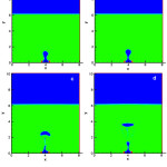 |
Figure 1: The release steps of drop in a non-Newtonian fluid (power law), orifice diameter 5 mm and liquid velocity 1 cm/s. |
Conclusions
In this study, the drop formation process was simulated in a cylindrical container with an orifice submerged in a non-Newtonian fluid (power law model). Simulation was performed using SOLA-VOF numerical model. In this process, two orifices with different diameters were used with different liquid flow rates. Also, it was understood that drop volume increase with increasing liquid flow rate and the time of drop formation decrease with increasing liquid velocity.
References
- Scott, T.; Banks, D.; Mishra, A. Appl Biosaf., 2006, 11(4), 188-196.
CrossRef - Agarwal, A.; Ng, W.; Liu, Y. Chemosphere, 2011, 84 (9), 1175–1180
CrossRef - Park, P.Y.; Tyler, A.L.;Nevers, N. Chem. Eng. Sci., 1997, 32, 907-916.
CrossRef - Valencia, A.; Cordova, M.; Ortega, J. Int. Comm. Heat Mass Transfer, 2002, 29, 821-830.
CrossRef - Treybal, R.E. Mass Transfer Operation, Third Edition, 2003.
- Terasaka, K.;Tsuge, H. Chem. Eng. Sci., 1991, 46, 85-93.
CrossRef - Terasaka, K.;Tsuge, H. Chem. Eng. Sci., 2001,56, 3237-3245.
CrossRef - Yan, K.;Che, D.Int. J.Multiphase Flow, 2011, 37, 299-325.
CrossRef - Chen, Y.; Mertz, R.;Kulenovic, R. Int. J. Multiphase Flow, 2009, 35, 66-77.
CrossRef - Nichols, B.D.; Hirt,C.W.; Hotchkiss,R.S. Los Alamos National Scientific Laboratory, 1980, 119.
- Krishna, R.; van Baten, J.M. Int. Comm. Heat Mass Transfer, 1999, 26, 965-974.
CrossRef - Szewc, K.; Pozorski, J.; Minier,J. P. Int. J. Multiphase Flow, 2013,50, 98-103.
CrossRef - Zhang, W.; Tan, R.B.H. Chem. Eng. Sci., 2000, 55, 6243-6250.
CrossRef - Sarnobat, S. U.; Rajput, S.; Bruns, D.; Depaoli, D.W.; Daw, C.S.; Nguyen, K. Chem. Eng. Sci., 2004, 59, 247-258.
CrossRef - Davison, J.F.; Schuler, B.O.G. Trans.Instn.Chem. Engrs. 1960, 38, 335-342.

This work is licensed under a Creative Commons Attribution 4.0 International License.
![]()
A New Edition of Web of Science
Journal Impact Factor
2022: 0.5
Five Year: 0.8
Journal is Indexed in

Cabells Whitelist
![]()


