Fabrication of Metallic Lines by Aerosol Jet Printing: Study of the Effect of Substrate Temperature on the Aspect Ratio
Alexey Anatolevich Efimov1 , Pavel Vladimirovich Arsenov1, Kirill Nikolaevich Minkov2 and Victor Vladimirovich Ivanov1
1Department of Physical and Quantum Electronics, Moscow Institute of Physics and Technology, Dolgoprudny 141701, Russia.
2Moscow Institute of Electronics and Mathematics, National Research University of Higher School of Economics, Moscow 123458, Russia.
Corresponding Author E-mail: efimov.aa@mipt.ru
DOI : http://dx.doi.org/10.13005/ojc/340613
Article Received on : 20-09-2018
Article Accepted on : 10-11-2018
Article Published : 15 Nov 2018
In this paper we investigated the effect of substrate temperature (25-300 °C) on the aspect ratio (thickness/width) of the silver lines formed by aerosol jet printing (AJP). This effect was studied by varying the speed of substrate (50-250 mm/min) and the number of printing layers (1-25 layers) in order to obtain lines with high aspect ratio. It is shown that AJP on a heated substrate at a temperature equal to >100 °C allows to increase the aspect ratio of the lines more than 17 times in comparison with conventional AJP. It is established that the aspect ratio of the lines increases with the increase in the number of printing layers and the decrease in the speed of substrate. Silver lines with high aspect ratio of 1.7 with a width of about 25 μm were formed. This result is important for the formation of current-carrying microcircuits with a high density of elements.
KEYWORDS:Aerosol Jet Printing; Aspect Ratio; Printed Electronics; Silver Ink
Download this article as:| Copy the following to cite this article: Efimov A. A, Arsenov P. V, Minkov K. N, Ivanov V. V. Fabrication of Metallic Lines by Aerosol Jet Printing: Study of the Effect of Substrate Temperature on the Aspect Ratio. Orient J Chem 2018;34(6). |
| Copy the following to cite this URL: Efimov A. A, Arsenov P. V, Minkov K. N, Ivanov V. V. Fabrication of Metallic Lines by Aerosol Jet Printing: Study of the Effect of Substrate Temperature on the Aspect Ratio. Orient J Chem 2018;34(6). Available from: http://www.orientjchem.org/?p=52604 |
Introduction
The conventional method of aerosol jet printing (AJP) is a universal method for printing electronic components on various substrates using a large selection of functional inks.1–4 The AJP method is becoming more and more popular in the field of printed electronics, as it allows to create inexpensive electronic elements with a size of 10 μm to several millimeters.5–8 Conducting lines with a narrow width and a large cross-sectional area are preferred in printed electronics for the purpose of forming circuits with a high density of elements.6,9 In this regard, the main task of researchers in the field of printed electronics is to create microstructures with high values of the aspect ratio (AR), where the AR is defined as the ratio of thickness to the width of the lines.10 For example, in the paper,6 a technique was investigated to increase the AR of the lines by changing the parameters of the AJP method, namely, by controlling the aerosol and sheath gas flow rates. However, this technique did not significantly allow to increase the AR of the lines to values greater than 0.2. In another paper,11 the AR of the line increased due to the increase in the number of printing layers and the slow printing speed, but this only resulted in a slight increase in the AR of the line, because due to the spreading of the ink, both the thickness and the width of the formed lines increased.
In this paper we investigated the effect of substrate temperature (25-300°C) on the values of AR of the silver lines formed by AJP on a heated substrate. This effect was studied by varying the speed of substrate (50-250 mm/min) and the number of printing layers (1-25 layers) in order to obtain printed lines with high AR.
Experimental
Figure 1 shows the scheme of the experiment setup to study the effect of the substrate temperature on the AR values of silver lines formed by AJP on a heated substrate. The experiments were performed using a commercial aerosol jet printer AJ 15XE (Neotech AMT GmbH).12 The ink used was a conductive silver ink Micro PE PG-007MOP (Paru Co., Ltd) with a mass concentration of silver nanoparticles equal to 50%, dispersed in ethylene glycol.13
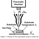 |
Figure 1: Scheme of the experiment setup to study the effect of the substrate temperature on the. |
AR values of silver lines formed by the AJP on the heated substrate, where Qa is the aerosol flow rate, Qsh is the sheath gas flow rate, Vs is the speed of substrate, and Ts is the substrate temperature.
Aerosol particles in the form of liquid microdroplets were obtained by means of a pneumatic atomizer while spraying silver ink. Then the particles were directed to the coaxial nozzle for focusing and deposition on the heated substrate, see Figure 1. In the experiment, a nozzle with an output diameter of 150 μm was used. The distance from the nozzle to the substrate was 2 mm. The aerosol flow rate Qa and the sheath gas flow rate Qsh were 50 and 100 sccm, respectively. Pure nitrogen N2 (99.9999%) was used as the carrier gas for the aerosol and sheath gas flows. The glass substrate was placed on the surface of the C-MAG HP 4 hot plate (IKA Works, Inc.), which moved relative to the nozzle at a variable speed of substrate Vs in the range from 50 to 250 mm/min. During the experiment, the substrate temperature Ts was controlled in the range from 25 to 300°C. The number of printing layers Np varied from 1 to 25 layers. The width and the thickness of the lines for determining the AR of the line were obtained from analysis of the cross-sectional profile of the printed lines, which was measured using an optical profilometer Leica DCM 3D. As a result, a series of experiments were performed to estimate the effect of the substrate temperature on the values of the AR of the lines with a variation in the speed of the substrate and the number of printing layers.
Result and Discussion
Figure 2a shows the dependence of the AR of the silver lines on the substrate temperature in the range from 25 to 300°C with the speed of the substrate equal to 50, 125 and 250 mm/min, where Np=25 layers. As an example, Figure 2b also shows individual cross-section profiles of lines formed on the substrate at Ts=200°C, Np=25 layers and Vs are equal to 50, 125 and 250 mm/min.
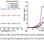 |
Figure 2.a: The dependence of the AR of the silver lines on the substrate temperature in the range from 25 to 300°C at the speed of substrate equal to 50, 125 and 250 mm/min, where Np=25 layers; b). |
The cross-section profiles of the lines formed on the substrate at Ts=200°C, Np=25 layers and Vs are equal to 50, 125 and 250 mm/min.
It can be seen from Fig. 2a that the values of the AR of the silver lines increases linearly with increasing the substrate temperature in the range from 25 to 100°C, and when the substrate temperature increases above 100°C, the AR of the lines did not change and become constant for all values of the speed of substrate. This result indicates that the reason for the growth of the AR of the line in the temperature range from 25 to 100°C is probably associated with a decrease in the degree of spreading of the ink as a result of their rapid drying and solidification on the surface of the heated substrate. As a consequence, the highest values of AR of the line are reached at a substrate temperature equal to or higher than the sintering temperature of the ink. For example, the starting temperature of the sintering used by the silver ink is about 100°C and higher according to the ink specifications.13 In Figure 2a, it is seen in the attainment of AR of the line values for its maximum when the substrate temperature rises above 100°C. In this connection, it can be concluded that in order to form the highest possible microstructures, it is recommended to use the substrate temperature at which the ink dries and solidifies completely during the deposition of the ink on the substrate. Figure 2a shows that the higher AR of the lines are obtained for microstructures formed at a lower speed of substrate, namely at Vs=50 mm/min. However, it should also be taken into account that with a decrease in the speed of substrate from 250 to 50 mm/min, the width of the lines increases from 35±4 to 62±6 μm, respectively, see Fig. 2b. Therefore, in order to obtain at the same time narrow lines having a large cross-sectional area, in subsequent experiments, the Vs was chosen to be 125 mm/min.
Figure 3 shows the dependence of the AR of the lines on the number of printing layers for the heated (Ts=200°C) and unheated (Ts=25°C) substrate at Vs=125 mm/min.
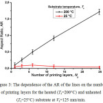 |
Figure 3: The dependence of the AR of the lines on the number of printing layers for the heated (Ts=200°C) and unheated (Ts=25°C) substrate at Vs=125 mm/min. |
Figure 3 shows that when the lines are printed on a heated substrate at Ts=200°C, the AR of the lines increases almost linearly with increasing number of printing layers. For example, the AR of the lines increases from 0.1 to 1.7 when the number of printing layers is increased from 1 to 25 layers, respectively. The use of a heated substrate allows increasing the AR of the line by more than 17 times in comparison with lines printed on an unheated substrate. However, when the lines printing on an unheated substrate at Ts=25°C, the values of AR of the lines remain almost unchanged with increasing number of printing layers. This indicates that when the ink is deposited on an unheated substrate, along with the increase in line thickness due to a larger amount of deposited material, its width also increases proportionally in accordance with the expression AR=(thickness/width). Figure 4 clearly shows the cross-sectional profiles of the lines and their 3D images, depending on the number of printing layers formed at Ts=25°C and Vs=100 mm/min. Figure 4 shows that as the number of printing layers increases, the thickness and width of the lines also increase. This is probably related to the process of spreading ink over the substrate at room temperature.
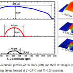 |
Figure 4: The cross-sectional profiles of the lines (left) and their 3D images (right), depending on the number of printing layers formed at Ts=25°C and Vs=125 mm/min. |
Under conditions of printing on a heated substrate, when the material is deposited on the heated surface, the ink dries and solidifies, not having time to spread, and the subsequent layer of the material precipitates already on the sintered surface. Figure 5 also clearly shows the cross-sectional profiles of the lines and their 3D images, depending on the number of printing layers formed at Ts=200°C and Vs=100 mm/min.
It can be seen from Fig. 5 that with an increase in the number of printing layers from 1 to 25 layers, the line width remains almost constant ~25 μm, and the thickness of the line increases from 3 to 40 μm, respectively.
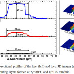 |
Figure 5: The cross-sectional profiles of the lines (left) and their 3D images (right), depending on the number of printing layers formed at Ts=200°C and Vs=125 mm/min. |
Thus, the AJP method on a heated substrate is similar to some of the traditional methods for layered creation of 3D objects.14 According to the results of the experiments, it has been established that using the AJP method on a heated substrate it is possible to form lines with a relatively high aspect ratio AR>1, which is relevant for the creation of electronic circuits with high element densities and is of fundamental importance in the development of new functional 3D micro devices.
Conclusions
The influence of the substrate temperature, the speed of substrate and the number of printing layers on the aspect ratio of the lines formed by the method of aerosol jet printing on the heated substrate is studied. It was found that with an increase in the substrate temperature in the range from 25 to 100°C, an almost linear increase in the values of the aspect ratio of the lines from the substrate temperature is observed. In addition, it was found that the substrate heating temperature above 100°C practically does not affect the AR values for different speed of substrate from 50 to 250 mm/min. The result is probably due to a change in the speed of drying and solidification of the ink on the surface of the heated substrate, which reaches its maximum values and goes to constant at the temperature of complete sintering of the ink on the substrate. It has also been found that the lower the speed of substrate, the more AR of the lines can be obtained. Under the conditions of using the heated substrate to 200°C, by varying the number of printing layers from 1 to 25 layers, the possibility of linear increase in the values of AR of the lines from 0.1 to 1.7, respectively, and having a minimum width of about 25 μm is demonstrated.
Acknowledgements
This work was supported by the grant of the President of Russian Federation for young scientists MK-2302.2017.8 and carried out using the Shared Use Equipment Center for high-precision measuring in photonics (ckp.vniiofi.ru, VNIIOFI). The authors declare no conflict of interest.
References
- Deiner, L. J.; Reitz, T. L. Adv. Eng. Mater. 2017, 19 (7), 1600878.
CrossRef - Ou, C.; Sangle, A. L.; Datta, A.; Jing, Q.; Busolo, T.; Chalklen, T.; Narayan, V.; Kar-Narayan, S. ACS Appl. Mater. Interfaces 2018, 10 (23), 19580–19587.
CrossRef - Kahn, B. E. Org. Print. Electron. 2007, 1 (2), 14–17.
- Eckstein, R.; Rödlmeier, T.; Glaser, T.; Valouch, S.; Mauer, R.; Lemmer, U.; Hernandez Sosa, G. Adv. Electron. Mater. 2015, 1 (8), 1500101.
CrossRef - Rahman, T.; Renaud, L.; Heo, D.; Renn, M.; Panat, R. J. Micromechanics Microengineering 2015, 25 (10), 107002.
CrossRef - Mahajan, A.; Frisbie, C. D.; Francis, L. F. ACS Appl. Mater. Interfaces 2013, 5 (11), 4856–4864.
CrossRef - Laurent, P.; Stoukatch, S.; Dupont, F.; Kraft, M. Microelectron. Eng. 2018, 197, 67–75.
CrossRef - Efimov, A.; Potapov, G.; Nisan, A.; Urazov, M.; Ivanov, V. Orient. J. Chem. 2017, 33 (2), 1047–1050.
CrossRef - Suherman; Hossain, M. M.; Morita, K.; Kawaguchi, T. Orient. J. Chem. 2018, 34 (3), 1355–1361.
- Suganuma, K. Introduction to Printed Electronics; SpringerBriefs in Electrical and Computer Engineering; Springer-Verlag: New York, 2014.
- Kopola, P.; Zimmermann, B.; Filipovic, A.; Schleiermacher, H.-F.; Greulich, J.; Rousu, S.; Hast, J.; Myllylä, R.; Würfel, U. Sol. Energy Mater. Sol. Cells 2012, 107, 252–258.
CrossRef - Neotech AMT – 3D Printed Electronics http://www.neotech-amt.com/ (accessed Sep 17, 2018).
- http://paru.co.kr/ko-KR/Web/Print/Product/Ink/ (accessed Sep 13, 2018).
- Ligon, S. C.; Liska, R.; Stampfl, J.; Gurr, M.; Mülhaupt, R. Chem. Rev. 2017, 117 (15), 10212–10290.
CrossRef

This work is licensed under a Creative Commons Attribution 4.0 International License.
![]()
A New Edition of Web of Science
Journal Impact Factor
2022: 0.5
Five Year: 0.8
Journal is Indexed in

Cabells Whitelist
![]()


