Zeolite-Templated NiO Nanostructure for Methanol Oxidation Reaction
Daifallah M. Aldhayan
Department of Chemistry, Faculty of Science, King Saud University, Riyadh, Kingdom of Saudi Arabia.
Corresponding Author E-mail: aldhayan@ksu.edu.sa
DOI : http://dx.doi.org/10.13005/ojc/340549
Article Received on : 23-08-2018
Article Accepted on : 10-09-2018
Article Published : 16 Oct 2018
NiO nano particles with particle size of 10.0 to 15.0 nm using zeolite as a template were successfully prepared and loaded (NiO 10 wt.%) on functionalized carbon nanofibers (CNFs). The as-prepared material NiO-CNFs was characterized and tested as an electrocatalyst and a catalyst for the methanol conversion. Electrocatalytic results showed high stability which was evinced by repetitive cycles as a result of catalyst surface activation. Gas phase catalytic tests were carried out at 290oC over NiO-CNFs catalyst in fresh, reduced, and oxidized forms. The results showed that dimethyl ether (DME) and CO2 were obtained as main products. Formaldehyde (FA), methyl formate (MF) and dimethoxymethane (DMM) were obtained as traces. The conversion of methanol in the absence of H2 or O2 over inactivated NiO-CNFs catalyst suggested that DME reacts with the formed H2O to produce CO2. In both cases, reactivation of the catalyst by H2 (reduction) or by Air (oxidation), the conversion was increased indicating a regeneration of the catalyst.
KEYWORDS:Electrocatalyst; Fuel Cell; Methanol Oxidation; Microporous; NiO Nanoparticles; Template; Zeolite
Download this article as:| Copy the following to cite this article: Aldhayan D. M. Zeolite-Templated NiO Nanostructure for Methanol Oxidation Reaction. Orient J Chem 2018;34(5). |
| Copy the following to cite this URL: Aldhayan D. M. Zeolite-Templated NiO Nanostructure for Methanol Oxidation Reaction. Orient J Chem 2018;34(5). Available from: http://www.orientjchem.org/?p=50859 |
Introduction
Porous solids are categorized in three classes: Microporous materials with a pore diameter (< 2nm), mesoporous materials are materials with a pore diameter of 2-50 nm and macroporous materials with a pore diameter (> 50nm).1,2 Mesoporous materials have attracted high interest due to their unique properties such as large surface area, uniform pore size and pore size distribution which makes them suitable for many applications such as energy conversion,3 Sensors,4 Catalysis5 and bio-related applications.6 They are also used as templates for making molecular sieves, sensors and synthesis of controlled size nanoparticles.2 On the other hand, microporous materials such as zeolite are known for many applications such as catalysis, and sorption due to their high stability and selectivity.7 It has been reported that zeolite can be used as a starting materials to produce mesoporous structures through desiccation process by alkaline treatment of zeolite.7.8 Here we report the syntheses of Nickel oxide nanoparticles using zeolite ZSM-5 to produce mesoporous structure and then the removal of the zeolite by the alkali treatment. Prepared NiO Nanoparticles has been supported on carbon fibers to be used as electrocatalyst and a catalyst towards methanol conversion.
Materials and Methods
Zeolite Preparation and Loading
In a typical hydrothermal synthesis procedure,9 an exact amount of 3.4M NaOH solution was added to Pyramid sodium silicate (29.25% wt SiO2, 8.85% wt Na2O, 61.9% wt H2O) (Crossfield Chemicals) under stirring at room temperature, then a mixture solutions of sodium Aluminate NaAlO2 (52.3% wt Al2O3, 47.7% wt Na2O) (BDH Chemicals) and Tetra Propyl Ammonium Hydroxide TPAOH (20% aqueous solution) (Aldrich Chemicals Co) were added individually with vigorous stirring. The reaction kept under stirring for at least 2 hours and then transferred into a 250 ml Teflon-lined steel autoclave. Reaction kept at 170°C under pressure for 24 h. The product was filtered, rinsed with deionized water, dried, and calcined at 540°C for 8 hours to remove the template.10 A certain amount of the prepared ZSM-5 zeolites was then kept under vacuum at 150°C overnight, then added to a solution of Ni(NO3)2 and sonication for 4 h., followed by vacuum drying. Zeolite sample loaded with Nickel salt was then calcined at 350°C for 2 hours. Zeolite template was removed using 1M NaOH solution for 5 hours at 80°C with stirring.
Preparation of NiO/Carbon Fiber Nanocatalyst
Carbon fibers support was prepared according to the method reported by Al-Enizi et. al.11. In a typical synthesis, polyacrylonitril elctrospin fibers were produced using electrospinning technique. Produced fibers were collected, dried then transferred to carbon fibers using pyrolysis process under Nitrogen atmosphere at 1100 ○C for 6 h. The obtained NiO material was dried at 70°C overnight. To achieve 10 wt.% loading of NiO on the Carbon fibers (CNFs), an appropriate amount of NiO and CNFs was mixed and sonicated in deionized water for 30 min.
Materials Characterization
The C, H, and N contents of prepared NiO/Carbon fiber nanocatalyst were determined using PerkinElmer 2400 Series II CHNS/O elemental analyzer and for the characterization of crystal structure, Bruker D8 Advance x-ray diffractometer has been used. The TEM characterization of NiO nanoparticles was preform on Jeol high resolution transition electron microscope (HRTEM 2100) operated at 200kV.
Catalytic Measurements
Conversion of methanol was used to test the acid and redox properties of the catalyst. Oxidation tests were carried out at atmospheric pressure using a fixed-bed continuous- flow reactor. The catalyst (250 mg), packed in a stainless steel reactor, was preconditioned at 330oC under air flow for 2 h at a rate of 80 ml/min. After the pre-treatment, the reagent mixture, which consisted of a mixture of methanol and air with volume ratio air/CH3OH = 2/0.5, was admitted in the reactor (admission of methanol was carried out automatically and continuously by micro-injection through a syringe). The reaction was conducted at 250oC. AS for reduction tests, the loaded catalyst sample was preconditioned at 330oC under H2 flow for 2 h at a rate of 80 ml/min. After the pre-treatment, the reagent mixture, methanol and H2 (H2/CH3OH = 2/0.5), was admitted in the reactor.
The reaction products were analyzed with a gas phase chromatograph (Agilent 6890N) equipped with a flame ionization detector and a capillary column (HP-PLOT Q length 30m ID 0.53 mm).
Electrocatalytic Measurements
Working electrodes were fabricated by dispersing 0.2 mg of the prepared materials in a solution of 0.5 ml isopropyl alcohol and 0.1 ml Nafion (10 wt.%) and sonicating the solution for 1 h. Next, 10 μl of the dispersion was cast onto a glassy carbon (GC) disk electrode (GAMRY Instrument Company, A = 0.071 cm2) and left to dry overnight. Before inserting the electrode into the electrolytic cell, its surface was flushed with the same electrolyte that was used in the measurements in order to confirm the surface wettability.11
Results and Discussion
The result of X-ray powder diffraction analysis of the calcined ZSM-5 zeolite is shown in Fig. 1. The sample exhibited the characteristic diffraction lines of the ZSM-5 framework characterized by the reflections in the 2theta range of 7−9°C and 23−25°C, which matched well with the standard pattern of ZSM-5 zeolite.12 The obtained XRD spectrum confirmed successful preparation of a highly crystalline ZSM‐5, as indicated by the well resolved XRD peaks and the weak background noise in the XRD patterns.
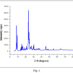 |
Figure 1: XRD patterns of the ZSM-5 calcined at 540°C for 8 hours. |
TEM image after alkali treatment of zeolite template (Fig. 2), indicate the formations of uniform NiO particles of thickness about 3-6 nm.
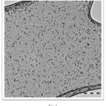 |
Figure 2: TEM images of NiO nanoparticles. |
The XRD pattern of the prepared NiO/CNFs electrocatalyst shows diffraction peaks at 2θ 37.3°C, 43.3°, indexed to the (111) and (200) of cubic NiO phases respectively (Fig. 3),13 and a diffraction peak at about 26°C which can be assigned to plane (002) of the hexagonal structure of the carbon nanofibers CNFs.10 The other smaller XRD peaks at about 2θ 52°C and 77°C are assigned to (004) and (110) planes of the hexagonal structure of Graphite C 2H (ICDD 00-041-1487) respectively.
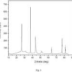 |
Figure 3: XRD patterns of CNFs loaded with 10%NiO. |
The prepared electrocatalyst with composition of 10%NiO/CNFs has been tested for the methanol oxidation reaction. The electrocatalytic activity has been recorded in Fig. 4, indicating the presence of methanol oxidation peak in the potential range between +1.1 to +1.3 V. On the other hand, Fig. 5 shows the effect of the scan rate on the peak current, indicating the increase of the peak current with increasing the scan rate. Stability proof of the Prepared electrocatalayst, can be assured by repetitive cycling between +0.5 V and + 1.5 V in 0.5 M KOH + 1 M MeOH solution at temperature of 25°C and a scan rate of 50 mV s-1, results were depicted in Fig. 6. Figure 6 shows that, the peak current density increased from 0.95 mA cm-2 in the 1st cycle to 1.2 mA cm-2 in the 20th cycle as a result of catalyst surface activation by repetitive cycling. However, after NaOH treatment of the zeolite, the formation of nickel silicate cannot be excluded. This can be in partial, the reason for the high stability of the catalyst. Additional studies of both the intermediate NiO material and the final NiO-CNFs catalyst are needed.
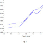 |
Figure 4: CV 10%NiO/CNF in a solution of 0.5 M KOH/1M MeOH at a scan rate of 50 mVs-1. |
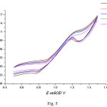 |
Figure 5: CV for the 10%NiO/CNF in a solution of 0.5 M KOH/1M MeOH at different scan rate. |
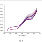 |
Figure 6: Repetitive CVs for 10% NiO/CNFs in a solution of 0.5M M KOH + 1 M MeOH at 25oC at a scan rate of 50 mV s-1. |
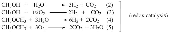
The reaction of methanol conversion is considered to be sensitive to the structure,14 the dispersion15 and the interaction force between the active phase and the support.16 For this reason it was selected as a reaction test to characterize the as-prepared catalyst. The reactions of conversion of methanol were carried out at 290oC and 250oC over the as-prepared catalyst. The results show that the reaction led to dimethyl ether (DME) and CO2 as main products while formaldehyde (FA), methyl formate (MF) and dimethoxymethane (DMM) were observed as traces.
DME can be produced by methanol dehydration:
CH3OH → CH3OCH3 + H2O (1)
acid catalysis
CO2 can be produced by methanol or by DME total oxidation.
The acid character of the catalyst is indicated by the amount of dimethyl ether (DME) formed, while the redox character is indicated by the formation of CO2. Besides CO2, the other reaction products such as FA, (FM) and DMM, which are formed by condensation of methanol and FA in consecutive reactions, also indicate the redox character of the catalyst.
The catalyst was tested initially, for the conversion of methanol at a reaction temperature of 290°C without being activated. The results (Fig. 7) showed that the conversion increased as the reaction time increased from 0.5 to 2 hours. Beyond 2h, it decreased, indicating the deactivation of the catalyst. As for the variation of the selectivities with time on stream, it has been found that when the reaction time increases from 0,5 to 2h, the selectivity of the DME decreased in favor of CO2. The formation of the DME is due to the acidic sites (OH) created during the functionalization (treatment with H2SO4) of the CNFs support. In fact, the treatment with H2SO4 leads to the creation of oxygenated groups (Acid sites and redox) such as COOH, C=O and OH. Then, the DME form is oxidized by the redox sites of the support and NiO leading to the formation of CO2. These results are in agreement with those reported in the literature17 where it was mentioned that methanol leads to DME which reacts with H2O to produce CO2 (CH3OCH3 + 3H2O → 6H2 + 2CO2).18 CO2 is also formed by reactions of methanol with H2O19
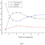 |
Figure 7: Dependence of the conversion and product selectivities on time on stream reaction over NiO/CNFs, at 290oC. |
The sample that was tested for the reaction of methanol alone at 290oC was activated by H2 and tested for the CH3OH/H2 reaction, then after it was activated by air, it was tested for the CH3OH/Air reaction at the same reaction temperature. The change of the conversion and the selectivities with time on stream are shown in Figs. 8 and 9 respectively. It can be seen that in both cases the conversion increased with temperature and reached a value higher than that obtained for the reaction of methanol alone. As for the selectivities, it can be seen that H2 increased the selectivity of DME to the detriment of that of CO2, whereas air (O2) decreased DME selectivity in favor of that of CO2. These results can be explained by the fact that H2 shifts the equilibrium of the conversion of DME to the left (equation 4) and thus decreased the conversion of DME into CO2. On the other hand, O2 increased the conversion of methanol and DME to CO2.
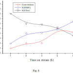 |
Figure 8: Dependence of the conversion and product selectivities on time on stream reaction over NiO/CNFs. |
Reaction conditions: reaction temperature 290oC; activation temperature 330oC for 2 h under H2; volume ratio H2/CH3OH =2/0.5.
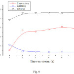 |
Figure 9: Dependence of the conversion and product selectivities on time on stream reaction over NiO/CNFs. |
Reaction conditions: reaction temperature 290oC; activation temperature 330oC under Air for 2 h; volume ratio Air/CH3OH = 2/0.5.
In order to see the effect of temperature on the CH3OH/O2 reaction, the catalyst sample was activated at 330°C and then tested at 250°C. The results (Fig. 10) show a slight decrease in the conversion, which indicates a slight deactivation of the catalyst. On the other hand, a slight decrease in the selectivity of the DME in favor of FM and DMM was observed while the selectivity of CO2 remained almost unchanged. These results are in agreement with those reported in the literature20, 21 where it has been reported that DMM and MF can be formed from DME. Compared to the results obtained at 290oC, it can be concluded that MF, DMM which are formed from CH3OH or via DME, are converted to CO2 by total oxidation. Taking into account the obtained results, the possible reaction routes of CO2, DME, MF and DMM can be found in scheme 1.
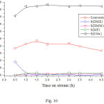 |
Figure 10: Dependence of the conversion and product selectivities on time on stream reaction over NiO/CNFs. |
Reaction conditions: reaction temperature 250oC; activation temperature 330oC under Air for 2 h; volume ratio Air/CH3OH = 2/0.5.
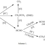 |
Scheme 1: Proposed methanol reactions pathways on 10%NiO/CNF catalyst. |
Conclusion
NiO nano particles were succefully prepared and loaded on functionalized carbon nanofibers (CNFs). The as-prepared NiO-CNFs material was tested as electrocatalyst and catalyst for the conversion of methanol in gas phase. The results show that the NiO/CNFs catalyst has considerable activities for methanol oxidation. In fact it showed high stability which proofed by repetitive cycles as a result of catalyst surface activation. However, additional studies of both the intermediate NiO material and the final NiO-CNFs catalyst are recommended for future work.The conversion of methanol in gas phase at 290oC over NiO-CNFs catalyst in fresh, reduced, and oxidized forms, led to dimethyl ether (DME) and CO2 as main products. Formaldehyde (FA), methyl formate (MF) and dimethoxymethane (DMM) were observed as traces.
The conversion of methanol alone at 290oC over fresh (neither reduced nor oxidized) NiO-CNFs catalyst showed a decrease of the selectivity of DME in favor of that of CO2 which suggest that DME reacts with the formed H2O to produce CO2.
Reactivation of the catalyst by H2 (reduction) increased the selectivity of DME to the detriment of that of CO2 (partial oxidation), whereas reactivation by air (oxidation) decreased DME selectivity in favor of that of CO2 (total oxidation). Both cases of reactivation increased the conversion of methanol.
Results of methanol conversion at lower reaction temperature (250oC) showed a decrease of DME selectivity in favor of that of FM and DMM which indicated that DMM and MF can be formed via DME at lower temperature.
Acknowledgments
This project was supported by King Saud University, Deanship of Scientific Research, College of Science Research Center.
References
- Jansen, J. C.; Stocker, M.; Karge, H. G.; Weitkamp, J. In: Stöcker, M.; Karge, H. G.; Jansen, J. C.; Weitkamp, J. (Eds.). Advanced Zeolite Sience and Applications-Studies in surface science and catalysis, Elsevier Science B.V., 1994, 85.
- Xu, Q. Nanoporous Materials-Synthesis and Applications, CRC Press, Taylor&Francis Group, 2013.
- Liu, Y.; Che, R.; Chen, G.; Fan, J.; Sun, Z.; Wu, Z.; Wang, M.; Li, B.; Wei, J.; Wei, Y.; Wang, G.; Guan, G.; Elzatahry, A. A.; Bagabas, A. A.; Al-Enizi, A. M.; Deng, Y.; Peng, H.; Zhao. D. Sci Adv., 2015, 1(4), e1500166.
CrossRef - Li, Y.; Luo, W.; Qin, N.; Dong, J.; Wei, J.; Li, W.; Feng, S.; Chen, J.; Xu, J.; Elzatahry, A. A.; Es‐Saheb, M. H.; Deng, Y.; Zhao. D. Angew. Chem. Int. Ed., 2014, 53, 9035-9040.
CrossRef - Zhang, R.; Shen, D.; Xu, M.; Feng, D.; Li, W.; Zheng, G.; Che, R.; Elzatahry, A. A.; Zhao, D. Adv. Ener. Mater., 2014, 4(8), 1 – 7.
CrossRef - Elzatahry, A. A.; Salah El-Din, T. A.; Elsayed, A.; Aldhayan, D. M.; Wadaan, M. A. M.; Al-Enizi, A. M.; Al-Deyab, S. S. Sci. Adv. Mater., 2014, 6 (7) 1531-1534.
CrossRef - Stevens, W. J. J.; Meynen, V.; Bruijn, E.; Lebedev, O. I.; Van Tendeloo, G.; Cool, P.; Vansant, E. F. Microporous Mesoporous Mater. 2008,110 (1), 77–85.
CrossRef - Groen, J. C. ; Moulijn, J. A. ; Perez-Ramirez, J. J. Mater. Chem. 2006, 16 (22), 2121-2131.
CrossRef - Salah El-Din, T. A.; Elzatahry, A. A; Aldhayan, D. M.; Al-Enizi, A. M.; Al-Deyab, S. S. Int. J. Electrochem. Sci., 2011, 6, 6177-6183.
- Al-Enizi, A. M.; Ghanem, M.A.; El-Zatahry, A. A.; Al-Deyab, S. S. Electrochim. Acta. 2014, 137, 774–780.
CrossRef - Al-Enizi, A. M.; Elzatahry, A. A.; Abdullah, A. M.; AlMaadeed, M. A.; Wang, J.; Zhao, D.; Al-Deyab, S. S. Carbon, 2014, 71, 276-283.
CrossRef - Treacy, M.M.; Higgins, J.B. Collection of Simulated XRD Powder Patterns for Zeolites, fifth revised ed., Elsevier, 2007.
- Elzatahry, A. A. Int. J. Electrochem. Sci., 2014, 9, 22-31.
- Tatibouet, J. M. ; Germain, J. E. ; Volta, J. E. J. Catal., 1983, 82 (1), 240-244.
CrossRef - Louis, C.; Tatibouet, J. M. ; Che, M. J. Catal., 1988, 109 (2), 354-366.
CrossRef - Roozeboom, F.; Cordingley, P. D.; Gellings, P. J. J. Catal., 1981, 68 (2), 464-472.
CrossRef - Wang, X.; Ma, K.; Guo, L.; Tian, Y.; Cheng, Q.; Bai, X. Appl. Catal. A, General, 2017, 540, 37–46.
CrossRef - Kim, D.; Park, G.; Choi, B.; Kim, Y-B. Int. J. Hyd. Ener. 2017, 42 (49), 29210-29221.
CrossRef - Navarro, R. M.; Peña, M. A.; Fierro, J. L. G. J. Catal., 2002, 212 (1), 112–118.
CrossRef - Zhang, Q. ; Tan, Y. ; Yang, C. ; Han, Y. Catal. Commun., 2008, 9(9), 1916–1919.
CrossRef - Liu, G.; Zhang, Q.; Han, Y.; Tsubaki, N.; Tan, Y. Green Chem., 2013, 15, 1501-1504.
CrossRef

This work is licensed under a Creative Commons Attribution 4.0 International License.
![]()
A New Edition of Web of Science
Journal Impact Factor
2022: 0.5
Five Year: 0.8
Journal is Indexed in

Cabells Whitelist
![]()


