Effects of Dopant Ions on the Properties of Polyaniline Conducting Polymer
Hasan Fisal Alesary1 , Hani Khalil Ismail2, Ahmed Fadhil Khudhair1 and Mohammed Qasim Mohammed3
1Department of Chemistry, College of Science, University of Kerbala, Karbala, Iraq.
2Department of Chemistry, Faculty of Science and Health, Koya University, Koya, Kurdistan Region Iraq.
3Department of Chemistry, College of education for pure sciences, University of Basrah, Basrah, Iraq.
Corresponding Author E-mail: hasan.f@uokerbala.edu.iq
DOI : http://dx.doi.org/10.13005/ojc/340539
Article Received on : 15-08-2018
Article Accepted on : 10-10-2018
Article Published : 18 Oct 2018
This work will show, for the first time, the effect of nicotinic acid (NA) and 2-methylnicotinic acid (MNA)on the synthesis and properties of conducting polyaniline (PANI). The work investigates the effects of sulphuric acid (H2SO4), nicotinic acid (NA), and 2-methylnicotinic acid (MNA) on the synthesis and properties of polyaniline. The results show that the preparation of polyaniline from a sulphuric acid electrolyte is faster than the preparation from nicotinic acid and 2- methylnicotinic acid electrolytes. Moreover, the electrical conductivity and thermal stability of PANI/H2SO4 were greater than PANI/NA and PANI/MNA. All the polymers prepared in this study were identified using FT-IR. Scanning electron microscopy (SEM) was used to examine the morphologies of the PANI samples, from which it was determined that PANI/H2SO4 has a fibrous and open structure with a higher porosity morphology compared to PANI/NA and PANI/MNA. The electrical conductivities of the PANI samples were measured as 1.09 S cm-1, 0.65 S cm-1 and 0.089 S cm-1 for PANI/H2SO4, PANI/NA and PANI/MNA, respectively. The thermal stability of PANI was examined using the Thermogravimetric Analysis (TGA) technique. PANI/H2SO4 was found to degrade between 450-500°C, while PANI/NA and PANI/MNA decomposed at temperatures between 300-400°C.
KEYWORDS:Conductivity And Thermal Stability; Dopants (Acids); Polyaniline (PANI)
Download this article as:| Copy the following to cite this article: Alesary H. F, Ismail H. K, Khudhair A. F, Mohammed M. Q. Effects of Dopant Ions on the Properties of Polyaniline Conducting Polymer. Orient J Chem 2018;34(5). |
| Copy the following to cite this URL: Alesary H. F, Ismail H. K, Khudhair A. F, Mohammed M. Q. Effects of Dopant Ions on the Properties of Polyaniline Conducting Polymer. Orient J Chem 2018;34(5). Available from: http://www.orientjchem.org/?p=51092 |
Introduction
Previous studies have demonstrated that polyaniline (PANI) has electrical properties,1-5 and therefore it can be classified as a conducting polymer. Recently, conducting PANI has received considerable attention and has been the subject of intense study due to its interesting properties, low cost, chemical stability and its potential applications in electronics, electromechanical applications and sensors.6-9 PANI is widely used in composites in battery electrodes, 8,10,11 and has been used in supercapacitors and microwave absorption systems.12,13 The type and amount of dopant present during the polymerisation process plays a significant role in determining the conductivity of the resultant polyaniline.13 The presence of nitrogen atoms in the backbone of the structure can significantly affect the properties of the PANI since there is no continuous carbon-carbon chain. The primary sites in the backbone chain of PANI are inhibited by the nitrogen atoms. 14 Therefore, this heteroatom shows that PANI has a much more complex structure and properties than most other conductive polymers.
PANI can be synthesized by chemical or electrochemical methods. In either method the conjugated monomer is polymerised and charge carriers are created through using certain dopants. 15 Here, the presence of the dopant is very important, where the charge carriers and conductivity of the polymer can be affected by the degree and type of dopant. Two types of redox doping can be used in the process of producing a conducting polyaniline polymer: the first is n-type doping (reduction) and the second p-type doping (oxidation).15-17 A radical cation forms during the polymerisation process through the removal of an electron from a monomer structure. Any radicals so produced will link to form a chain of monomers. A simple reaction demonstrating chemical polymerisation is shown in Equ. 1

The influence of dopants on the synthesis and properties of PANI.
PANI is widely used in various industrial fields due to its attractive properties compared to other conducting polymers such as polyacetylene (PA) 18-22 polypyrrole (PPy) 23 and polythiophene (PT) 24. Researchers are interested in improving properties such as the electrical conductivity, stability and processability of PANI through the choice of appropriate dopants. Furthermore, the properties of conducting polymers can be modified depending on the type of monomer; researchers have been successful in the preparation of PANI possessing highly desirable properties by blending it with polymers that have excellent physical and mechanical properties.16,25 The influence of dopants on the synthesis and properties of PANI have previously been studied; however, to the best of our knowledge, the effects of nicotinic acid (NA) and 2-methylnicotinic acid on the synthesis and properties of conducting polyaniline have not previously been considered. Researchers are currently interested in the production of polymers with high electrical conductivity without the need for fillers. This work focuses on the investigation of the influence of dopants on the properties of PANI. The dopants used are sulphuric acid, H2SO4, nicotinic acid (NA) and 2-methylnicotinic acid (MNA). As noted earlier, the objective of this study was to improve the properties of PANI, though it was also interesting to synthesise PANI using non-hazardous, safe and economic dopants. Normally hydrochloric acid, HCl, sulphuric acid, H2SO4, and chloric acid, HClO3, are used as dopants in the synthesis of conducting polyaniline. However, these materials are hazardous. Nicotinic acid (NA) and 2-methylnicotinic acid are not hazardous and can be considered as ‘green’ materials; also, neither of these materials is expensive. 26-28 Consequently, in this work nicotinic acid (NA) and 2-methylnicotinic acid have been used to negate the need to use hazardous compounds in the preparation of the PANI. The results have been compared to the preparation of PANI from a sulphuric acid solution.
Materials and Methods
Aniline (Sigma – Aldrich, 99%), was used as received. Ammonium persulfate (APS) (Sigma – Aldrich, 98%) was used as an oxidation agent, while sulphuric acid (Fisher Chemical, > 95%), nicotinic acid (NA), (Sigma, ≥ 99.5%) and 2-methylnicotinic acid (MNA) (Sigma – Aldrich, ≥98.0%) were used as received with their respective purities.
Procedure
PANI was prepared separately by dissolving 5 ml of aniline in 81.5 ml of 1 M of sulphuric acid, nicotinic acid or 2-methylnicotinic acid and mixed for 30 minutes with stirring with an ice bath. 9.32 g of ammonium persulfate (APS) was dissolved in 50 ml of 1 M acid electrolyte. The solution of APS was added dropwise to a solution of aniline (10 drops per minute) in order to prevent the reaction increasing the temperature of the solution. The colour started to change to blue after 15-20 mins of adding the oxidant, after which it gradually turned increasingly green. The process was performed at 0-1°C, controlled using an ice bath, magnetic stirring and a thermometer, as shown in the Fig. 1. Polymerisation took 4 hours, at the end of which a significant volume of PANI had been formed. A Buchner funnel was used to filter the product, and about 500 ml of 1 M H2SO4 was used to wash the final product before a further, final wash with 1 L of distilled water. The product was subsequently dried at 40°C for 24 hours. Under the same conditions, PANI/NA and PANI/MNA was synthesised, which was achieved by adding 50 ml of ammonium persulfate solution to 1 M nicotinic acid or 2-methylnicotinic acid electrolyte containing aniline. PANI was formed, and then filtered, washed with distilled water and dried at 40°C.
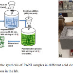 |
Figure 1: a) Schematic of the synthesis of PANI samples in different acid electrolytes. Panel b) picture of the polymerisation process in the lab. Click here to View figure |
Aniline polymerisation is illustrated in Fig. 2
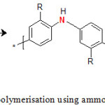 |
Figure 2: Simple reaction for aniline polymerisation using ammonium persulfate at 0-1oC. Click here to View figure |
The spectra of PANI samples were recorded using a Perkin Elmer Spectrum One Fourier Transform Infrared spectrophotometer (FT-IR). The polymer spectra were recorded over the range 650-4000 cm-1 and the data was transformed to Microsoft Excel files using the Spectrum 3.01 software and then analysed using the Origin Pro 8 graphing program. Scanning electron microscope (SEM) images were obtained using a JEOL-63 10 instrument with an accelerator voltage of 15 keV and was controlled by the ISIS 200 software. Conductivity values for polymer samples were recorded using the van der Pauw four-probe method. Dry polymer powder was pressed into discs by using a standard 13 mm disc compressor (30 ton press, C-300 Research and Industrial Instruments Company, London, England). Then, the sample discs were put in a PTFE cell to make four-probe measurements using uniformly spaced, spring-loaded, silver-coated copper electrodes at the periphery. The thickness of polymer samples was measured by means of a digital micrometre. A Keithley 195 current source and a Keithley 197 electrometer were employed to measure the electrical controlled by computer. The conductivity of polymers was calculated using the van der Pauw equation, as follows:
![]()
where σ is the polymer conductivity, R is the gradient of the voltage vs. current graph and d is the thickness of the disc. The thermal stabilities of the PANI samples prepared in this work were investigated using the TGA method. Powders of each PANI sample were placed in a platinum crucible and then on a Mettler Toledo M3 balance. The displacement of the balance beam was monitored with a pair of photodiodes. The Mettler Graphware TA72PS2 software package was used to process the raw data. The data were transferred from Qnix to MS-DOS, and re-plotted using Origin Pro 8.
Results and Discussion
As mentioned above, different methods can be used to synthesise polyaniline. Various previous studies have attempted to interpret the polymerisation mechanism of polyaniline 16,29-33 ; first, the aniline reacts with the acid to form the anilinium cation; in this step protons react with the nitrogen atoms in aniline. The second step is the addition of the oxidant to the aniline, where an electron will be removed from the aniline structure, or from anilinium cation aniline, followed by the immediate removal of the proton. This step is particularly important in the process of polyaniline synthesis because it represents the beginning of the formation of the anilinium radical cation, which is considered a key species in the polymerisation process. The proton emitted as a result of removing the electron from the aniline results in the production of the anilinium radical cation from which dimers can be formed, as shown in Fig. 3.
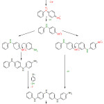 |
Figure 3: Mechanism of polyaniline formation.15,16 Click here to View figure |
A number of dimers will be formed when additional APS is added to the aniline solution. The interaction between the dimers will result in the formation of a long-chain polymer at the end of the polymerisation process. Previous studies have shown that the polymerisation of polyaniline is more likely to occur at the N- and para site of the aniline that the coupling of dimers (i.e., head to tail coupling) as shown in Fig. 3, because ortho coupling is unlikely due to steric effects. 34-37
FT-IR Spectroscopy of Polyaniline
It is vital to understand the PANI structures obtained from different acid electrolytes. In this work, FT-IR was used to determine the various structures of the PANI.34, 38 Fig. 4 shows the FT-IR spectra of PANI obtained from 1 M of H2SO4, NA and MNA solutions. A clear peak at about 3438 cm-1 is apparent for all PANI samples, which arises from the N-H stretching of aromatic amines.39 The C-H stretch of the aromatic ring can be assigned to the range between 2996 and 2922 cm-1. This peak has been shown to shift lower to 2922 cm-1 and appeared as a wide peak, and in the case of the PANI polymerised in the presence of MNA the peak may overlap with the O–H stretching mode of the dopant (MNA), suggesting that the MNA groups are successfully incorporated into the PANI. The peak at 1556 cm-1 is indicative of the quinoid rings, while the peak at 1477 cm-1 relates to the C=C stretch of benzene. The C=C stretching become slightly stronger in the PANI produced from the MNA electrolyte. This could be due to presence of dopant (MNA) in the PANI backbones.16, 32, 39 The C=N stretch has a peak at 1305 cm-1.40 The peaks at about 1120 to 1130 cm-1 corresponded to the C-H out-of-plane (o/p) bending vibration,41 while the peak observed at 798- 802 cm-1 is associated with meta-substituted rings. It is clear in Fig. 4 that most of the spectra of PANI obtained from MNA solution contain broad features; this could be due to ring vibrations of MNA. In general, the spectra of the PANI samples reported here are similar to those reported previously.16,33,39-42
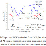 |
Figure 4: Fig. 3: FT-IR spectra of PANI synthesised from 1 M H2SO4, nicotinic acid, or 2-methylnicotinic acid. All samples were synthesised using ammonium persulfate at 0-1°C for 4 hours. The type of polymer is highlighted with various colours as per the key provided Click here to View figure |
Conductivity of Polyaniline
The ability of a material to transfer electrons is called the conductivity (σ); it is the ratio of current density to the electrical field.16 One of the main aims of this work was to investigate the influence of dopants on the electrical properties of PANI. The conductivities of the PANI samples prepared for this study have been measured and are shown in table 1.
Table 1: Conductivities of PANI samples produced from 1 M sulphuric acid, nicotinic acid, and 2-methylnicotinic acid.
|
Polymers |
Dopant |
Conductivity S.cm-1 |
|
Polyaniline |
sulphuric acid |
1.09 |
|
Polyaniline |
Nicotinic acid |
0.63 |
|
Polyaniline |
2-methylnicotinc acid |
0.089 |
Table 1 shows a high conductivity for PANI-H2SO4 (1.09 S.cm-1), whilst the conductivity of PANI-MNA (0.089 S.cm-1) was relatively low due to the weak reaction of MNA with the aniline monomer for steric reasons; MNA is a large molecule compared to H2SO4, which reduces the effectiveness of the electron transfer process. The proton dissociation from the acid is of particular importance due to its effect on the protonation level.43 MNA has a relatively low acid dissociation constant, which results in a decrease in polymer conductivity. If the size of the dopant molecule is large, steric hindrance is increased, which leads to the production of a polymer with low conductivity.44 According to the FT-IR spectra (Fig. 4), it is suggested that MNA is present in the backbone of the PANI synthesised from electrolytes containing MNA. As a result, the conductivity of PANI doped with MNA is significantly decreased. Furthermore, the presence of a methyl group in the MNA (Fig. 5) can have an inductive effect on the carboxylic group, thus reducing the acid dissociation constant.45 This can make polymerisation slow, and due to increased steric hindrance may lead to the production of PANI with a low conductivity, as observed in this work. Another reason for the observed decrease in electrical conductivity of PANI produced from 2-methylnicotinic acid solution could be the increase in the energy gap between the conduction and valence bands; as a result, electrons cannot easily travel into the conduction band, and hence a decrease conductivity is observed. 46
The conductivity of the PANI prepared from the NA electrolyte was 0.63 S.cm-1, which is particularly good compared to the conductivity of the PANI that produced from MNA. This was very likely due to the absence of the methyl group in the NA (see Fig. 5). Therefore, it can be said that polyaniline was successfully prepared from an aqueous NA electrolyte.
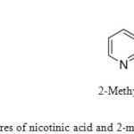 |
Figure 5: Structures of nicotinic acid and 2-methylnicotinic acid Click here to View figure |
Morphologies of polyaniline
The morphologies of the PANI produced with each of the three dopants were studied via SEM. Fig. 6 shows the morphologies of PANI samples prepared from a) 1 M H2SO4, b) 1 M nicotinic acid NA and c) 1 M 2-methylnicoticic acid MNA respectively.
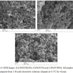 |
Figure 6: SEM images of a) PANI/H2SO4, b) PANI/NA and c) PANI/MNA. All samples were prepared from 1 M acids electrolyte solutions (dopant) at 0-1°C for 4 hours. Click here to View figure |
From Fig. 6, it can be seen that the dopant strongly affected the microstructures and polymer lattice of the PANI samples. A fibrous, homogenous morphology with an open structure was found for PANI/ H2SO4,as shown in Fig. 6 (a). However, the morphology of PANI/NA (Fig. 6 b) shows a non-uniform structure with two regions consisting of small fibrous chains and an agglomerated morphology where it seems that PANI/NA chains have a less porous surface compared to that observed for the PANI/ H2SO4 sample. The morphology of the PANI produced from the MNA electrolyte (Fig. 6c), shows small grain size, connected to each other homogeneously making a large and lumpy structure that might result from the influence of the MNA group. From SEM, it seems that PANI/MNA is a less porous structure than PANI/H2SO4 and PANI/NA. We believe that differences in surface morphology and electrical conductivity are related to the different electrolytes used having hydrophilic (H2SO4) and hydrophobic (NA and MNA) behaviour resulting in formation of polymers with different structural characteristics.
It is clear from the morphology of PANI/H2SO4, that the PANI resembles chains, which previous researchers have suggested is related to the observed increase in conductivity 55,47,48, which appears to be exactly as found in this work; the conductivity of PANI/H2SO4 is significantly larger than that of PANI/NA and PANI/ MNA, as explained in the previous section, where the magnitudes of the conductivities of each of the PANI samples (Table 1) were in qualitative agreement with their observed morphologies (Fig. 6). Generally speaking, previous work in this field suggests that the length of the chain of the polymer can affect the conductivity of PANI. Thus, it was found that conductivity of PANI was decreased when it has a short chain length, which also impacts on the final structure which becomes more compact. 49,50
Thermogravimetric Analysis (TGA)
In addition to the electrical conductivity, it is of particular importance to study the thermal stabilities of the PANI samples produced from different electrolytes. Thermogravimetric analysis is one of the methods that is typically used in this regard, which is achieved by investigating the change in weight of a sample with increasing temperature while also monitoring the degradation of polymers and measure the quantity of water and other volatile materials lost during the process. 51,52 In this work, TGA was used to examine the degradation of the three different PANI samples prepared in addition to having found their electrical conductivities. Fig. 7 shows the thermogravimetric curves found under an N2 atmosphere for PANI samples prepared using 1 M H2SO4, NA and MNA. The results show that there are three major steps of weight loss for each PANI sample. These results are also shown in Table 2. The steps observed are: 1) loss of solvent or water, (2) loss of dopant anion and (3) decomposition of the PANI backbone. This observation is similar to the results are seen in previous work. 52-54
Table 2: The stages of weight loss of PANI samples doped with sulphuric acid, nicotinic acid 2-methylnicotinic acid.
|
Conducting polymer |
Temp. Loss of water / solvent (°C) |
Temp. Loss of dopant anions (°C) |
Temp. Backbone degradation (°C) |
|
PANI/H2SO4 |
97.87 |
288.12 |
473.27 |
|
PANI/NA |
90.08 |
254.46 |
312.94 |
|
PANI/MNA |
– |
287.80 |
359.67 |
The first stage of weight losses is related to the loss of the solvent or water, where the PANI loses any residual water and/or solvent that might be present. PANI is usually prepared using aqueous or non-aqueous electrolytes; consequently, residual solvent molecules that are present inside the polymeric chains are difficult to remove at low temperatures in the drying oven. However, slightly higher temperatures will eliminate them. Therefore, the temperature required to achieve this elimination is typically between 80-120°C.55,56 Table 2 shows that loss of the dopant anion occurred between 200-300°C. The third step is decomposition of the PANI, where the actual backbone of the polymer itself begins to break down. For PANI, this is typically observed between 300-500°C. It is clear from Table 2, and Fig. 7, that the degradation of the PANI synthesised with H2SO4, NA and MNA as electrolytes occurs around 473°C, 312°C and 359°C, respectively. This thermogravimetric analysis indicates better thermal stability of the PANI/H2SO4 than that of PANI/NA and PANI/MNA. The poor thermal stability of PANI/MNA can be explained by the presence of a methyl group in the polymer structure.
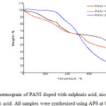 |
Figure 7: TGA thermogram of PANI doped with sulphuric acid, nicotinic acid2-methylnicotinic acid. All samples were synthesised using APS at 0-1oC for 4 hours Click here to View figure |
Conclusion
In this research, different conducting polymers were synthesised successfully from an aniline monomer in different acidic solutions via chemical polymerisation. Polyaniline samples prepared from nicotinic acid and 2-methylnicotinic acid as a dopant have been prepared for the first time. The findings showed that each dopant had a significant effect on the properties of the PANI, producing polymers with different morphology, conductivity and stability. It was found that the conductivity of the PANI that was produced using sulphuric acid was greater than those produced from the nicotinic acid and 2-methylnicotinic acid electrolytes. Furthermore, the thermal stability of PANI/H2SO4 was considerably greater than that obtained from solutions containing NA and MAN. SEM analysis showed that PANI formed from sulphuric acid has an open structure and fibrous porous morphology, whereas polymers formed from NA and MNA have more compact structures and less porosity. The low electrical conductivity of the polyaniline samples produced from NA and MNA electrolytes may be due to the large size of NA and MNA dopant which is present in polymeric matrix causing steric hindrance towards electrons transfer along the backbone of polymer. The polymer structure is also thought to be related to either hydrophilic (H2SO4) or hydrophobic (NA and MNA) behaviour of the dopant. It can be concluded as PANI was successfully produced using NA and MNA as a dopant.
Acknowledgements
The authors would like to thank Kingston University, London for providing the required materials and instrumentals used in this work. They would also like to thank Prof. Peter Food, Dr. Stephen Barton and Dr Zaid Abbas for help, support and notable comments.
References
- Hillman, A. R.; Mohamoud, M. A. Electrochimica acta., 2006, 51, 6018-6024.
CrossRef - Blinova, N. V.; Stejskal, J.; Trchová, M.; Prokeš, J.; Omastová, M. European Polymer Journal., 2007, 43, 2331-2341
CrossRef - Li, K. h.; Diaz, D. C.; He, Y.; Campbell, J. C.; Tsai, C. Applied physics letters., 1994, 64, 2394-2396.
CrossRef - Huang, J.; Virji, S.; Weiller, B. H.; Kaner, R. B. Chemistry–A European Journal., 2004, 10, 1314-1319.
CrossRef - Stenger-Smith, J. D. Progress in Polymer Science., 1998, 23, 57-79.
CrossRef - Yin, X.; Ding, J.; Zhang, S.; Kong, J. Biosensors and Bioelectronics., 2006, 21, 2184-2187.
CrossRef - Holze, R.; Wu, Y. P. Electrochimica acta., 2014, 122, 93-107.
CrossRef - Sazou, D.; Kosseoglou, D. Electrochimica acta., 2006, 51, 2503-2511.
CrossRef - Shakir, I.; Shahid, M.; Rana, U. A.; Warsi, M. F. RSC Advances., 2014, 4, 8741-8745.
CrossRef - Guan, D.; Gao, X.; Li, J.; Yuan, C. Applied Surface Science., 2014, 300, 165-170
CrossRef - Yan, J.; Wei, T.; Shao, B.; Fan, Z.; Qian, W.; Zhang, M.; Wei, F. Carbon., 2010, 48, 487-493.
CrossRef - Xia, X.; Hao, Q.; Lei, W.; Wang, W.; Wang, H.; Wang, X. Journal of Materials Chemistry., 2012, 22, 8314-8320.
CrossRef - Lim, Y.; Tan, Y.; Lim, H.; Huang, N.; Tan, W. Journal of Polymer Research., 2013, 20, 156.
CrossRef - Guimard, N. K.; Gomez, N.; Schmidt, C. E. Progress in Polymer Science., 2007, 32, 876-921.
CrossRef - Wan, M. Conducting polymers with micro or nanometer structure; Springer, 2008.
- Abbas, Z. K., Kingston University, 2009.
- Toshima, N.; Yan, H. Bulletin of the Chemical Society of Japan., 1995, 68, 1056-1063
CrossRef - McCluskey, M. D.; Haller, E. E. Dopants and defects in semiconductors; CRC Press, 2012.
CrossRef - Facchetti, A. Materials Today., 2007, 10, 28-37.
CrossRef - MacDiarmid, A. G.; Epstein, A. J. Faraday Discussions of the Chemical Society., 1999, 88, 317-332
CrossRef - Barbero, C. ; Silber, J. J. ; Sereno, L. Journal of electroanalytical chemistry and interfacial electrochemistry., 1999, 263, 333-352.
CrossRef - Molapo, K. M.; Ndangili, P. M.; Ajayi, R. F.; Mbambisa, G.; Mailu, S. M.; Njomo, N.; Masikini, M.; Baker, P.; Iwuoha, E. I. International Journal of Electrochemical Science., 2012, 7, 11859-11875.
- Margolis, J. M., Conductive Polymers and Plastics, Springer Science & Business Media, 2012.
- Ćirić-Marjanović, G. Synthetic metals., 2013, 177, 1-47.
CrossRef - Hillman, A. R.; Ryder, K. S.; Ismail, H. K.; Unal, A.; Voorhaar, A. Faraday discussions., 2017, 199, 75-99.
CrossRef - Yang, H.; Guo, X.; Birbilis, N.; Wu, G.; Ding, W. Applied Surface Science., 2011, 257, 9094-9102.
CrossRef - Wang, Q.; Zhang, Q.; Chen, B.; Lu, X.; Zhang, S. Journal of The Electrochemical Society., 2015, 162, D320-D324.
CrossRef - Abbott, A. P.; Ballantyne, A.; Harris, R. C.; Juma, J. A.; Ryder, K. S. Physical Chemistry Chemical Physics., 2017, 19, 3219-3231.
CrossRef - Kim, J.-Y.; Lee, J.-H.; Kwon, S.-J. Synthetic metals., 2007, 157, 336-34
CrossRef - Heinze, J.; Frontana-Uribe, B. A.; Ludwigs, S. Chemical Reviews., 2010, 110, 4724-4771.
CrossRef - Wang, Z.; Yuan, J.; Li, M.; Han, D.; Zhang, Y.; Shen, Y.; Niu, L.; Ivaska, A. Journal of Electroanalytica l Chemistry., 2007, 599, 121-126.
CrossRef - Kim, Y.; Fukai, S.; Kobayashi, N. Synthetic metals., 2001, 119, 337-338.
CrossRef - Peng, C.; Zhang, S.; Jewell, D.; Chen, G. Z. Progress in Natural science., 2008, 18, 777-788.
CrossRef - Wallace, G. G.; Teasdale, P. R.; Spinks, G. M.; Kane-Maguire, L. A. Conductive electroactive polymers: intelligent polymer systems; CRC press, 2008.
CrossRef - Molapo, K. M.; Ndangili, P. M.; Ajayi, R. F.; Mbambisa, G.; Mailu, S. M.; Njomo, N.; Masikini, M.; Baker, P.; Iwuoha, E. I. International Journal of Electrochemical Science., 2012, 7, 11859-11875.
- Gospodinova, N.; Terlemezyan, L. Progress in Polymer Science., 1998, 23, 1443-1484.
CrossRef - Sapurina, I.; Stejskal, J. Polymer International., 2008, 57, 1295-1325.
CrossRef - G. Inzelt, Conducting Polymers: A New Era in Electrochemistry, Springer-Verlag Berlin Heidelberg, 2008.
- Bian, L.-J.; He, H.-L.; Liu, X.-X. RSC Advances., 2015, 5, 75374-75379.
CrossRef - Bakhtiarian, E.; Foot, P. J.; Miller Tate, P. C. Progress in Rubber, Plastics & Recycling Technology., 2016,32, 183-189.
CrossRef
- Bhat, N. V.; Seshadri, D. T.; Phadke, R. S. Synthetic metals., 2002, 130, 185-192
CrossRef - Bian, L.-J.; Zhang, J.-H.; Qi, J.; Liu, X.-X.; Dermot, D.; Lau, K.-T. Sensors and Actuators B: Chemical., 2010, 147, 73-77
CrossRef - Kim, J.; Ju, H.; Inamdar, A. I.; Jo, Y.; Han, J.; Kim, H.; Im, H. Energy., 2014, 70, 473-477.
CrossRef - Catedral, M.; Tapia, A.; Sarmago, R.; Tamayo, J.; Del Rosario, E. Science Diliman 2007, 16.
- Cochet, M.; Corraze, B.; Quillard, S.; Buisson, J.; Lefrant, S.; Louarn, G. Synthetic metals., 1997, 84, 757-758.
CrossRef - Catedral, M.; Tapia, A.; Sarmago, R.; Tamayo, J.; Del Rosario, E. Science Diliman., 2007, 16.
- Li, Q.; Liu, J.; Zou, J.; Chunder, A.; Chen, Y.; Zhai, L. Journal of Power Sources., 2011, 196, 565-572.
CrossRef - Mark, J. Polymer Engineering & Science., 1996, 36, 2905-2920
CrossRef - Lin, Y.-C.; Hsu, F.-H.; Wu, T.-M. Synthetic metals., 2013, 184, 29-34.
CrossRef - Saranya, S.; Selvan, R. K.; Priyadharsini, N. Applied Surface Science., 2012, 258, 4881-4887.
CrossRef - Ghosh, P.; Siddhanta, S. K.; Haque, S. R.; Chakrabarti, A. Synthetic metals., 2001, 123, 83-89
CrossRef - Rodrigues, P. C.; de Souza, G. P.; Neto, J. D. D. M.; Akcelrud, L. Polymer., 2002, 43, 5493-5499.
CrossRef - Campos, T.; Kersting, D.; Ferreira, C. Surface and coatings Technology., 1999, 122, 3-5.
CrossRef - Lili Ding, Xingwu Wang, R.V. Gregory, Synthetic Metals 104 1999 73–78.
CrossRef - Wang, Q ; Qian, X.; Wang, S.; Zhou, W.; Guo, H.; Wu, X.; Li, J.; Wang, X. Synthetic metals., 2015, 199, 1-7.
CrossRef
- Ghosh, P.; Siddhanta, S. K.; Haque, S. R.; Chakrabarti, A. Synthetic metals., 2001, 123, 83-89.
CrossRef

This work is licensed under a Creative Commons Attribution 4.0 International License.


