Design and Fabrication of Temperature Sensor for Weather Monitoring System using MEMS Technology
Veeramani P1, Vimala Juliet A1, Sam Jebakumar J1 and Jagadish R2
1Department of Electronics and Instrumentation Engineering, SRM Institute of Science and Technology, Kattankulathur, Kanchipuram.
2Research Institute, SRM Institute of Science and Technology, Kattankulathur, Kanchipuram.
Corresponding Author E-mail: veerasrm.1993@gmail.com
DOI : http://dx.doi.org/10.13005/ojc/340537
Article Received on : 19-03-2018
Article Accepted on : 17-08-2018
Article Published : 08 Oct 2018
In this paper, Micro Electro Mechanical System (MEMS) based temperature sensor is designed and fabricated for weather monitoring system at troposphere level. In this design we have used meander shape, because it is easy to vary the length. We have optimized the length in this design. Due to certain advantages like low cost, easily available, high melting and boiling point, molybdenum material is used for fabrication of this design. The four meander type temperature sensors are designed with various dimensions of sizes in 6.7mm×4mm, 9.5mm×4mm, 5.2mm×4mm, 6.5mm×4mm. The Temperature Coefficient of Resistance (TCR) values for four various sensors mentioned above are 3.4 ×10⁻⁴ C-1, 3.7×10⁻⁴ C-1, 7.0×10⁻⁴ C-1, 7.5×10⁻⁴ C-1. For radiosonde applications the sensor must have high sensitivity, high degree of accuracy, good linearity and with better TCR values. The experimental results are better for dimension 6.7mm ×4mm for all characteristics mentioned above. The practical results are compared with the theoretical values.
KEYWORDS:MEMS; Radiosonde; Temperature Sensor
Download this article as:| Copy the following to cite this article: Veeramani P, Juliet V. A, Jebakumar S. J, Jagadish R. Design and Fabrication of Temperature Sensor for Weather Monitoring System using MEMS Technology. Orient J Chem 2018;34(5). |
| Copy the following to cite this URL: Veeramani P, Juliet V. A, Jebakumar S. J, Jagadish R. Design and Fabrication of Temperature Sensor for Weather Monitoring System using MEMS Technology. Orient J Chem 2018;34(5). Available from: http://www.orientjchem.org/?p=50360 |
Introduction
Micro Electro Mechanical Systems (MEMS) is a technology to develop micro devices and micro systems. MEMS are used for miniaturization of sensors. MEMS components are generally in size from micrometers to millimeters. The reliability of these sensors have been increased considerably by integrating them with IC technology.1,2 Micro-Electro Mechanical System fabrication technology is employed to reduce size of the sensor, cost of electronic devices in various applications, it is the important thing that the electronic device must be stable, portable, and flexible. To design a temperature sensor for weather monitoring in radiosonde application using MEMS technology. The temperature sensor was designed to measure the troposphere level. Nowadays the sensors used in radiosonde application are big in size. The temperature sensor is designed to reduce the size and cost of the sensor. In order to sense these conditions, an appropriate sensing method has to been utilized in order to achieve accurate outputs in a study manner.
Basically sensors can be classified into two types. One is active sensor and another one is passive sensor. Active sensor is self generating. Passive sensor is modulating. The Active sensor converts input energy into output signal and it does not require any external supply. The Passive sensor requires additional power source to converts input energy into an output signal. The function of a temperature sensor can be classified into three different modes. They are physical, mechanical and optical. However, our target is to obtain electrical outputs. The electrical sensor is used for measuring the temperature. One of the simplest and easiest electrical technologies for measuring temperature is by using resistive measurement. Resistance Temperature Detector (RTD) and thermistor is the temperature sensor which changes electrical resistance with temperature. In this method works on the fact that resistivity of the material is temperature dependent. The temperature of the RTD ranges from -200°C to 600°C with an excellent accuracy over a wide temperature range.3,4
Methodology
Theory of Temperature Sensor
The resistance of the metal is described as,
R = ρL/A……………….. (1)
If temperature of the RTD varies linearly, then the relationship between the measured resistance and the temperature change5,6,7 can be expressed as
Rt = R0 [1+α (t- t0)]…… (2)
Where,
R suffix t is the resistance at t°C
R suffix 0 is the resistance at 0°C
α is the temperature coefficient of resistance
t is the temperature to be measured
t0 is the initial temperature
Design of Micro Temperature Sensor
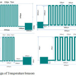 |
Figure 1: Design of Temperature Sensors. |
The temperature sensor has been analyzed with different dimensions. When its length increases the resistance value will also increase proportionally. The important thing to be considered is Temperature Coefficient of Resistance (TCR). Where TCR is defined as the resistance change factor per degree Celsius of temperature change. By changing the temperature the resistance value is recorded. The TCR value was calculated based on these recorded values.
Design of Temperature Sensors Using Comsol
A Multiphysics numerical stimulator COMSOL was used to design and stimulate the sensor design. In this section the design aspects is discussed. Joule heating module is selected as the physics for the model. Fixed current and temperature are assumed at the end of the heater. The current supplied is in few hundred microns (0.07A). The electrical current converted into heat flows through resistor.8,9 The work presents the corresponding electrical potential of four temperature sensors.
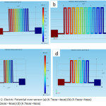 |
Figure 2: Electric Potential over sensor (a) (6.7mm×4mm) (b) (9.5mm×4mm) (c) (5.2mm×4mm) (d) (6.5mm×4mm). |
Figure 2 shows how the electrical potential is distributed for four different dimensions. Figure 3 shows dimensions of sensor. Whenever the length increases the resistance value also increases. Figure 4 shows relationship between the resistance and input temperature of molybdenum based temperature sensor and observed resistance of the sensor increase linearly with increase in input temperature for the specified ranges.
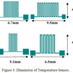 |
Figure 3: Dimension of Temperature Sensor. |
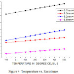 |
Figure 4: Temperature vs. Resistance. |
The temperature sensor is of size in 6.7mm×4mm which linearly increases in resistance value (7.208 to 8.731 Ω) according to the input temperature (-100 to 500°C). It works on the principle of resistance temperature detector. The temperature coefficient of resistance is 3.4×10⁻⁴ C-1. The sensor is of size 9.5mm×4mm which linearly increases in resistance (3.104 to 3.813 Ω) according to the input temperature (-100 to 500°C). The temperature coefficient of resistance is 3.7×10⁻⁴ C-1. The resistance of the sensor is directly proportional to the length of the sensing material molybdenum. The sensor is of size 5.2mm×4mm which linearly increases in resistance value(3.416 to 4.929 Ω) according to the input temperature (-100 to 500°C). The temperature coefficient of resistance is 7.0×10⁻⁴ C-1.The sensing material consists of size of 75µm. The temperature sensor has 6.5mm×4mm which linearly increases in resistance (1.482 to 2.191 Ω) according to the input temperature (-60 to 60°C). The temperature coefficient of resistance is 7.5 ×10⁻⁴ C-1.
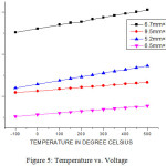 |
Figure 5: Temperature vs. Voltage. |
In Figure 5, the temperature sensor consists is of size 6.7mm×4mm which linearly increases in voltage value (0.504 to 0.611 V) according to the input temperature (-100 to 500°C). When passing a small amount of current 0.07 A to RTD generates a voltage across the RTD. By measuring the voltage the resistance and temperature value is determined.
The sensor has 9.5mm×4mm which is linearly increases voltage value (0.217 to 0.266 V) according to the input temperature (-100 to 500°C). It is gradually increases according to the input temperature. The sensor consists of size in 5.2mm×4mm which linearly increases in voltage value (0.239 to 0.345 V) according to the input temperature (-100 to 500°C). It gradually increases according to the input temperature. The sensor has 6.5mm×4mm which is linearly increases in voltage value (0.103 to 0.153 V) according to the input temperature (-100 to 500°C).
Theoretical Calculation
According to Callender-Van Dusen equation, the RTDs are used to measure temperature by correlating the resistance. This correlation between the resistance and temperature of RTD is described by a Callender-Van Dusen equation.
The Callender-Van Dusen is an equation to determine resistance and temperature relationship at both positive and negative temperatures.
At positive temperature
Rt = R0 [1+At+Bt2]………………. (3)
At Negative temperature
Rt = R0 [1+At+Bt2+C(t-100)3]…….(4)
Where A, B, C are Callender Van Dusen constants. The alpha, beta and delta are constants to determine the constant values of A, B and C. Equation (4) is typically used for temperature below 0°C. Where equation (3) is used for temperature above 0°C. When below 0°C is used in equation (3) the error is calculated resistance value. So we can use equation (4) for below 0°C.10-12
According to the calculation of each temperature sensor the resistance value is increased linearly with input temperature and the sensor 6.7mm×4mm has high sensitivity. The resistance and voltage value is calculated according to the temperature change.
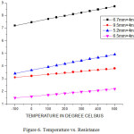 |
Figure 6: Temperature vs. Resistance. |
According to Callender Van Dusen equation, the positive and negative temperature has different formula to calculate the resistance value. In figure 6, the sensor 6.7mm×4mm shows that resistance (7.20 to 8.73 Ω) is increased linearly according to the input temperature (-100 to 500°C). The size of the sensor is 9.5mm×4mm which linearly increases in resistance (3.10 to 3.81 Ω) according to the temperature (-100 to 500°C). When compared to 6.7mm×4mm it has lower resistance value. The 5.2mm×4mm sensor which shows linearly increases resistance (3.41 to 4.92 Ω) according to the input temperature (-100 to 500°C). The resistance is linearly increases (1.482 to 2.19 Ω) according to the input temperature (-60 to 60°C) on sensor 6.5mm×4mm. The TCR value is 7.0×10⁻⁴ C-1. So the resistance change is good according to degree temperature changes and sensitivity is good in 6.7mm×4mm.
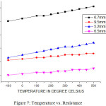 |
Figure 7: Temperature vs. Resistance. |
In Figure 7, the temperature sensor consists of size 6.7mm ×4mm which linearly increases voltage value (0.50 to 0.61 V) according to the input temperature. The sensor consists of size 9.5mm×4mm which linearly increases voltage value (0.217 to 0.266 V) according to the input temperature. The sensor consists of size in 5.2mm×4mm which linearly increases voltage value (0.23 to 0.34 V) according to the input temperature. The sensor which as 6.5mm×4mm which linearly increases voltage (0.10 to 0.15 V) according to the input temperature. The small amount of current through a sensor generates a voltage across the sensor.
Experimental Details
Fabrication of mask
The laser writer Heidelberg MPG 501 was used for photo mask fabrication with commercially available chrome photo mask blank. A 390 nm laser was used with the writing speed of 50mm²/minute. The photomask layout for the micro fabrication of temperature sensor was designed using CleWin software. The fabricated photomask is shown in Figure 9 with four different sensing arm length variations.
Choice of Substrate and Photoresist Materials
Silicon, being a good structural material with ideal semiconducting properties and mechanical stability was chosen as the substrate. Silicon wafers are annealed at 1000°C for 30 min in oxygen atmosphere to form an oxide layer on the surface.
ARP- 3250, a positive photoresist (ALLRESIST, GmbH, Germany) was chosen for the preparation of resist template. ARP-3250 shows better integrity and resolution of the shapes for micro devices.13 The photoresist was spin coated (SpinNXGP1) at 4000 rpm for 30 sec. to grow~8 µm thick resist. The evaporation of excess solvent was done by prebaking the resist coated substrates at 90°C for 8 minutes.
Fabrication of resist template
The desired patterns in the photomask were transferred to the resist by utilizing ultraviolet radiation. The photo mask was placed intact with resist coated silicon substrates. The UV exposure was done using OAI, USA flood exposure tool, model 0. The UV was exposed with the controlled power of 10 mW/cm2 for a time period of 25 s. On completion of the UV exposure, the photo resist was developed using developer solution. The solution was the mixture of AR300-26:DI water in the ratio of 1:5.The development was carried out for a maximum duration of 200 s. The desired sensor design thus transferred to the photoresist acts as template (shown in Fig. 11) for subsequent processes.14
Deposition of molybdenum
The molybdenum was deposited using DC sputtering process. The base pressure of chamber was 5×10⁻⁵ mbar. Under Argon gas supply, the molybdenum was coated for 3 minutes with the working pressure of 8×10⁻² mbar. The optical image of deposited molybdenum on the photoresist template is shown in Figure 12.
Resist removal
The deposition of molybdenum was followed by resist removal process. Resist remover AR300-76 was used to remove the sacrificial resist. Removal process was done for 3-5 seconds in ultra-bath sonicator at near room temperature. After resist removal the substrate was cleaned using DI water for several times. The optical microscope images of the temperature sensor fabricated on the SiO2 substrate is shown in Figure 13. Repeated washing with DI water was done to remove residual part of resist from the surface.
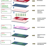 |
Figure 8: Fabrication process of temperature sensor. |
Results and Discussion
The micro-temperature sensor (shown in Figure 14) with sensing arm of 9.5mm×4mm along with contact pads was fabricated using microlithography technique.
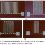 |
Figure 9: Photomasks with variation in sensing arms (a) 9.5mm×4mm (b) 6.7mm×4mm (c) 6.5mm×4mm (d) 5.2mm×4mm. |
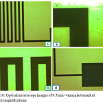 |
Figure 10: Optical microscope images of 9.5mm×4mm photomask at different magnifications. |
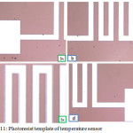 |
Figure 11: Photoresist template of temperature sensor. |
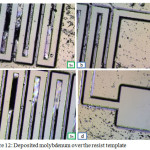 |
Figure 12: Deposited molybdenum over the resist template. |
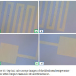 |
Figure 13: Optical microscope images of the fabricated temperature sensor after complete removal of sacrificial resist. |
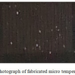 |
Figure 14. Photograph of fabricated micro temperature sensor. |
Conclusion
The novelty of this work is to reduce the size of the sensor in a radiosonde device by using MEMS based devices. The results obtained in comsol multiphysics software for the sensors 6.7mm × 4mm and 5.2mm × 4mm shows that the resistance changes linearly for a linear change in temperature and the TCR value are 3.4 ×10⁻⁴ C-1 and 7.0 ×10⁻⁴ C-1 respectively. The sensor 6.7mm × 4mm has high resistance change according to the input temperature and sensitivity is also higher. The molybdenum based temperature sensor was designed successfully using comsol multiphysics. The fabrication of 9.5mm×4mm sensor was done experimentally. A vacuum environment setup is made to measure the change in resistance of the temperature sensor as a function of temperature. The simulated results will be verified experimentally for the fabricated temperature sensor.
Acknowledgement
My sincere gratitude and thanks goes to SRM Institute of Science and technology and Department of electronics and instrumentation for providing the sources and guidance. The authors would like to warmly thank Dr. P. Malar from Research institute & Indian Institute of Technology, Bombay for helping the device fabrication. And I would like to thank Dr. A Vimala Juliet and Mr. J Sam Jeba kumar for guidance and valuable suggestions. And Special thanks go to MEMS design centre. Also, I would like to thank my friend Abdurrashid shuaibu Hassan for sharing his knowledge.
References
- Rong-Hua Ma; Yu-Hsiang Wang; Chia-Yen Lee; “Wireless Remote Weather Monitoring System Based on MEMS Technologies”, Sensors, 2011, 11, 2715-2727
CrossRef - Takayuki Fujita; Kazusuke Manenaka; “Integrated multi-environmental sensing system for the intelligent data carrier”, Sensors and Actuators A:Physical, 2002, 97-98, 527-534.
CrossRef - Lee, C.Y.; “MEMS-Based Temperature control Systems for PCR Applications”, Int. J. Nonlin. Sci. Num. Simulation, 2002, 3, 215-218.
CrossRef - SuyanXiao; Lufeng Che; Xinxin Li; Yuelin Wang; “A cost effective flexible MEMS technique for temperature sensing”, Micro electronics journal, 2007, 38, 360-364.
CrossRef - Zelijko Hocenski; Ljubivoj Cvitas; Zelijko Lasinger; “Comparision of methods for nonlinearity correction of platinum resistance thermometer”, SICE Annual Conference, 2008, 3151-3154.
- Clifton L. Roozeboom; Bridget E. Hill; Vu Ang Hong; Chae Hyuck Ahn; Eldwin J.Ng; Yushi Yang; Thomas W.Kenny; “Multifunctional Integrated Sensors for Multiparameter Monitoring Applications”, Journal of Micro Electro Mechanical Systems, 2015, 24, 810-821.
CrossRef - Edval J.P. Santos; Isabela B. Vasconcelos; “RTD based Smart Temperature Sensor: Process Development and Circuit Design”, Microelectronics, 2008, 11-14.
- Phatthanakun, R.; Deekla, P.; Pummara, W.; Sriphung, C.; Pantong, C.; Chomnawang, N.; “Design and Fabrication of Thin Film Aluminium Microheater and Nickel Temperature Sensor”, Nano Engineered and Molecular Systems, 2012, 112-115.
- Bakker, A.; “CMOS Smart Temperature Sensor An Overview”, Sensors, 2002, 1423-1427.
- Zhen Fang; Zhan Zhao; Lidong Du; Jiangang Zhang; Cheng Pang; Daoqu Geng; “A portable Micro Weather Station”, International Conference on Nano/Micro Engineered and Molecular systems, 2010, 379-382.
- Huang, J.B.; Tung, S.; Ho C.M. Liu, C.; Tai, Y.C.; “Improved micro thermal shear-stress sensor”, IEEE Transactions on Instrumentation and Measurement, 2006, 45, 570.
CrossRef - Rong-Hua Ma.; Dung-An Wang; Tzu-Han Hsueh; Chia-Yen Lee; “ MEMS based flow rate and flow direction sensing platform with integrated temperature compensation scheme”, Sensors, 2009, 9, 5460-5476.
CrossRef - Malar, P.; Zhao, J.; Van Kan, J.A.; “ Fabrication of metallic stamps for injection moulding applications by combining proton beam writing and UV lithography”, Applied Surface Science, 2012, 258, 4191-4194
CrossRef - Sivasangari Sathiamoorthi.; Kunal, J.; Tiwari.; “ Photo resist template fabrication and template assisted growth for surface patterning of technologically important Cu2ZnSnSe2 thin films” Materials and Design, 2017, 127, 126-133.
CrossRef

This work is licensed under a Creative Commons Attribution 4.0 International License.
![]()
A New Edition of Web of Science
Journal Impact Factor
2022: 0.5
Five Year: 0.8
Journal is Indexed in

Cabells Whitelist
![]()


