Calcareous Deposits and Effects on Steels Surfaces in Seawater – A Review and Experimental Study
Cleophas Akintoye Loto1,2
1Department of Mechanical Engineering, Covenant University, Ota, Nigeria.
2Department of Chemical, Metallurgical and Materials Engineering, Tshwane University of Technology, Pretoria, South Africa.
Corresponding Author E-mail: akinloto@gmail.com
DOI : http://dx.doi.org/10.13005/ojc/340514
Article Received on : 31-05-2018
Article Accepted on : 15-08-2018
Article Published : 02 Oct 2018
This article reports the various research investigations by many scientists on seawater composition, particularly, on calcareous deposits and effects on mild and austenitic stainless steels in seawater and relative to their protection against corrosion. The main areas of attention include the factors and the mechanisms that influence the formation of calcareous deposits; solubility of calcite and aragonite, calcareous deposition and the growth kinetics effects of temperature and magnesium. Also reviewed are the solution behaviour of carbonate materials and the factors that influence calcium carbonate precipitation. A review of an extensive field and laboratory investigation on the performance evaluation of super austenitic stainless steels in seawater was also reported. Field tests and laboratory examinations were used to determine Field tests and laboratory examinations were used to determine the corrosion susceptibility of selected super austenitic stainless steels in seawater. The tube(s) surface biofilm enrichment at the different areas of the tube was confirmed with EDAX spectroscopic analysis as consisting of chemical elements such as Ca, Mg, Cl, P and Si. Analysis with X-ray diffraction confirms more enrichment of biofilm in the steam chamber with Fe, Ca, and Mg than the outlet tube biofilm. The presence of CaCO3 – calcite and aragonite was confirmed as the major composition of the calcareous layer deposited on the metal’s surface.
KEYWORDS:Biofilms; Calcareous Deposits; Calcium Carbonate; Corrosion; Magnesium Hydroxide; Seawater; Steel
Download this article as:| Copy the following to cite this article: Loto C. A. Calcareous Deposits and Effects on Steels Surfaces in Seawater – A Review and Experimental Study. Orient J Chem 2018;34(5). |
| Copy the following to cite this URL: Loto C. A. Calcareous Deposits and Effects on Steels Surfaces in Seawater – A Review and Experimental Study. Orient J Chem 2018;34(5). Available from: http://www.orientjchem.org/?p=50086 |
Introduction
The usefulness of seawater is multifarious especially in the areas of transportation, holding engineering infrastructures, telecommunications, and cooling reservoir in diverse manufacturing and engineering services and in military (naval) activities, water drinking through desalination process, fishing, and other marine applications/utilization. Seawater is a complex mixture of about 97% water and 3% salty and smaller amounts of other substances which include organic and inorganic materials, particulates and some atmospheric gases. It is made up of the oceans and seas and covers more than 70% of the earth’s surface. Natural seawater composition consists of different many constituents such as: chloride (Cl–), sulphate (SO42-), bicarbonate (H–CO32+), bromine (Br+), fluoride (F–), sodium (Na+), magnesium (Mg2+), calcium (Ca2+), potassium (K+), and strontium (Sr+) ions.1-10 It also consists of boric acid. When calcium and magnesium are supersaturated in seawater, they form calcium carbonate (CaCO3), magnesium carbonate (MgCO3) and magnesium hydroxide Mg (OH)2. The different forms of calcareous deposits have different structures and form under different parameters.
Among the various constituents/compounds, CaCO3 is known to be at saturated or supersaturated level in seawater, depending on the depth of the sea and/or the season, etc. Corrosion of metallic structures in seawater is widely known. Calcareous deposits such as mentioned above, which consist principally of CaCO3; MgCO3 and Mg(OH)2, are solid products that promote a physical barrier against oxygen diffusion, hence decreasing the corrosion rate, and thus providing effective and efficient cathodic protection in submerged ocean situation.
In this write-up, a collection of some findings from different researchers, regarding the solubility, precipitation, effect of temperature and growth, kinetics, etc., of calcareous deposits, both in field and laboratory experimental investigations is presented.1-16
Factors that Influence Formation/Precipitation of Calcareous Deposits
In general, several factors are known to influence the formation of calcareous deposits, and these include: potential, current, pH, temperature, pressure, and seawater chemistry, flow and time. It has been widely reported1-20 that calcium carbonate becomes less soluble under conditions which increase the temperature or pH of sea water. Calcium and magnesium carbonates and hydroxides are precipitated on cathodic surfaces, as in cathodic protection and in galvanic couples, as the result of induced increases in the ionic products at the electrode. These authors also reported that the deposits resulted from an increase of a pH of the electrolyte adjacent to the metal surface. This phenomenon was explained to be as a result of the cathodic current; and the solubility limit of most inorganic compounds, such as CaCO3, MgCO3 and Mg (OH)2, that decreases with increasing pH.5 Oxygen depletion in the seawater was also reported to be a cause of pH increase.9 In addition, where the balance between the calcium compound and the CO2 in sea water is disturbed, abnormal deposition of CaCO3 on metal surfaces occurs.7
Various instrumentations/equipment including the Scanning Electron Microscopy (SEM), Energy Dispersive Spectroscopy (EDS) and X-Ray Diffraction (XRD) were used to investigate the effect of current density, coating time and attachment of steel mesh on composition ratio, structure and morphology of the electrodeposited films. Further instrumentations/equipment used for the characterization of the calcareous deposits formed include Field Emission Gun Scanning Electron Microscope (FEG SEM) and Electrochemical Impedance Spectroscopy (EIS).
Mechanism of Calcareous Deposit Formation
The importance of calcareous deposit made some researchers to give a mechanistic explanation of its formation.5,10 According to,5 the most important cathodic reaction is oxygen reduction where aerated sea water was used for polarization of metals in which ΦH<Φ <Φcorr, where Φcorr is the corrosion potential and ΦH is the reversible hydrogen potential:
1/2H2O + 1/4O2 + e– OH– (1)
The hydrogen reaction also becomes important if polarization shows that Φ <ΦH. Thus
H2O + e– → H + OH– (2)
The hydroxyl ion is a product for the two reactions above; and pH at the metal/electrolyte interface increases. With this occurrence, the ionic products of various compounds increase until the respective solubility product is exceeded. The important reactions for calcium carbonate specifically are:
Thus, an increase in pH, as the above authors further explained, like that resulting from a cathodic current, alters the natural buffer reactions of sea water and displaces Reaction (4) and (5) to the right. Consequently, carbonate ions are more available; Reaction (3) is shifted to the left; and precipitation occurs.2 defined the degree of saturation (Ω) CaCO3 as:
![]()
Where Ksp is the solubility product for the reaction:
CO3-2 + Ca+2 = CaCO3 (ppt) (7)
Solubility of Calcite and Aragonite
Direct measurement of the solubility of calcite in sea water was considered difficult and irreproducible because of kinetic factors that inhibit the attainment of true, reversible equilibrium,21 to be able to determine the state of saturation of a given seawater sample, the following shipboard measurements need to be made: temperature; pressure (depth); salinity; the concentration of Ca++ (which can be calculated from salinity); and any two of the four parameters, vi: pH, Pco2 (partial pressure of carbon dioxide), ΣCO2 (sum of the concentrations of dissolved CO2, H2CO3, HCO3 and CO32-) and Ac (carbonate alkalinity equal to the concentration of HCO3– plus twice the concentration of CO32–). From these measurements, saturation state(s) can be calculated using equilibrium constants for the solubility of CO2 (if Pco2 is measured, the dissociation of H2CO3 to HCO3– and CO32 and the solubility of CaCO3.
At different times, various researchers22,23 had done calculations for the CaCO3 solubility (in seawater). Calcite behaves in sea water in a manner analogous to that of an irreversible electrode of low exchange current. Near equilibrium in both cases, there is a “flat” region of very slow reaction which renders exceedingly difficult, the determination of equilibrium solubility (in the case of calcite) and equilibrium potential (in the case of an irreversible electrode). Berner21 suggested the way out of the calcite dilemma is to measure the solubility of aragonite in seawater, which behaves more reversibly than calcite (Mg does not inhibit aragonite precipitation), and calculate the solubility of calcite from a knowledge of the solubility difference between calcite and aragonite in other Mg – free solutions where calcite behaves reversibly.
Morse et al24 also presented detailed discussion of the methods and problems of calculating the saturation state of seawater, with respect to the calcium carbonate phases – calcite and aragonite. Theoretical calculation had been carried out by several investigators, for example as in25,26 and they attempted to measure the relationship between CaCO3 supersaturation and the rate of homogeneous nucleation.27,28
Effects of Temperature and Magnesium ions on Calcareous Deposition
Many researchers had reported on various effects of some notable variables affecting calcareous formation. These variable factors include seawater chemistry, pH, velocity, current density, potential, water depth, and surface preparation on calcareous formation.1,3,5 The effect or influence of temperature on calcareous deposition2 had not provided much information. However, Lin and Dexter2 have worked on this aspect and their finding among others is hereby very briefly reviewed.
The focus of research studies of the above mentioned authors was based on the mechanism whereby a decrease in water temperature caused less deposition and the Ca/Mg ratio of the deposit to decrease. These factors also caused a change in the protective properties of the deposit. The work was done on a polarized steel surface. They also reported that the free magnesium ions in seawater were the primary agents inhibiting the low temperature formation of calcareous deposits. At temperatures <˜ 10°C, protective deposit was thus formed in seawater. They also found that Ca/Mg ratio needed to be increased to protect the deposits formed in cold water. The ratio decreases as the temperature decreases. Furthermore, they determined that magnesium inhibition was stronger at lower temperature as with 0 versus 25. Aragonite was the major deposit form of CaCO3 at temperature greater than 25°C, while calcite deposited more at low temperature29
Reviews from the work of these researchers further showed that Mg hindered both nucleation and crystal growth of calcite, but according to Berner30 only nucleation of aragonite was hindered. Bischoff31 showed that aragonite nucleation became more hindered with increasing Mg concentration at 25°C. At lower temperatures, calcite was the major form of deposition and magnesium hindered both calcite nucleation and growth. This made it less for deposit to be found at low temperatures. In addition, since sulphate, SO42-ions are known to form complexes, the presence of sulphate ions in seawater could cause a decrease in the concentration of free Mg+2 ions in seawater relative to that in NaCl/Ca/Mg solution. Bischoff31 was of the opinion that calcareous deposits could dissolve at the lower temperature. Also, the degree of saturation increased when the temperature was changed from 3 to 25°C and deposits formed. When placed in deep water, a deposit formed in warm surface water could rapidly dissolve.
Calcium Carbonate Growth Kinetics in Seawater
Although a number of studies had been made on the growth rate of calcium carbonate from supersaturated solutions other than seawater33-35 the results were generally not applicable to calcium carbonate growth kinetics in seawater because of magnesium effect. It had been found that magnesium has a strong effect on calcite growth kinetics27,31,36; and on organics37-40; and phosphonates.40,41 Berner et al.,40 had also expressed that variations in organic and phosphate concentrations occurring in the ocean could cause changes in precipitation rates in excess of an order of magnitude.
Solution Behaviour of Carbonate Materials in Seawater and the Solubility of Calcite in NaCl Solution at High Temperature
Weyl36 has performed a large number of experiments demonstrating that carbonate minerals in seawater do not behave as homogeneous thermodynamic phases. He found that the external solution does not come to equilibrium with the mineral phase introduced; rather, the surface layers of the solid adjust themselves to the aqueous environment. This behavior was demonstrated both in laboratory experiments and in field observations.
Ellis [1963] worked on the solubility of calcite in sodium chloride solutions at high temperatures. He determined the solubility of calcite at controlled carbon dioxide pressures in sodium chloride solutions of 0.2, 0.5, and 1.0 molal for temperatures between 120°C and 320°C. To interpret the results, he used his other recent solubility results for carbon dioxide in water and salt solutions, together with earlier information on calcite in natural hydrothermal solutions was found to be significantly higher than in salt solutions of comparable ionic strength. Complexing of calcium with silica was suspected. The solubility product for calcite was given for temperatures between 25°C to 250°C and also the values of the mean activity coefficient for the calcium and bicarbonate ions over the same temperature interval and ionic strengths up to molal.
Calcareous Deposits and Under-Deposit Corrosion of Super Austenitic Stainless Steel in Seawater- A Field And Laboratory Study/Analysis Review
Experiments/ Field Investigation
This section summarises/reviews an extensive field and laboratory investigations on the performance evaluation of super austenitic stainless steels in seawater. As previously reported,42 pitting and crevice corrosion susceptibility of selected super austenitic stainless steels in seawater were determined by field tests and laboratory examinations / analysis. The inner surfaces of the steel tubes were exposed to flowing seawater in a specially designed test rig which was located at the HBOI – Harbour Branch Oceanic Institution, Florida. The tubes were specially fitted in the test rig in such a way as to perform uniform flow of the seawater which was pumped through. The steam chamber part of the rig about 0.305 metres long was located in about the middle portion of the tubes length and at which a predetermined steam temperature was maintained. Several tests runs were made and each lasting for 60 days averagely. The predetermined water flow rate varied from one test run to another.
After splitting of the tubes in the laboratory, each split tube was examined with optical macroscope (Wild M3C Model). Scanning electron microscope (SEM) was used to examine some of the tubes at portions for pits, etc. Analysis of the corrosion deposit was performed with the SEM equipped with Energy Dispersive Spectroscopy (EDS) and also with X-ray Diffraction (XRD).
Results and Discussion
From the previous report,42 and as summarized and reviewed above, all the alloys were found to be generally corrosion resistant, but substantial crevice corrosion occurred under the strongly adherent calcareous layers deposited in the steam chamber portion of the tubes as observed in one of the runs. Schematic drawing of the split tubes is presented in Fig. 1(a) and the samples collected from the test rig at the steam chamber are presented in Fig. 1(b).
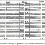 |
Figure 1a: Schematic drawing of split tubes after withdrawal from the test rig42 |
The tubes used include 904L (N08904), 254 SMO (531254), AL6XN (N08367), 925HMO (N08925) types of austenitic stainless steels/ alloys. Their chemical compositions are presented in Table 2. The test conditions are presented in Table 3.
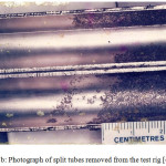 |
Figure 1b: Photograph of split tubes removed from the test rig42 |
Table 1: Chemical Compositions of Super Austenitic Stainless Steel.
| Tube No | Alloy/UNS |
ELEMENTAL COMPOSITION (%) |
|||||||||
| Cr | Ni | Mo | Cu | Mn | C | P | S | Si | N | ||
| 1 | 904L(08904) | 19.0-23 | 25 | 4.5 | 1.5 | 2.0 | 0.02 | .045 | .035. | 1.0 | – |
| 2 &5 | 254SMO(S31254) | 19.5-20.5 | 18 | 6.25 | 1.0 | 1.0 | 0/02 | 0.03 | .01 | .80 | .20 |
| 3 &7 | AL6XN(088367) | 20-22 | 24.5 | 6.5 | – | 2.0 | 0.03 | 0.04 | .03 | 1.0 | .23 |
| 4 &6 | 1925HMO(N908925) | 24-26 | 20 | 6.5 | 1.0 | 1.0 | 0.02 | .045 | .03 | .5 | .20 |
Table 2: Test Conditions.
| Run # | Days | Steam Temp.(°C) | Water flow rate (m3/s) |
| 4 | 59 | 140-160 | 4.5 |
| 5 | 64 | 162 | 4.5 |
| 6 | 61 | 160 | 9 |
| 7 | 60 | 130 | 1 |
| 8 | 61 | 160 | 9 |
According to the reported work as referenced above, that is,42 the biofilm on the inner surface of all the tubes was in general thick but easily removed with hand brush and water. The biofilm in the steam chamber portion was either very light or non-existent or with strong adherent calcareous deposit as observed in one of the test runs. What seemed to be out- of- trend result was obtained in one of the alloy tube test runs at the steam chamber where biofilm was very strongly adherent to the metal surface for all the tubes.
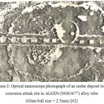 |
Figure 2: Optical macroscope photograph of an under deposit local corrosion attack site in AL6XN (NO83677) alloy tube (Glass ball size = 2.5mm)42 |
Located under the adherent biofilm, were different forms of corrosion attack, mainly macroscopic. All the tubes had corrosion attack under the deposit but to varying degrees. An example of such a corrosion attack under the calcareous deposit is presented in Fig. 2. The corrosion attack concentrated more in the steam chamber and the most resistant alloy in this condition is that of 254 SMO (S31254) alloy and the 1925 HMO (N08925).
EDAX spectroscopy analysis of the biofilm shows the presence of many chemical elements. Figures 6 and 8.show some of the results obtained. The biofilm collected from the steam chamber portion of the tube 904L, consisted of Ca and P in addition to Fe, Cr and Ni. Similar results were obtained also for AL6XN (N08327). The tubes’ outlet consist more of Si, Mg, P, Cl and Ca among others. The corrosion deposit taken from a macroscopic pit in one of the tubes made of AL6XN (N08327) consists relatively more proportion of Fe, Cr, Si and Ca. Calcium was more predominant in the biofilm obtained from the steam chamber portion of the tube; this was followed by Si, Mg, and Fe. The steam chamber consisted of a very adherent biofilm to the tube’s inner surface.
Presented in Figures 3 and 4 are the X-ray diffraction analyses results of the corrosion deposit in a pit located at the steam chamber’s portion and the outlet portion of a tube made of AL6XN (N08327) alloy.
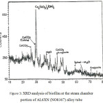 |
Figure 3: XRD analysis of biofilm at the steam chamber portion of AL6XN (NO8367) alloy tube. |
The corrosion deposit consists of many phases of which Fe2O3, (Fe3O4) Fe (CrO4) OH and amorphous materials are the major ones. Different phases were also present in the tube’s steam chamber portion biofilm of which the major phases are Ca3[SiO3(OH)]2.2H2O, calcite and aragonite – CaCO3, spinel – MgO – like structure material and very small amount of biofilm and amorphous materials.
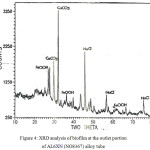 |
Figure 4: XRD analysis of biofilm at the outlet portion of AL6XN (NO8367) alloy tube. |
The overall results obtained, suggest that all the alloys are relatively corrosion resistant under some particular testing conditions. However, there were some situations where strong adherent calcareous layer deposit occurred that led to under deposit corrosion in the steam chamber portion of all the steel tubes tested, though to varying magnitudes.
The corrosion attack resistance of all the alloys in the seawater environment was attributable to the very high alloying contents of the steels – particularly the Mo, Cr, Ni, and to some extent, Si, and Mn. These metallic elements are known43-44 to provide stable passivity for the corrosion resistance of these alloys in corroding media. The slight differences observed, however, in the magnitude of their corrosion resistance, could be associated with the influence of their variable metallurgical compositions and/or their surface finishing characteristics.
It is observed in this work/report that substantial crevice corrosion attack occurred in the steam chamber portion of the tubes when there was strong adherent calcareous layer deposit. The situation that has made the calcareous deposit possible is difficult to explain precisely as this phenomenon was observed only in a test run. An attempt to reproduce the strong adherent and slightly thick calcareous deposit in the metals’ surface did not succeed. This might be due to unavoidable irregularity and anomaly of some inconsistent stoppages caused by power failures among others during the tests.
Operating anomaly such as stoppages, in the steam chamber operating conditions could affect the non-uniformity of results, particularly with respect to calcareous deposition. The operating conditions of the test rig and the elevated temperature at the steam chamber portion of the tubes could disturb the balance between the calcareous compounds and CO2 in the seawater used. A situation as this is known to promote abnormal deposition of calcium carbonate on metal surfaces.7 The high wall temperature (of the steam chamber) could cause the strong adherence of the deposit to the tube metal surface. The high steam operating temperatures was a major cause in further precipitation of CaCO3, MgCO3 and Mg(OH)2, etc. in the seawater flowing through the steam chamber.2 The solubility of these compounds decreases as the temperature increases –particularly the latter two compounds due to the free magnesium ion in the sea water and the predominant stable phase of aragonite at the elevated temperatures.2,7 Lin and Dexter7 agreed that magnesium inhibits nucleation but not crystal growth of aragonite.
The test runs were performed during different periods of the year, that is, over different seasons. The seasonal variation could influence amounts of dissolved ions/ sulphate species.45 Increase in pH of the seawater is a major factor in calcareous layers deposition.1,3,4,5,9 Calcium compounds and CO2 balance of the seawater is not only disturbed with the high steam chamber temperature. It also caused oxygen depletion within the steam chamber. The latter phenomenon would cause less passivity to the steel alloys and also increase the seawater alkalinity and pH which in consequence enhance calcareous deposition of calcite and aragonite – CaCO3.
Apparently, the condition under the calcareous deposit (layer) would be that of severe oxygen (O2) depletion and increased alkalinity – pH at the tube metal – seawater interface. When these are combined with other factors such as high chloride ions, carbonate and sulphate ions from seawater, there will be depassivation of tube metal surface anodic dissolution under the deposits. The corrosion reaction kinetics was thus definitely aided by the used steam chamber elevated temperature.
It can be mechanistically expressed that the overall corrosion process must be that of synergism among the various factors involved; crevice conditions must be available for any reasonable crevice corrosion attack to occur.
The tube(s) surface biofilm enrichment at the different areas of the tube was confirmed with EDAX spectroscopic analysis (Figs 5 – 7) as consisting of different chemical elements such as Ca, Mg, Cl, P and Si. The particular effect of these elements on the biofilm structure and properties, corrosion characteristics and hence the corrosion resistance of the tube alloys is not very clear. Chloride ions, however, could significantly affect the metal alloys passivity – stability of the protective film. The elements – Cr, Ni, Mo, Mg, and Si will more give beneficial effects of stabilizing the alloys’ protective film and also preventing the biofilm’s growth that could cause increased corrosion tendency.
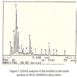 |
Figure 5: EDAX analysis of the biofilm in the outlet portion of 904L (NO8904) alloy tubes. Click here to View figure |
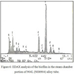 |
Figure 6: EDAX analysis of the biofilm in the steam chamber portion of 904L (NO8904) alloy tube. |
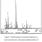 |
Figure 7: EDAX analysis of corrosion deposit at a local corrosion site in the steam chamber portion of AL6XN (NO88367) alloy tube. |
Further analysis with the X-ray diffraction confirms the more enrichment of the biofilm in the steam chamber with Fe, Ca, and Mg than the outlet tube metal biofilm. The presence of CaCO3 – calcite and aragonite was further confirmed as the major composition of the calcareous layer deposited on the metal’s surface. This provides suitable condition for corrosion attack.
All the alloys were susceptible to crevice corrosion attack in seawater environment, particularly, at elevated temperatures but at varying degrees. Any condition that create crevice environment during the use of these super austenitic stainless steel (in seawater) must be avoided. Alloys 254 SMO (S31254) and 1925 HMO (N08925) showed superior corrosion resistance relatively.
Calcium carbonate (CaCO3), MgCO3, sulphates and hydroxides form the major constituents of the calcareous deposition and created crevice condition(s) on the metal surface for crevice corrosion attack. Calcareous deposit is definitely not good for these alloys in seawater – particularly under high temperature use.
The results and observations in this section are largely in agreement with the work of other many researchers working in diverse but related laboratory investigations as reviewed above.46-52
Conclusions
From the various reviewed research reports/articles and an experimental and field work, there is apparent conclusive agreement on seawater’s complexity which in turn showed that:
Crevice conditions existing under the calcareous deposit causes crevice corrosion attack especially in super austenitic stainless steels in seawater.
Calcareous layer deposition consists of CaCO3, MgCO3, Mg (OH)2.
Calcareous formation is influenced by temperature, pH, magnesium ion content level, salinity, potential, current, pressure, seawater chemistry, flow rate.
Calcareous deposits which consist principally of CaCO3; MgCO3 and Mg (OH)2, are solid products that promote a physical barrier against oxygen diffusion.
Cathodic protection of metallic infrastructures in the sea/ocean causes significantly calcareous formation/deposit which in turn serves as protective barrier to the corrosive degradation of the structures.
Dissolution of calcareous deposits is affected by the depth of the sea. The deeper the sea levels the more the calcareous dissolution.
Acknowledgement
The author acknowledges Prof. Ives’ Corrosion Laboratory, McMaster University, Hamilton, Ontario, Canada, where a Laboratory and Field work of a part of this review was performed.
References
- Humble, R.A. Corrosion 1948, 4 (7), 358–379.
CrossRef - Lin, S.H.; Dexter, S.C. Corrosion 1988, 44(9), 615-622.
CrossRef - Gartland, P.O.; Bardal, E.; Andresen, R.E.; Johnsen, R. Corrosion 1984, 40(3), 127-133.
CrossRef - Zeller, E.J.; Wray, J.L. Bull Amer Assoc Petr Geo 1956, 40(1), 140-152.
- Wolfson, S.L.; Hartt, W.H. Corrosion 1981, 37(2), 70-76.
CrossRef - Ellis, A.J. Amer. J. of Sci. 1963, 261, 259-267.
CrossRef - Laque, F. Marine Corrosion, Environmental factors in corrosion of in seawater and sea air; In: Marine Corrosion, NY Wiley & Sons, pp. 105-111 & p.133, 1975.
- Redfield, A.C. Characteristics of Seawater, In: Corrosion Handbook, HH Uhlig (Editor), Wiley NY pp. 1119, 1948.
- Compton, K.G. Proc. Int. Corrosion Forum, Toronto, NACE Paper 13, 1975.
- Principal constituents of seawater, www. Britannica.com.htm.: Retrieved: 02/11/2016.
- Lee, C.; Bae, I.; Kim, K.; Moon, K.M.; Lee, M.H. J. Korean Inst. Surf. Eng. 2004, 37 (5), 253-262.
- Yang, Y.; Scantlebury, J.D.; Koroleva, E.V. Metals 2015, 5 (1), 439-456.
CrossRef - Luo, J.S.; Lee, R.U.; Chen, T.Y.; Hartt, W.H.; Smith, S.W. Corrosion 1991, 47, 189–196.
CrossRef - Li, C.; Du, M.; Qiu, J.; Zhang, J. Acta Metall. Sin. 2014, 24, 131–139.
CrossRef - Barchiche, C.; Deslouis, C.; Gil, O.; Refait, P.; Tribollet, B. Electrochim. Acta 2004, 49, 2833–2839.
CrossRef - Barchiche, C.; Deslouis, C.; Gil, O.; Joiret, S.; Refait, P.; Tribollet, B. Electrochim. Acta 2009, 54, 3580–3588.
CrossRef - Zakowski, K.; Szocinski, M.; Narozny, M. Anti-Corros. Methods Mater. 2013, 60, 95–99.
CrossRef - Refait, P.; Jeannin, M.; Sabot, R.; Antony, H.; Pineau, S. Corros. Sci. 2013, 71, 32–36. 19.Refait, P.; Jeannin, M.; Sabot, R.; Antony, H.; Pineau, S. Corros. Sci. 2015, 90, 375 – 382.
CrossRef - Hartt, W.H.; Culberson, C.H.; Smith, S.H/ CORROSION 83/Paper No. 59, 1983, NACE, Houston, Texas.
- Berner, R.A. Amer. J. Sci. 1976, 271 (6), 713-730.
CrossRef - Li, Y.H.l Takahashi, T.; Broecker, W.S. J. Geophys. Res. 1969, 74, 5507-5525.
CrossRef - Edmond, J.M.; Gieskes, T.M. Geochim. Cosmochim. Acta. 1970, 34, 1261–1291.
CrossRef
- Morse, J.W.; Kanel, J de; Craig, Jr. H.L. Ocean Eng. 1979, 6, 297-315.
CrossRef - Berner, R.A. Principles of Chemical Sedimentology, 1971, p.240, McGraw-Hill, New York, NY.
- Wollast, R. Kinetics aspect of the nucleation and growth of calcite from aqueous solutions, In: Carbonate Cements, Edited by O.P. Bricker, 1971, 264-273, John Hopkins Press, Baltimore.
- Pytkowicz, R.M. J. Geol. 1965, 273, 196-199.
CrossRef - Pytkowicz, R.M. Am. J. Sci. 1973, 273, 515- 522
CrossRef - Kinsman, D.J.J.; Holland, H.D. Geochimica et Cosmochimica Acta 1969, 33, 1-18
CrossRef - Berner, R.A. Geochimica et Cosmochimica Acta 1975, 39 (4), 489-504.
CrossRef - Bischoff, J.L. J. Geophys. Resch. 1968, 73 (10), 3315-3322.
CrossRef - Garrels, M.; Thompson, M.E. Am. J. Sci. 1962, 26, 57– 66
CrossRef - Reddy, M.M.; Nancollas, G.H. J Collo Interf Sci 1971, 36,166–172
CrossRef
- Nancollas, G.H.; Reddy, M.M. J. Coll. Interfac. Sci. 1971, 37, 824-830
CrossRef - Nancollas, G.H.; Reddy, M.M. J. Soc. Petrol Eng. 1974, 14, 117-126.
CrossRef - Weyl, P.K. The solution behaviour of carbonate materials in sea water. Int. Conf. Trop. Oceanog. Proc. 1965, 175-228, Miami Beach, Florida
- Chave, K.E. Science 1965, 148, 1723-1724.
CrossRef
- Chave, K.E.; Suess, E. Trans., N.Y. Acad. Sci. ser II 1967, 29, 991-1000.
CrossRef - Chave, K.E.; Suess, E. Limnol. Oceanogr 1970, 15, 633-637.
CrossRef - Berner, R.A.; Weestrich, J.T.; Graber, R.; Smith, J.R.; Martens, C.S. Am. J. Sci., 1978, 78, 816-837
CrossRef - Reddy, M.M.; Nancollas, G.H. Desalination, 1973, 12, 61–73.
CrossRef - Loto, C.A.; Ives, M.B. NSE Tech. Trans. 1994, 29 (1), 1 – 9.
- Brandy, R.; Van Rooyen, D. Corrosion 1983, 39 (6), 227-236.
CrossRef - Sedriks, A.J. Inter Metals Revs 1983, 28, 295-307.
- Heidersbach, R.H. Marine Corrosion, Metals Handbook. 1984, pp.894, ASM Int. Ninth Ed.
- Eashwar, M.; Subramanian, G.; Palanichamy, S.; Rajagopal, G.’ Madhu, S.; Kamaraj, P. Biofouling 2009, 25(3), 191-201.
CrossRef - Mohammad, Z.; Taghi S.; Ali, Y. Anti-Corros. Methods and Matls 2007, 54(2), 74-81.
- Gabrielli, C.; Maurin, G.; Poindessous, G.; Rosset, R..J. of Crystal Growth 1999, 200 (1-2), 236-250.
CrossRef - Chengjie, L.; Min, D.; Jing, Q.; Jing, Z.; Congjie, G. Acta Metallurgica Sinica (English Letters) 2014, 27(1), 131-139.
CrossRef - Salvago, G.; Maffi, S.; Benedetti, A.; Magagnin, L. Electrochimica Acta 2004, 50(1), 169-178.
CrossRef - Deslouis, C.; Festy, D.; Gil, O. Electrochim. Acta 1998, 43, 1891–1901.
CrossRef - Barchiche, C.; Deslouis, C.; Festy, D.; Gil, O.; Refait, P.; Touzain, S.; Tribollet, B. Electrochim Acta 2003, 48, 1645–1654.
CrossRef

This work is licensed under a Creative Commons Attribution 4.0 International License.
![]()
A New Edition of Web of Science
Journal Impact Factor
2022: 0.5
Five Year: 0.8
Journal is Indexed in

Cabells Whitelist
![]()


