Method for Introducing Non-Metallic Particles Into Composite Coatings
M.S. Sataev , Sh.T. Koshkarbayeva, N. K. Sarypbekova, G. S. Kenzhibayeva, G. A. Kambarova and A. Zh. Suigenbayeva
M. Auezov South Kazakhstan State University, Shymkent, Kazakhstan.
Corresponding Author E-mail: malik_1943@mail.ru
DOI : http://dx.doi.org/10.13005/ojc/340316
Article Received on : March 31, 2018
Article Accepted on : May 02, 2018
Article Published : 04 Jun 2018
A method for producing composite coatings is proposed, in which initially a layer of non-metallic phase is created on the surface to be coated. For this, the product is wetted with a solution of copper sulfate, then a non-metallic phase is sprayed onto this layer. When the product is subsequently processed with phosphine, a primary metallic layer is formed, which fixes the non-metallic phase on the surface of the article. Further overgrowth by the metal phase (matrix) by galvanic or chemical means. The method allows to introduce up to 40% non-metallic phase.
KEYWORDS:Composite Coatings; Copper Phosphide; Graphite; Powders; Titanium Dioxide
Download this article as:| Copy the following to cite this article: Sataev M. S, Koshkarbayeva S. T, Sarypbekova N. K, Kenzhibayeva G. S, Kambarova G. A, Suigenbayeva A. Z. Method for Introducing Non-Metallic Particles Into Composite Coatings. Orient J Chem 2018;34(3). |
| Copy the following to cite this URL: Sataev M. S, Koshkarbayeva S. T, Sarypbekova N. K, Kenzhibayeva G. S, Kambarova G. A, Suigenbayeva A. Z. Method for Introducing Non-Metallic Particles Into Composite Coatings. Orient J Chem 2018;34(3). Available from: http://www.orientjchem.org/?p=46454 |
Introduction
The development of many branches of modern technology largely depends on the development and practical use of different types and types of metal coatings. Promising is the use of composite coatings (СС) that contain non-metallic inclusions along with the main metallic phase, which give the products new functional properties inherent in the components of the coating (heat resistance, chemical resistance, high hardness), as well as completely new properties such as amorphous structure, catalytic activity, photosensitivity, etc.1-3
The main methods for obtaining such composite films are galvanic deposition of metals or alloys from electrolytes containing suspensions of nonmetallic particles.
The formation of the СС is based on the rotation into the cathode-evolving metal of particles of the second phase with a size from 1-10 nm to several micrometers. This process depends not only on the conditions of electrolysis: temperature, mixing, but also on the dispersity, nature and number of particles. The possibility of their use for the preparation of CС is determined by their physicochemical properties. First of all, this is the size, shape and ability to acquire a positive charge. 4,5 The smaller the size and the more distorted the crystal lattice of particles, the easier they are captured by irregularities in the surface of the metal. By acquiring a positive charge, dispersed particles move faster to the cathode and are easier to integrate into the coating.
In this case, the particles of this phase, when the solution of the electrolyte is stirred mechanically, fall on the surface of the article and become infected with the precipitation of the base metal. Although the main provisions of technology were developed back in the last century,4,5 interest in this method has not yet been extinguished. This was promoted by scientific achievements of recent years in the field of nanotechnology, chemical sources of current, catalysts, etc. So at present the object of large-scale research has become nanocomponent coatings,
Among the parameters that positively influence the amount of particles included, there is a high concentration of nanoparticles in the electrolyte solution, a decrease in particle sizes. Mixing, ultrasonic treatment and the use of impulse current also have a positive influence.1,2
To increase the anticorrosive and tribological properties, the efficiency of introduction of aluminum oxide into nickel coatings is shown.6 In,7 corrosion inhibitors of magnesium alloys are proposed to incorporate inhibitors into the coating composition. The results obtained show that the protective properties of such coatings are higher than those obtained by plasma electrochemical oxidation. The composite material consisting of polyaniline and graphite of a vein graphite needle is suitable as a protective coating for steel surfaces.8
The nickel-reduced composite coating of graphene oxide exhibited high electrocatalytic activity for the hydrogen evolution reaction9
There are some other methods for obtaining composite coatings, but they are small-scale and solve individual problems. Thus, chemical vapor deposition of thin films of photocatalytic titanium dioxide into which synthetic hydroxyapatite [Ca10 (PO4) (OH)2 ] was added during the synthesis of the dioxide was described. Tests of photocatalytic activity showed that the inclusion of hydroxyapatite in composite films increases their effectiveness. [10] The development of a composite coating for magnesium from a conductive polymer of 3,4-ethylenedioxythifene and graphene oxide11 is also reported. In this case, the composite coating was obtained on Mg samples by electropolymerization in an ethanol medium. Increasing the corrosion resistance makes it promising to use medical implants based on Mg. A strong antimicrobial coating was also made by incorporating the TiO2 / Ag composite in an emulsion solution of polyvinyl acetate.12
The use of electrolyte-suspension requires constant mixing, which complicates the design of galvanic baths and often disrupts the stability of the electrolyte solution. In addition, the content of the second (non-metallic) phase in the composite coatings in some cases does not exceed a few percent.3,4 There are difficulties when large particles are included in the cathode sediment. At the same time, there is also no possibility of applying composites on non-conductive surfaces.
Therefore, there is a need to develop alternative technologies that make it possible to obtain coatings of the desired composition with higher contents of the second component and enabling the use of standard galvanic and chemical processes for building matrix metal.
Materials and Methods
Materials
In the research, powdered graphite grade C-1 TU 113-08-48-63-90 (Russia) and titanium oxide (IV) of the grade “osch” 7-3 TU 6-09-3811-39 (Russia) were used. Separate stages of the process were studied with the ISM-6490-LV (IEOL, Japan) scanning electron microscope, which makes it possible to obtain an electronic image of the surface and the elemental composition of the surface layers.
Method for obtaining a composite coating
The low-temperature method developed by the authors for depositing electrically conducting films on metallic and dielectric materials13-15 assumes the use of gaseous phosphine as a reducing agent.
In this technology there is an intermediate stage of creating a sorption layer on the surface of the product by wetting with an aqueous solution of copper sulfate. We propose at this stage to spray on the wetted surface of the product particles of the second phase. In this case, the particles will be temporarily retained by the surface tension of the aqueous solution. Later they will be fixed with a layer of solid copper phosphide formed.
With this in mind, a somewhat modified technology for obtaining a composite coating will consist of the following main stages:
Preliminary surface preparation;
Creation of a surface layer of copper sulfate solution;
Sputtering of the non-metallic phase;
Treatment with gaseous phosphine;
Additional galvanic or chemical metallization;
Grinding or polishing.
The diagram of the basic operations is shown in Figure 1.
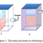 |
Figure 1: The main processes in obtaining СС |
1 – creation of sorption layer of CuSO4 solution; 2 – deposition of the second phase; 3 – fixing the second phase; 4 – preparation of the component for applying the layer of the matrix.
The resulting changes in the surface of the product are shown in Figure 2.
The preparation of the sample surface is carried out to remove the oxide films and to create wettability. For this, methods commonly used in galvanic engineering are used [3]. In this paper, the preparation of copper samples was carried out by stripping with abrasive paper, degreasing and etching in nitric acid (Fig. 2, a).
The surface layer of the copper sulfate solution is created by dipping the samples for 3-5 seconds in a solution containing 300 g / L copper sulfate. After removing the sample from the solution, the removal of the solution due to the adhesion forces is 100-120 ml / m2, which ensures the creation of a 50-70 μm solution layer on the sample surface (Fig. 2, a). The concentration of copper sulphate 300 g / L ensures further formation of a copper phosphide layer sufficient to retain the second phase. At higher concentrations, the formation of formless surface crystals of copper sulfate is enhanced.
After creating a film of copper sulfate solution, the sample is shaken to remove the inflow of solution in separate areas. Then, the non-metallic phase is sprayed onto this wet layer. Sputtering was carried out in a cylindrical vessel having a diameter of 10 cm and a height of 40 cm (Fig. 3). The sprayed powder is covered in the lower part of the vessel, and the sample is hung on the lid, which hermetically sealed the top of the cylinder. Compressed air was supplied through the opening in the lower part of the cylinder. In this case, the particles of the second phase rise to the upper part of the cylinder and adhere to the wet surface of the sample. The time of spraying does not exceed 20-30 seconds. To compensate for excess pressure, the cylinder cover has an opening to which a rubber ball was attached. As a result of the deposition, the surface layer was filled with particles of the second phase (Fig. 2, c). At the same time, some particles may not be completely covered by the electrolyte solution.
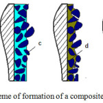 |
Figure 2: Scheme of formation of a composite coating. |
A is a separate section of the initial surface of the sample; b – surface layer of copper sulfate solution with a thickness of 50-70 μm; c – surface layer filled with particles of the second phase; d – surface layer after transformation of copper sulfate solution into solid copper phosphide; e – surface layer after application of additional metal; f-. surface layer with an aligned composite coating.
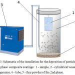 |
Figure 3: Schematic of the installation for the deposition of particles of the second phase composite coatings: 1-sample, 2 – cylindrical vessel, 3 – compressor, 4 – tube, 5 – fine powder of the 2nd phase. Click here to View figure |
Treatment with gaseous phosphine is carried out for the reduction of copper ions. In this case, the liquid sorption layer of the copper sulfate solution is transformed into a solid metal-like copper phosphide in which the particles of the nonmetallic phase are distributed. The process is carried out in a sealed chamber. After placing the sample, the chamber is purged with nitrogen to remove air and then phosphine is fed into the chamber. As a result of the reaction.
6 CuSO4+3PH3+3H2O→2Cu3P +6H2SO4+H3PO3 (1)
Phosphine is absorbed to form copper phosphide. The film is dark gray color has a pronounced metallic properties, has a metallic shine and conducts an electric current well. The electrical conductivity of the coatings, determined by measuring the resistance of the coating by the direct current method, was 359÷400×10-6 Ом-1×м-1[13]. The film thickness is about 0.5 μm in the absence of the deposited non-metallic phase. When the non-metallic particles are sprayed, its thickness can increase considerably. After washing the reaction by-products, the film is a layer of solid copper phosphide with embedded non-metallic phase particles (Figure 2, d).
It is seen from this figure that some particles of the second phase are only partially bound by solid copper phosphide, so it is recommended to apply an additional layer of the metal phase completely covering these particles (Fig. 2, e). For this, standard galvanic or chemical methods for depositing metals can be used.
If necessary, the surface of the coating can be aligned by grinding or polishing (Figure 2, f).
Results and Discussion
This process was tested to obtain composite coatings by introducing into the metal matrix particles of graphite and titanium dioxide. Earlier, the possibility of introducing diamond particles into a copper coating was demonstrated .16
The results of the experiments are given in Table 1. From these data it can be seen that the number of particles of the dielectric phase sputtered onto the wet surface of the part, and then fixed with copper phosphide, remained unchanged in the CС.
Table 1: Changes in the mass of the sample after the operation to apply the non-metallic phase.
|
Name of operation |
Non-metallic phase to be introduced |
|||
|
Graphite |
Titanium Dioxide |
|||
|
Weight, g |
Weight, g |
Weight, g |
Weight, g |
|
|
The initial sample S=50см2 |
4,554 |
– |
4,522 |
– |
|
Treatment with copper sulphate |
4,836 |
0,282 |
4,800 |
0,278 |
|
Sputtering of the second phase |
5,357 |
0,496 |
5,412 |
0,589 |
|
The formation of a copper phosphide layer |
5,092 |
-0,278 |
5,151 |
-0,261 |
|
Coating (copper) |
5,966 |
0,874 |
6,022 |
0,871 |
|
Content of the second non-metallic phase |
35 |
40 |
Figure 4 shows the electronic image of the graphite-containing composite coating after fixing with copper phosphide (3, a) and after applying an additional layer of plated copper (3, b). In order to reveal the structure, part of the surface layer of copper is removed by grinding.
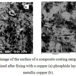 |
Figure 4: Electronic image of the surface of a composite coating sample with a nonmetallic graphite phase, obtained after fixing with a copper (a) phosphide layer and after applying metallic copper (b). |
Both copper and graphite phases are clearly marked in the photo. The elemental composition showed that the dark areas correspond to metallic copper, the lighter graphite.
In the preparation of a composite coating containing, as a non-metallic phase, titanium dioxide, also a certain portion of the spherical TiO particles having a diameter of 20-50 μm is only partially covered with an electroconductive layer of copper phosphide (Fig. 5, a).
Since titanium dioxide does not have electrical conductivity, their outer surface remains clean. These areas during the subsequent application of the copper plating layer will not be sufficiently associated with the matrix due to the absence of an electrically conductive layer. Therefore, in order to enhance the bond between these particles and the matrix, it is recommended that the copper phosphide layer be re-applied. After this, as seen from Fig. 5b, a dense overgrowth of the nonmetallic phase is achieved, which leads to an improvement in the mechanical properties of the obtained CC.
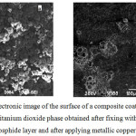 |
Figure 5: Electronic image of the surface of a composite coating sample with a nonmetallic titanium dioxide phase obtained after fixing with a copper (a) phosphide layer and after applying metallic copper (b). |
Sufficiently strong adhesion of titanium dioxide particles to each other and to the surface of the sample indicates that the copper sulfate solution penetrates into the micropores of these particles and then forms a single phosphide backbone that holds together nonmetallic particles.
Conclusion
The separate implementation of the process of introducing the non-metallic phase into metal coatings has the following advantages.
Allows to receive coatings with increased content (up to 40%) regardless of the physico-chemical properties of the second phase. Also, the proposed method makes it possible to obtain CP with relatively large (up to 50 μm) particles of the nonmetallic phase.
The range of substances used as the second phase is expanded, since the restriction on the delivery of these substances to the surface of the cathode is removed. At the same time, the method makes it possible to obtain composite coatings on standard apparatus used in galvanic engineering.
References
- Low, C.T.J., Wills, R.G.A., Walsh, F.C. Surf Coat Tech, 2006, 201(1-2), 371-383.
- Kavian O. Cooke (March 23rd 2016). Parametric Analysis of Electrodeposited Nano-composite Coatings for Abrasive Wear Resistance. In book Electrodeposition of Composite Materials A.M.A Mohamed, IntechOpen, DOI: 10.5772/62153.
CrossRef - Nowak, M., Najder, A., Opyrchał, M., Boczkal, S., Żelechowski, J., Bigaj, M., Gawlik, M. Archives of Metallurgy and Materials, 2016, 61(1), 195-198.
- Gnedenkov, A.S., Sinebryukhov, S.L., Mashtalyar, D.V., Gnedenkov, S.V. Corros Sci., 2016, 102, 348-354.
- Rathnayake, R.M.N.M., Mantilaka, M.M.M.G.P.G., Hara, M., Hsin-Hui Huang., Wijayasinghe, H.W.M.A.C., Yoshimura, M., Pitawala, H.M.T.G.A. Appl Surf Sci., 2017, 410, 445-453.
- Jinlong, L., Tongxiang, L., Chen, W. Appl Surf Sci, 2016, 366, 353-358.
- Piccirillo, C., Denis, C.J., Pullar, R.C., Binions, R., Parkin, I.P., Darr, J.A., Castro, P.M.L. J Photochem Photobiol A Chem, 2017, 332, 45-53.
- Catt, K., Li, H., Tracy Cui, X. Acta Biomaterialia, 2017, 48, 530-540.
- Ye, J., Cheng, H., Li, H., Yang, Y., Zhang, S., Rauf, A., Zhao, Q., Ning, G. J Colloid Interface Sci, 2017, 504, 448-456.
- Koshkarbaeva, Sh. T., Nauryzova, S.Z., Sataev, M.S., Tleuova, A.B. Orient J Chem, 2012, 28(3), 1281-1283.
- Sataev, M.S., Abdurasova, P.A., Koshkarbaeva, Sh.T., Bolisbek, A.A., Saripbekova, N.K., Kambarova, G.A., Koblanova, O.N., Perni, S., Prokopovich, P. Colloids Surf A Physicochem Eng Asp, 2017, 521, 86-91
- Sataev, M.S., Koshkarbaeva, Sh.T., Tasboltaeva, A.B. Izvestiya vuzov. Tekhnologiya tekstilnoy promyshlennosti, 2013, 6 (348), 102-104.
- Sayfullin R.S., Fomina R.Ye., Mingazova G.G., Vodopyanova S.V., Grigoryeva I.O., Ksenofontova R.K. Vestnik Kazanskogo tekhnologicheskogo universiteta. 2010, 11, 358-363.
- Vodopyanova S.V., Fomina R.Ye., Mingazova G.G., Sayfullin R.S., Gafurova D.F., Vestnik Kazanskogo tekhnologicheskogo universiteta. 2010, 10, 66-73
- Tseluykin V.N. Elektroosazhdeniye i svoystva kompozitsionnykh pokrytiy nikel’-grafit. Perspektivnye materialy. 2009. №2. 85-87
- Sataev, M.S., Koshkarbaeva, Sh.T., Perni, S., Nauryzova, S.Z., Prokopovich, P. Colloids Surf A Physicochem Eng Asp, 2015, 480, 384–389.

This work is licensed under a Creative Commons Attribution 4.0 International License.
![]()
A New Edition of Web of Science
Journal Impact Factor
2022: 0.5
Five Year: 0.8
Journal is Indexed in

Cabells Whitelist
![]()


