Chemical Composition of Liquid Fuel Produced by Co-pyrolysis of Sugarcane Bagasse and Sludge Palm Oil Using Zeolite-Yas Catalyst
Raden Supriyanto , Wasinton Simanjuntak, Kamisah D. Pandiangan, Rudy T. M. Situmeang and Muhammad Yusry Ahmadhani
Department of Chemistry, The University of Lampung Jalan Prof. Soemantri Brojonegoro No. 1 Bandar Lampung, 35145.
Corresponding Author E-mail: priyanto_5811@yahoo.com
DOI : http://dx.doi.org/10.13005/ojc/340345
Article Received on : March 24, 2018
Article Accepted on : April 19, 2018
Article Published : 01 Jun 2018
In this investigation, co-pyrolysis of sugarcane bagasse and sludge palm oil for production of liquid fuel was investigated. A series of pyrolysis experiments was conducted using zeolite-Y synthesized from rice husk silica and aluminum metal through sol-gel route and calcined at different temperatures as catalyst. The pyrolysis experiments were conducted at fixed temperature of 350oC, and the liquid fuels produced were analyzed using gas chromatography-mass spectrometry (GC-MS) technique for component identification. The results obtained indicate that the main component of the liquid fuels is hydrocarbon, with the highest content of 80% was produced with the use of catalyst calcined at 700oC. Production of liquid fuels with high hydrocarbon content and practically contain no acids demonstrated that catalyst zeolite-Y synthesized exhibited appreciable selectivity toward formation of hydrocarbons, and simultaneously prevent the formation of acids.
KEYWORDS:Bagasse; Co-pyrolysis; Liquid fuel; Sludge palm oil; Zeolite-Y
Download this article as:| Copy the following to cite this article: Supriyanto R, Simanjuntak W, Pandiangan K. D, Situmeang R. T. M, Ahmadhani M. Y. Chemical Composition of Liquid Fuel Produced by Co-pyrolysis of Sugarcane Bagasse and Sludge Palm Oil Using Zeolite-Yas Catalyst. Orient J Chem 2018;34(3) |
| Copy the following to cite this URL: Supriyanto R, Simanjuntak W, Pandiangan K. D, Situmeang R. T. M, Ahmadhani M. Y. Chemical Composition of Liquid Fuel Produced by Co-pyrolysis of Sugarcane Bagasse and Sludge Palm Oil Using Zeolite-Yas Catalyst. Orient J Chem 2018;34(3). Available from: http://www.orientjchem.org/?p=46374 |
Introduction
Palm oil is one of the most rapidly growing plantation crops, especially in topical countries, including Indonesia. This crop is acknowledged to play very important role as an income generating sector with appreciable contribution to the economic benefit of many palm oil producing countries. However, it should be recognized that palm oil industry is also one of the industries which generates very large volume of hard-to-handle wastewater. As an illustration, it was reported that production ofone ton of palm oil requires between 50,000 to 75,000 liters of water.1,2 In the liquid waste contained various components, one of them is the residual oil with a concentrationaround 4000-9000 ppm.1,2 This residual oil is commonly known as sludge palm oil (SPO), and mixed with various other organic materials produced during the production process. In the waste ponds, sludge palm oil is found on the surface and frozen, resulting in very bad impacts on the aquatic ecosystems where the wastewater was released.
As part of the liquid waste treatment of the palm oil industry, several attempts to utilize sludge palm oil have been reported. In previous studies,3,4 utilization of wastewater for biogas generation was reported. However, this process is unable to overcome the problem, since the process was reported to require very long retention time, which is about 20 to 50 days,1 mainly because sludge palm oil is characterized by low pH, very high biological oxygen demand (BOD), and the existence of sludge palm oil as a colloid which inhibits microbiological activity. Furthermore, because of such very slow formation, in practice the resulting biogas is not utilized, but simply released into the atmosphere.
The second attempt that has been reported was conversion of sludge palm oil into biodiesel.5,6. However, this method also suffers from limited success due to two several fundamental drawbacks i.e. the need to purify the sludge palm oil from organic impurities and water, since these components severely limit the transesterification process of vegetable oil, the need for very high of alcohol to oil ratio which ranges from 10: 1 to 20: 1, and much longer reaction time than that required by other raw materials. In addition to the above two methods, several other methods have been investigated, such as membrane filtration,7 composting,2 and utilization as animal feed.8,9
Another potential method for conversion of biomass to valuable products, with particular emphasis on renewable energy source, that has been extensively explored in the last few decades is pyrolysis. Pyrolysis is thermal treatment of large organic molecules without or in the presence of limited oxygen, to crack the molecules into simpler compounds, in the form of gas, liquid, and solid product known as biochar. In the realm of development of renewable energy source, liquid fuel in particular, pyrolysis continuous to attract growing interest since this technique offers several advantages compared to bioethanol and biodiesel production. Unlike the production of bioethanol and biodiesel, which requires specific reactants, pyrolysis technique is applicable to any kind of biomass, therefore no obstacle in term of raw material. In addition, the pyrolysis process is very fast, making it more efficient in term of time, and does not require expensive equipment. With the above advantages, pyrolysis technique has been applied to produce liquid fuels from various raw materials, such as coconut oil and palm oil,10,11 kranji seeds,12 used tires,13 and palm oil empty bunches.14 In practice, pyrolysis is more widely carried out in the presence of catalyst, since this agent has been acknowledged to function not only to accelerate the process but also to determine the type of compound (component) in liquid fuel produced. Various types of catalyst have been reported, and of particular interest are synthetic zeolites.15
It is in the light of the above advantages that this investigation was undertaken to explore the feasibility of pyrolysis to convert the mixture of sludge palm oil and sugarcane bagasse into liquid fuel. These two raw materials were tested considering their existence as less usable agricultural residues abundantly available in Indonesia. A series of pyrolysis experiments were carried out with the use of zeolite-Y synthesized from rice husk silica and aluminum metal as catalyst, with the main objective to study the effect of calcination temperatures of the catalyst on the chemical composition of the liquid fuel produced.
In this study, the use of rice husk silica as a raw material for preparation of the zeolite is based on several reasons. Rice husk is an agroindustry reside abundantly available and can be obtained for practically free of cost. The silica in the form of sol can be obtained with simple alkaline extraction. Neutralization of the sol using acidic agent will convert the sol into gel, which can be dried to produce high purity solid silica. In addition, rice husk silica is known as amorphous and reactive material, making it suitable for production of composite materials, such as zeolite.
Materials And Methods
Materials and Instruments
Reagent grade sodium hydroxide and nitric acid were purchased from Aldrich, aluminum metal rods were purchased from CV Aluminium Jaya Perkasa, Jakarta, and rice husk was kindly supplied by a local rice milling industry in Bandar Lampung. Sugarcane bagasse was obtained from a sugar company and sludge palm oil was kindly supplied by a palm oil company, both in Bandar Lampung. Furnace used for calcination treatment of catalyst is a Nabertherm electrical furnace (Lilienthal, Germany). Pyrolysis experiment was carried out on a laboratory scale pyrolysis unit. For separation and identification of the chemical components, the liquid fuels were analyzed using the GCMS-QP2010 SE SHIMADZU.
Procedure
Silica was extracted from rice husk by alkali extraction method reported in previous study.16 In brief, the extraction procedure involves the mixing of 50 gram dried husk with 500 mL of 1.5% NaOH solution and subsequent boiling of the mixture for 30 min, and finally then left for 24 h at room temperature. The filtrate which contains silica (silica sol) was collected by filtering the mixture, while the residue was discharged. The sol was then acidified by dropwise addition of liquid smoke until the sol was converted into gel. The gel was aged for three days, and then rinsed repeatedly with deionized water to remove the excess of liquid smoke. The gel was oven dried at 110oC for eight hours and ground into powder.
Zeolite-Y was prepared according to the general formula of (Na2O.Al2O3.4.8SiO2.xH2O). Typical sample was prepared by dissolving 20 gram NaOH crystal in 350 mL of distilled water. An aliquot of 100 mL of the NaOH solution was used to dissolve 13.5 gram of Al metal, and the rest (250 mL) was used to dissolve 77 gram of rice husk silica. Both solutions were then thoroughly mixed using a laboratory mixer, and then transferred into a polypropylene bottle. The bottle was then immersed in water bath set up at 85oC for crystallization. The crystallization step was run for 24 hours. After the completion of this crystallization step, the gel was oven dried at 110oC for 24 hours and then ground into powder. Three powder samples were prepared and subjected to different calcination temperatures of 600, 700, and 800oC for six hours.
Before use, sugarcanebagasse wassun-dried, then cut into small pieces and finally ground into fine powder.The frozen sludge palm oil was heated to melt, then while still in liquid state the oil was filtered to remove impurities, such as the crumbs of the plant residue trapped in the frozen oil. To commence the pyrolysis experiment, 100 gram of sludge palm oil and 50 gram of sugarcane bagasse were mixed and left for 24 hours to optimize the mixing of the two raw materials. Into the raw material mixture, 7.5 gramof catalyst was added, and the sample was transfer into pyrolysis unit. Pyrolysis experiment was carried out at fixed temperature of 350oC. The liquid fuel obtained was transferred into separatory funnel for separation of water phase from organic phase (liquid fuel). The two phases were then collected separately and weighted for calculation of the yield. The liquid fuels were then then analyzed by GC-MS, with the aid of MS Library system Wiley 229 for tentative identification of the chemical composition of the liquid fuel.
Result and Discussion
Prior to pyrolysis experiments with the use of catalyst, an experiment without catalyst was carried out as a base to evaluate the effect of catalyst on the composition of the liquid fuel produced. The GC chromatogram of the liquid fuel obtained from the experiment without the use of catalyst is presented in Figure 1. As can be seen in Figure 1, the chromatogram displays the presence of 23 tentatively identified compounds, which is significantly fewer than the number of compounds composing liquid fuels generally reported in literatures.17,18 In addition, the intensities of most of the compounds are considered too low to convince their existence.
Several representative compounds composing the liquid fuel are ethylene glycol (peak 1), n-heptane (peak 3), n-octane (peak 4), ethylbenzene (peak 5), and pentadecane (peak 18). The feature of GC chromatogram of the sample (Figure 1) clearly demonstrates that without the involvement of catalyst, conversion of the raw materials into liquid product was very limited. This limitation is in accordance with considerably low yield (18.6%) of the liquid fuel obtained.
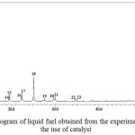 |
Figure 1: GC chromatogram of liquid fuel obtained from the experiment without the use of catalyst |
To evaluate the effect of catalyst on the composition of liquid fuel, the samples obtained with the use of catalysts calcined at different temperatures were analysed. The GC chromatogram of liquid fuel obtained from the experiment with the use of catalyst calcined at 600oC is presented in Figure 2, and the list of identified components is presented in Table 1.
Table 1: Chemical composition of liquid fuel obtained using catalyst calcined at 600oC
|
Peak No |
Retention time (min) |
Compound name |
Molecular formula |
Category |
| 1 | 2.00 | 1,2-Ethanediol | C2H6O2 | Alcohol |
| 2 | 16.27 | 2-Propanone | C3H6O | Ketone |
| 3 | 19.36 | Heptane | C7H16 | Hydrocarbon |
| 4 | 22.23 | 1-Octene | C8H16 | Hydrocarbon |
| 5 | 24.92 | Octane | C8H18 | Hydrocarbon |
| 6 | 34.96 | Ethylbenzene | C8H10 | Hydrocarbon |
| 7 | 46.29 | p-Xylene | C8H10 | Hydrocarbon |
| 8 | 2.84 | 1-Nonene | C9H18 | Hydrocarbon |
| 9 | 3.85 | Nonane | C9H20 | Hydrocarbon |
| 10 | 3.99 | 1-Decene | C10H20 | Hydrocarbon |
| 11 | 5.38 | Decane | C10H22 | Hydrocarbon |
| 12 | 5.60 | 2-Decene | C10H20 | Hydrocarbon |
| 13 | 6.16 | 5-Undecene | C11H22 | Hydrocarbon |
| 14 | 6.42 | Undecane | C11H24 | Hydrocarbon |
| 15 | 9.45 | Cyclopropane | C11H22 | Hydrocarbon |
| 16 | 9.76 | 1-Dodecene | C12H24 | Alcohol |
| 17 | 9.96 | Dodecane | C12H26 | Hydrocarbon |
| 18 | 12.95 | 1-Tridecene | C13H26 | Alcohol |
| 19 | 13.24 | Tridecane | C13H28 | Hydrocarbon |
| 20 | 13.42 | 1-Tetradecanol | C14H30O | Alcohol |
| 21 | 16.54 | Tetradecane | C14H30 | Hydrocarbon |
| 22 | 19.61 | 1-Pentadecene | C15H30 | Alcohol |
| 23 | 22.46 | Pentadecane | C15H32 | Hydrocarbon |
| 24 | 25.18 | Nonadecane | C29H40 | Hydrocarbon |
| 25 | 27.62 | 9-Eicosene | C20H40 | Hydrocarbon |
| 26 | 29.48 | Heneicosane | C21H44 | Hydrocarbon |
| 27 | 29.62 | p-Didecyl | C26H46 | Hydrocarbon |
| 28 | 30.01 | 2-Heptadecanone | C17H34O | Ketone |
| 29 | 34.49 | Methyl palmitate | C17H34O2 | Ester |
| 30 | 2.11 | 2-Pentadecanone | C18H36O | Ketone |
| 31 | 38.55 | 5-Octadecanone | C18H36O | Ketone |
| 32 | 41.76 | 8-Octadecanone | C18H36O | Ketone |
| 33 | 43.49 | 10-Nonadecanone | C19H38O | Ketone |
| 34 | 45.16 | bis (2-ethylhexyl) phthalate | C24H38O4 | Ester |
Comparing the chromatograms (Figure 1 and Figure 2), very obvious differences can be seen, both in term of the number of compounds composing the samples and the intensities of the peaks exist in the chromatogram. As can be seen, as many as 34 compounds were identified in the liquid fuel produced from the experiment with the use of catalyst (Figure 2), which is very significanly larger than the number of compounds composing the liquid fuel produced without the use of catalyst (Figure 1). In term of peak intensity, it can be seen that the intensities of peaks in the GC chromatogram of the sample obtained with the use of catalyst are significantly higher than those of the peaks observed in the chromatogram of the sample produced without catalyst. These different characteristics suggest that in the presence of catalyst, the pyrolysis process led to more intensive fragmentation of the raw material molecules into liquid products. This enhanced process is evidently indicated by increased number of the compounds identified, as well as the intensities of the peaks in the chromatogram of the sample produced with the use of catalyst. In overall, the results obtained signify the importance role of catalyst to enhace the formation of liquid product during pyrolysis process.
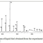 |
Figure 2: GC chromatogram of liquid fuel obtained from the experiment using the catalyst calcined at 600oC |
In general, it is acknowledged that pyrolysis treatment of biomass involves very complicated reactions, however, the exact mechanisms have not been fully understood up to this present time. These complicated reactions during the pyrolysis process lead to formation of varied fragment compounds composing liquid fuel produced. In addition, the chemical composition of liquid fuel obtained from pyrolysis of biomass is also determined by the types of raw materials, the catalyst used, and the experimental conditions applied.Since liquid fuel obtained by pyrolyis of biomass is generally composed of an array of organic compounds, it is very difficult to compare the compositions of different samples based on a single compound. In practice, the identified components are grouped into several more general categories of organic compounds, thus simplifying the comparison between samples.
As shown in Table 1, the components of the liquid fuel were assigned to four categories, i.e. hydrocarbon, alcohol, ester, and ketone. Assignment of chemical components composing liquid fuel obtained by pyrolysis of biomass has also been reported by others, such as allocation of the components into acids, oxygenates, phenolics, aliphatic hydrocarbons, monocyclic aromatics, polycyclic aromatics, and nitrogen-containing species,18 and into five categories of hydrocarbon, aromatics, phenolics, alcohol, and other oxygenates,19 By grouping the components into wider categories, the relative composition of the liquid fuel can be expressed in simpler feature, such as using bar chart indicated in Figure 3.
As can be seen in Figure 3, the main component of the liquid fuel is hydrocarbon which contributes 76% to the composition. From practical point of view, the existence of hydrocarbons as the prime component is advantageous since this class of compound is considered as the ideal fuel. The presence of hydrocarbon as the dominant component suggests that the developed catalyst possesses considerably high selectivity toward hydrocarbon formation during the pyrolysis process.
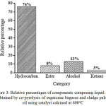 |
Figure 3: Relative percentages of components composing liquid fuel obtained by co-pyrolysis of sugarcane bagasse and sludge palm oil using catalyst calcined at 600oC |
Another interesting feature associated with the composition of the liquid fuel is the absence of acid. The absence of this category is very advantageous,since acids are considered as the most undesirable components due to their toxicity and corrosive nature. Apart from these advantageous compositional features, the presence of less desirable oxygenated components (alcohol, ester, and ketone) should be taken into account. In this respect, the need for upgrading process should be acknowledged, before the liquid fuel could be used in practical utilization.
To further investigate whether the calcination temperatures impart significant effect on the chemical composition of liquid fuel, pyrolysis experiments were also carried out using the catalysts calcined at 700 and 800oC. The GC-chromatograms and bar charts presenting the relative composition of the fuels obtained are compiled in Figure 4. Comparing the chromatograms of the liquid fuels obtained with the use of catalysts (Figure 3 and Figure 4), it can be seen that in general the three chromatograms are very similar, suggesting that the three samples are composed of mostly the same chemical compounds. The similarity of the samples is also displayed by the existence of hydrocarbon category as the main component of the three samples. In addition, it can be seen that the liquid fuel with the highest relative percentage of hydrocarbon (80%) was obtained with the use of catalyst calcined at 700oC, and then decreases to 69% with the use of catalyst calcined at 800oC. The change in relative compositions of the samples, primarily the change in hydrocarbon contents, suggest that to certain extent, the calcination temperatures of catalyst influence the pyrolysis process.
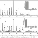 |
Figure 4: GC chromatogram and relative composition of liquid fuel obtained from the experiment using the catalyst calcined at 700oC (a) and the catalyst calcined at 800oC (b) |
Another difference between the samples is the existence of aldehyde in the liquid fuel produced by the use of catalyst calcined at 800oC, while in the liquid fuels obtained using the other two catalysts, this category is undetected. Acknowledging the highest hydrocarbon content and the absence of acid, it was then concluded that the liquid fuel produced with the use of catalyst calcined at 700oC as the most potential liquid fuel for further study.
The variation in the compositions has been acknowledged as a common feature of liquid fuels obtained from pyrolysis of different raw materials. As an example, the existence of hydrocarbon as the prime component of liquid fuel, with the relative percentage of 86%, was also reported in a previous study.17 In the study, co-pyrolysis of sugarcane bagasse and rubber seed oil was conducted using aluminosilicates with different Si/Al ratios as catalysts, and the catalyst with the Si/Al of 9.6 was found to result in liquid fuel with the highest hydrocarbon content. In another study,19 pyrolysis of Nafier grass using ZSM-5, HZSM-5, and zinc exchanged zeolite-A was carried out and it was reported that hydrocarbon content of the liquid fuels is in the range of 25-30%. The existence of non-hydrocarbon as the main component, include acid, phenol, and aldehyde, has also been reported by other.20 Other workers21 also reported the presence of acids, ketones, phenols, and furans, as the dominating components of liquid fuels obtained by pyrolysis of white oak and sweet gum without using catalyst.
In addition to chemical composition, another aspect of biomass pyrolysis commonly reported is the yield. In this current study, the yield of liquid fuel is in the range of 18.6 – 37.4 wt.%. This range of liquid fuel yield is comparable to the yield (31–38 wt.%) by pyrolysis of white oak and sweet gum,21 (27.3 – 45.8 wt.%) by co-pyrolysis of sugarcane bagasse and rubber seed oil,17,(26–45 wt.%) by co-pyrolysis of biopolymer/polypropylene mixtures,22 and (17 – 37 wt.%) by fast pyrolysis of West African cordia (Cm) and Africana birch (Al) sawdust.23
Conclusion
The results obtained demonstrated that co-pyrolysis of sludge palm oil and sugarcane bagasse is worthwhile to consider as a potential alternative method for utilization of these agroindustry residues.Production of liquid fuels with high hydrocarbon content and practically contain no acids also demonstrates that catalysts developed exhibited appreciable selectivity toward formation of hydrocarbons, and simultaneously functioned to prevent the formation of acids. The liquid fuel with the highest hydrocarbon content of 80% was produced with the use of catalyst calcined at 700oC.
Acknowledgement
The authors gratefully acknowledge The Integrated Laboratory and Centre for Technology Innovation, Universitas Lampung for financial and technical support.
References
- Ahmad, A. L.; Ismail, S., Bhatia, S. Desalination. 2003, 157, 87-95.
CrossRef - Rupani, P. F.; Singh, R. P.; Ibrahim, M. H.; Esa, N. World Appl. Sci. J.2010, 11, 70-81.
- Yacob, S.; Hassan, M. A.; Shirai, Y.; Wakisaka, M.;Subash, S. Chemosphere. 2005, 59, 1575-1581.
CrossRef - Ji, C. M.; Eong, P. H.; Tia, T. B.; Seng, C. E.; Ling, C. K. Renew. Sust. Energ. Rev.2013, 26, 717-726.
CrossRef - Guana, G.; Kusakabe, K. Int. J. Biomass Renew. 2012,1, 1-5.
- Hayyan, A.; Mjalli, F. S.; Hashim, M. A.; Hayyan, M.; AlNashef, I. M. Bulg. Chem. Commun. 2013, 45, 394-399.
- Azmi, N. S;Yunos, K. F. Md. Agric. Agric. Sci. Procedia. 2014, 2, 257-264.
- Bobadoye, A.O.; Onibi, G.E.; Fajemisin, A.N. J. Agric. Forest. Social Sci.2006, 4, 162-169.
- Onibi, G. E.; Bobadoye, A. O.; Folorunso, O. R. Agric. Biol. J. North America.2011, 2, 552-558.
CrossRef - Twaiq, F.A.; Mohamed, A.R.; Bhatia, S. Micro. Meso. Mater. 2003,64,95-107.
CrossRef - Twaiq, F.A.; Mohamed, A.R., Bhatia, S. Fuel Process. Technol.2004, 85, 1283-1300.
CrossRef - Shadangi, K. P.; Mohanty, K. Fuel. 2014, 115, 434-442.
CrossRef - Martinez, J. D.; Veses, A.; Mastral, A.M.; Murillo, R.; Navarro, M.V.; Puy, Neus.; Artigues, A.; Batrolli,J.; Garcia, T. Fuel Process. Technol.2014, 119, 263-271.
- Abnisa, F.; Daud, W.M.A.W.; Ramalingam, S.; Azemi, M.N.B.M.; Sahu, J.N. Fuel. 2013, 108, 311-318.
CrossRef - Bulushev, D. A. B.; Ross, J. R. H. Catal. Today. 2011, 171,1-13.
CrossRef - Simanjuntak, W.; Sembiring, S.; Pandiangan, K. D., Syani, F.; Situmeang, R. T. M. Orient. J. Chem.2016, 32(4), 2079-2085.
CrossRef - Simanjuntak, W.; Sembiring, S.; Pandiangan, K. D.; Pratiwi, E.; Syani, F. Orient. J. Chem.2017, 33 (6), 3219-3224.
CrossRef - Yoo, M. L.; Park, Y. H.; Park, Y. K.; Park, S. H. Energies.2016,9 (201), 1-9.
- Mohammed, I. Y.; Kazi, F. K.; Yusup, S., Alaba, P. A.; Sani, Y. M.; Abakr, Y. A. Energies. 2016, 9 (246), 1-17.
- Lyu, G.; Wu, S.; Zhang, H. Front. Energ. Res. 2015, 3, 1-11.
CrossRef - Hassan, El. B.; Yousef, H. A-.; Steele, P.; El-Giar, E. Energ. Sourc. A, Recovery Util. Environ. Effects. 2016, 38(1), 43-50.
CrossRef - Rutkowski, P. J. Ana. Appl. Pyrolysis. 2012, 95, 38–47.
CrossRef - Oyebanji, J. A.; Okekunle, P. O.; Lasode, O. A.; Oyedepo, S. O. Biofuels.2017, 1-10, doi:10.1080/17597269.2017.1284473.
CrossRef

This work is licensed under a Creative Commons Attribution 4.0 International License.
![]()
A New Edition of Web of Science
Journal Impact Factor
2022: 0.5
Five Year: 0.8
Journal is Indexed in

Cabells Whitelist
![]()


