Synthesis and characterization of SnO2 nano particles for carbon absorbing applications
V. Ratchagar and K. Jagannathan*
Department of Physics, SRM University, City Campus, Vadapalani, Chennai-600026
DOI : http://dx.doi.org/10.13005/ojc/320121
The SnO2 nano particles was synthesized by Microwave assisted technique. From the powder XRD the particle size was calculated using Scherrer formula, it from 57 nm. The absorption spectrum was recorded from 1100 nm to 190 nm, and the optical band gap was calculated using Touc plot. The band gap value 3.16 eV. The functional groups were confirmed by FTIR spectrum. The FE-SEM analysis reveals the morphology of SnO2 nano particles. The synthesized SnO2 nano particles were used as a catalyst to reduce carbon from automobiles fume. The detailed study on carbon emission was reported.
KEYWORDS:Nano materials, SnO2, SEM, Carbon emission
Download this article as:| Copy the following to cite this article: Ratchagar V, Jagannathan K. Synthesis and characterization of SnO2 nano particles for carbon absorbing applications. Orient J Chem 2016;32(1) |
| Copy the following to cite this URL: Ratchagar V, Jagannathan K. Synthesis and characterization of SnO2 nano particles for carbon absorbing applications. Orient J Chem 2016;32(1). Available from: http://www.orientjchem.org/?p=14209 |
Introduction
In recent years the researcher’s interests have been involved in on low dimensional inorganic semiconducting metal oxide nanomaterials owing to their unique optical, chemical, and electrical properties. As these properties were deeply influenced by the size and morphology of the nanostructures, the preparation of nano sized crystallites with different morphologies provided an opportunity to explore the possible changes in their physical and chemical properties with size and shape [1,2,3]. Now days the researchers were involved to prepare the one-dimensional nonmaterials to increasing their numerous applications [4]. The tin dioxide (SnO2) is the one of the interesting candidates due to its potential applications like gas sensors[5,6], solarcells [7], lithium batteries[8], and in transparent conductive electrodes[9]. In recent days, nanowire and nanotube based materials have been well demonstrated as building blocks for nano circuits, nano systems and nano-optoelectronics. For the same reasons, researchers focuses their interest on one-dimensional nano structured SnO2 materials[10–13].
In quantum size effect, when the particle size of a semiconductor is compared to the Bohr radius [14], the ratio of surface atoms to those with the interior enhances the surface properties of the materials. Due to these effects, band gap of the semiconductor nano particles has been modified, which makes a lot of changes in their electronic properties when compared to the bulk. Thus, there is an increase in the band gap i.e. the visible spectra show a blue shift, which is assigned to quantum size effect [15]. This stimulated a great interest in both basic and applied research in semiconductor oxide nano materials. Many methods have been applied by researchers to synthesize the SnO2 nano materials[16] like sol-gel route, thermal decomposition[17], co-precipitation[18], microwave-assisted solution[19], gas phase condensation[20] and laser ablation[21] etc.
In this paper, we have reported the SnO2 nanoparticles as catalyst to reduce carbon from automobile engine. The synthesized SnO2 material was characterized using various techniques like XRD, UV, FTIR, FE-SEM and EDX.
Material Synthesis
The 0.1 M solution of Tin (II) chloride was prepared using deionized water as solvent. The pH solution was maintained by adding diluted liquid ammonia. The resulting precipitate was washed using deionized water, until no chlorine ions are detected (silver nitrate test). Further to remove NH4+ ions the precipitate was washed using ethanol. Then it was irradiated with house hold microwave oven for 10 min. The radiation frequency was 2.45 GHz and its power up to 1KW. The find product gives SnO2 nanoparticles.
Characterization
XRD analysis
The fig. 1 shows powder XRD pattern of SnO2 nanoparticles shown in fig.1. The powder sample was scanned in steps of 0.02 o for time interval of 10 s over a 2θ range of 20-80 in Xport high score. The observed pattern has prominent peaks at (112), (009), (022), (118), (220) and (301), are well coincide with JCPDS file no 41- 1445 are confirms the formation of SnO2 nano particles. The SnO2 shows tetragonal structure. The sharpness of peaks shows that SnO2 nanoparticles are highly crystalline. The particle size of the as-prepared powder was calculated using Debye Scherrer formula,[2,7,32]
D=kλ/βcos
where D is the particle size, λ is the X-ray wavelength, β is the full width at half maximum of the diffraction peak, and θ is the Bragg diffraction angle of corresponding peaks. The average particle size was found to be 56 nm.
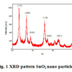 |
Figure 1: XRD pattern SnO2 nano particles Click here to View figure |
UV-vis absorption spectrum
The fig.2 shows that UV-visible absorption spectrum of SnO2 nano particles. The UV spectrum carried from 190 -1100 nm. UV-visible spectroscopy provides useful information about the optical band gap of the semiconductors. For the semiconductor nano particles, the quantum confinement effect is expected and the absorption edge will be shifted to a higher energy when the particle size decreases [22,23]. In the absorption spectrum shows the cut of wavelength of SnO2 nano particles is 210 nm.
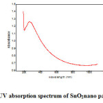 |
Figure 2: UV absorption spectrum of SnO2nano particles Click here to View figure |
Calculation of optical band gap
The fig.2 shows the optical bandgap of various pH samples were determined from the absorption spectra. The relation between the optical absorption coefficient hν and the photon energy was given by Mott and Davis[24] as
α (hν)=B(hν-Eg)n / hν——————-(1)
where B is a constant dependent on the transition probability, h is Planck’s constant, ν is the frequency of the radiation, and Eg is the optical energy gap. The type of transition responsible for the absorption depends on the value of n an index that can take any of the values 1/2, 3/2, 2 or 3 for direct-allowed, direct-forbidden, indirect-allowed, and indirect forbidden transitions, respectively. In the present case,n=1/2, which means an allowed direct transition. The optical absorption coefficient was calculated from the absorbance a using the following equation [25]
α(ν) =2.303 A/d ————- (2)
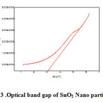 |
Figure 3: Optical band gap of SnO2 Nano particles Click here to View figure |
where d is the thickness of the sample in centimetre and A is calculated using the formula A=ln (I0/It)
where I0 and It are the intensities of incident and transmitted light, respectively.
For the determination of the direct optical band gap α2 was plotted as function of photon energy hν. When the dimensions of nano particles approach the exciton Bohr radius, a blue shift in energy is observed due to the quantum confinement. The band gap of SnO2 was found to be 3.16 eV. The effective mass model [26] is commonly used to study the size dependence of optical properties of quantum systems. The resultant values of Eg for freshly prepared SnO2 nanoparticle is found to be about 3.16 eV with splitting of energy [2,27].
FT-IR spectrum
The FT-IR spectrum was recorded for SnO2 nano particles after microwave treatment (fig. 4). The FTIR spectrum is recorded using Avatar 330 FT-IR thermo nicolet spectrometer in the wavelength range 400–4000 cm–1 by KBr pellet technique. The absorption band at 539 cm−1 was ascribed to the terminal oxygen vibration (νSn–OH) [29] for the dried precipitate. It was obvious that the hydroxyl group changed into oxide group during microwave radiation. After heating the product at higher sintering temperatures (1KW) a new broad band centred at 620 cm−1 appeared which was characteristic of oxide-bridge functional group (νOSnO)[30]. It was obvious that at this temperature the SnO2 had changed into SnO. The peaks at 1631 cm−1 were assigned to NH deformation of ammonia and NH stretching vibration respectively. The absorption band at 3323 cm−1 was mainly due to νOH stretching vibration of surface hydroxyl group or adsorbed water. For low pH value OH groups were still present at the surface and at the interior of the SnO particles. The remaining low signals attributed to some OH groups at the surface were probably due to the re-absorption of water from the ambient atmosphere [31].
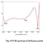 |
Figure 4: FT-IR spectrum of SnO2nano particles |
Scanning Electron Microscopy (SEM)
The morphology and chemical composition of the microwave synthesized tin oxide nanostructures were analyzed by SEM (fig.5). The micrograph of SnO2 sample shows the typical morphology of the SnO2 powders synthesized, characterized by the presence of particles with an average size of about 1 µm or less. In this study SnO2 nanoparticles found to be spherical.
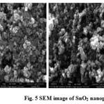 |
Figure 5: SEM image of SnO2 nanoparticles |
EDX spectrum
The fig 6 shows the EDX spectrum of SnO2 nano particles. The spectrum is confirmed the presence of elemental (stannum) tin oxide and oxygen. There was no other element not observed in EDX spectra. It shows the synthesized SnO2 is in high pure form. The table 3 mention the percentage of purity of SnO2 nano materials. The table 3 show the percentage of Sn & O in synthesized compound of nanoparticles.
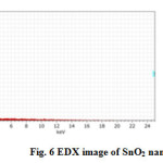 |
Figure 6: EDX image of SnO2 nanoparticles |
Measurements of CO2 level
The synthesized SnO2 nanoparticles were used as catalyst to reduce the carbon content of automobile fume. For this measurement we have chosen the pulsar bike (2002 model). The emission test was carried out by conventional emission test instrument, it records the emission for 0-60 seconds and it is shown in fig. 7a. Then the synthesized catalyst was spread on the wool rolled and put in the cylindrical tube. The tube fixed in the outer core of the silencer. The bike get started the smoke was measured the CO2 gas during the interval of the 0- 60 seconds and the results were shown in fig. 7 b. The amount of emitted CO2 is found reduced while using SnO2 catalyst. In this way the SnO2 catalyst used as a converter used red ox reactor to reduce the pollutants of the two wheelers.
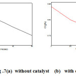 |
Figure 7: (a)without catalyst (b) with catalyst |
Conclusion
We have successfully synthesized SnO2 nano particles by microwave assisted method. The powder X-ray diffraction shows the good crystalline nature and particle size calculated using Debye scherrer formula. The calculated particle 57 nm. The band gap of SnO2 nano particles is measured from Tauc relation. Morphology was investigated carried from SEM. The EDX spectrum gives atomic percentage level of SnO2 nano particles. The SnO2 is identified as suitable material to reduce the Carbon from automobiles fume.
Acknowledgments
The authors convey the heart full gratitude to the management of SRM university for their motivation and support.
References
- Das, S.;Kar,S.; Chaudhuri, S.; J. Appl. Phys2006, 99, 114303
CrossRef - Gudiksen, M.S,;Lauhon,L. J.; Wang,J.; Smith,D.; Lieber,C. M.; Nature London2002, 415, 617-620.
CrossRef - Göpel, W.; Schierbaum,K. D.; Sens. Actuators B, 1995, 1,26–27
- Zhang,G.; Liu,M.;Sens. Actuators B, 2000, 69, 144-152 .
CrossRef - Ansari,G.;Boroojerdian,D.;Sainker, S.R.;Karekar,R. N.;Aiyer,R. C.; Kulkarni,S. K.;Thin Solid Films,1997, 295(1)271-276.
CrossRef - Law, M.; Kind, H.; Messer, B.; Kim, F.; Yang, P.; Angew.D.; Chem., Int. Ed.2002, 41, 2405-2408.
CrossRef - Harrison, P. G.; Willet, M.; J.Nature1988, 332- 337.
- Idota, Y.; Kubota, T.; Matsufuji, A.; Maekawa, Y.; Miyasaka,T.Science, 1997, 276, 1395-1397.
CrossRef - He, Y. S.; Campbell, J. C.; Murphy, R. C.; Arendt, M. F.; Swinnea, J. S.;J. Mater. Research.1993,8,3131.
CrossRef - Wang, Y.; Jiang, X.; Xia, Y.; J. Am. Chem. Soc,2003,125, 16176-16177
CrossRef - Kolmakov, A.; Zhang, Y.; Cheng, G.; Moskovits, M.AdV. Mater,2003, 15,997-1000.
CrossRef - Law, M.; Kind, H.; Messer, B.; Kim, F.;Yang, P.; Angew. Chem., Int. Ed,2002,41,2405-2408.
CrossRef - Comini, E.; Faglia, G.; Sberveglieri, G.; Pan, Z. W.; Wang, Z.; J. Appl. Phys. Lett.,2002,81,1869-1871.
CrossRef - FengGu, Shu Fen Wang, Chun Feng Song, Meng Kai Lu, Yong Xin Qi, Guang Jun Zhou, Dong Xu, Duo Rong Yuan, Chemical Physics Letters,2003,372,451-454.
- FengGu, Shu Fen Wang, Meng Kai Lu, Guang Jun Zhou, Dong Xu and Duo Rong Yuan, J. Phys. Chem. B,2004, 108,8119-8123
- Ying,Z.; Wan,Q.; Song,Z.T.; Feng, S.L.; Mater. Lett, 2005,59,1670-1672.
CrossRef - Liu,Y.; Dong, J.; Liu, M.; Adv. Mater.2004,16,353-356.
CrossRef - Ki Chang Song, Yong Kang, Materials Letters, 2000,42,283-289.
CrossRef - Hallila,H.; Méninia, P.;Auberta,H.;Procedia Chemistry,2009,1,935.
CrossRef - Zhang,J.;Gao,L.; Chem. Lett,2003,32,458.
CrossRef - Yang,H.; Song,X.; Zhang,X.; Ao,W.; Qui,G.;Mater. Lett,2003,57, 3124-3127.
CrossRef - Moldovan,D.;Yamakov,V.; Wolf,D.; Phillport,S.R.;Phys. Rev. Lett.2002,89,206101-206104
CrossRef - Das,S.; Kar, S.;Choudhary,S. ; J. Appl. Phys.2006,99,114303-114309.
CrossRef - Mott,N.F.; Davis,E.A.;Electronic Processes in Non-Crystalline Materials, Oxford, Clarendon, 1979.
- Fox,M.;Optical Properties of Solids, Oxford University Press, New York, 2001.
- Pankov,JI.;Optical Processes in Semiconductors, Prentice-Hall Inc.,EnglewoordCliffs,NJ; 1971.
- Patil G.E., Kajale D.D., Gaikwad V.B., Jain G.H., International Nano Letters 2012, 2:17.
CrossRef - Naje A.N., Norry. A.S., Suhail A.M., International Journal of Innovative Research in Science, Engineering and Technology2013,2 (12), 7068-7072.
- Zhang Jianrong, GaoLian, Inorganic Chemistry Communications, 2004, 7,91–93.
CrossRef - RaiRadheshyam, T.D.;Senguttuvan, S.T.;Lakshmikumar, Computational Materials Science, 2006, 37, 15–19.
- Yung-Jen Lin, Ching-Jiunn Wu, Surface and Coating Technology, 1996, 88,239–247
CrossRef

This work is licensed under a Creative Commons Attribution 4.0 International License.
About The Author
![]()
A New Edition of Web of Science
Journal Impact Factor
2022: 0.5
Five Year: 0.8
Journal is Indexed in

Cabells Whitelist
![]()


