Water Test Using NanoCrystalline Electrodes TiO2
Hassan Zhian1, Bahrooz Khezry2 and Chalak Azimi3
1Departement of chemistry, Mahabad Branch, Islamic Azad University, Mahabad, Iran
2Departement of chemistry, Mahabad Branch, Islamic Azad University, Mahabad, Iran
3Departement of chemistry, Piranshahr Branch, Islamic Azad University, Piranshahr, Iran
DOI : http://dx.doi.org/10.13005/ojc/300213
Article Received on :
Article Accepted on :
Article Published : 26 May 2014
Photocatalytic formic acid decomposition is done by electrochemical and photocatalytic methods andis studied in a single cabinet photoelectrochemical cellwhich is included TiO2 Nano crystalline electrodes. Due to P25 inactivitydegasa was prepared in plated glass with tin oxide.Applying +1 V ( SCE ) in the TiO2electrode leading to substantially increase in the rate of formic acid decomposition speed in anaerobic and weather broadcast conditionscomparetoopen circuit electrode.When solution was distributed with O2positive bias will not result in a significant increase in speed. The second cathode cabin added to the cell coincidence withphotocatalytic oxidation of formic acid to revival of copper ion from solution.DecomposedFormic acid in photoanod and copper, in copper mesh cathode was revived with high efficiency.
KEYWORDS:water treatment; photo catalysis; titanium dioxide; waste water; nanoelectrodes
Download this article as:| Copy the following to cite this article: Zhian H, Khezry B, Azimi C. Water Test Using NanoCrystalline Electrodes TiO2. Orient J Chem 2014;30(2). |
| Copy the following to cite this URL: Zhian H, Khezry B, Azimi C. Water Test Using NanoCrystalline Electrodes TiO2. Orient J Chem 2014;30(2). Available from: http://www.orientjchem.org/?p=3461 |
Introduction
Application of photocatalystsas a complement and replacement technology, have been widely reported for treatment of polluted waters1-2. Use of TiO2 as a suspension or in aqueous kind reactor, need an extra stage for recovery of catalyst3-4. If catalyst immobilized on a solid support and cover a matrices there is no longer need to recover the catalyst after the reaction. If protective sublayer able to conduct electricity, the result is photoanodeandmaybefix it in a single-or dual-Cabin photoelectrochemical Cell in which oxidation and reduction are physically separated. In single- cabin cell, anode and cathode are separated from each other by solution and external electrical bias could be electrochemically used for photocatalytic oxidation of organic pollutants of water5-6. Other researchers studied photocatalysts that activated by electrochemical method (EAP) and sensible increase in yield of decomposition of aqueous organic particles have been reported by using a positive electrical bias, in which TiO2 and O2 act as acceptors of electrons7-8. Also, electrochemical studies of such systems provide valuable information about mechanism of photocatalytic processes. In single-Cabin PEC natural electron acceptor is dissolved oxygen in solution9-10. Theoritically, every species with positive reduction potential compared to TiO2 potential flat band could be reduced. In fact, use of TiO2 suspension reactors have been offered for reduction of metals, but such systems have several drawbacks such as the necessity for reduction of metal, short cycle due to oxidation of Reduced metal species and cementation of catalyst by precipitated metals11. If TiO2 anode is combined to a dual-cabin PEC, in this case location of oxidation and reduction are physically separated by membrane or esalt bridge and in the same time prevent mixing of solutions and maintain electrical current12-13. In this system, photoelectrons from photoanodepossiblymoved from an external circuit to cathode and a desireable reduction reaction happened and metal ions reduced. Heretobefore use of dual-Cabin PEC for simultaneous oxidation of organic pollutants and single-Cabin reduction of metal ions in second cabin is approved.
Experimental Section
Preparation of TiO2 electrodes
And continued by a thermal experiment at 673 K in order to influence adherence of particles. Details of electrophoretic coating method have been explained before.A electrical contact accomplished by a loaded silver conductive epoxy and a copper wire in order to not contaminat surface of TiO2 Coated ITO. Loading of catalyst eaual to 1±0.2 mg/cm2.
single Cabin current reactor
sandwich type reactor prepared from Perspex in required dimension.Reactor design has been shown in Figure 1. CE made from platinized titanium network and reference electrode (RE) is saturated calomel electrode (SCE). Stainless steel is located in right angle in entrance and exit of reactor.
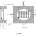 |
Figure 1 Click here to View Figure |
Entrance and exit part of reactor are equipped with glass acceptor water chamber.Water in reactor is circulated by a pump. Volume of cell is 35 cm3. Overall operational volume of reactor is 72 cm3. Reactor solution temperature during the experiments fixed on 293 K. Two Philips Lamp TLD 18W/08 UVA are equipped in 40mm-window of case. Bright region of TiO2 electrode are about 38 cm2 and intensity of the light are determined by radiometric FerroxalateEnstein method. Formic acid as a model pollutant has been selected and with initial concentration of 3.18×10⁻³ or 6.36×10⁻³mol dm-3 has been added to reactor. In an ordinary experiment 72 cm3 from formic acid has been added to reactor and for 15 min has been circulating by speed of 60 cm3/min in darkness. Then the lamps have been turned on and warmed. Acceptor with O2 or air without nitrogen during the dark period and experiment period were cleaned. Samples are separated from receptor in time t=0 and after 15 min analyzed. Concentration of formic acid in samples were determined by HPLC on a Aminex ion HPX-87H Column with a guard column P2000 and Autosampler AS1000 with a UV-Vis LIS detector and PC1000 software. Conditions of HPLC method are as follows
Mobile phase H2SO4 in flow rate of 1-10 mol.dm-3
Injection loop 100 ul
Detection at 210 nm
Electrode potential and current of short circuit was determined by a multimeter and log function information were recorded. During the constant potential experiment a PC was used for determination of potential of (LSV), evaluation of OC potential and Cell control and current.
Dual Cabin Current Reactor
As it is shown in Figure 2, second cabin is added to single cabin reactor. Active electrode was a TiO2-FTO glass electrode which in relation to CE electrode in Cathode cabin had a short rotation part made from four pieces copper lattice and wires. Anode Volume was 38 cm3 and cathode volume with copper lattice CE was about 26 cm3. Separate receptors for anode and cathode cabin have been used. Overall volume of half cells of anode and cathode are respectively 72 and 64 cm3. Anode and cathode cabins were separated from each other by (BDH) anion exchange membrane. Liquid inside the cabins are circulated by constant speed using a double head smoke pump. Anode potential were determined compare to available SEC in anode cabin and short circuit current was recorded by an induction multimeter. Both receptor before and during experiment were covered by OFN. Temperature of solution in reactor during the experiment was 293 K. 72 cm3 formic acid was added to anodic half-cell and 64 cm3 copper nitrate solution to cathodic half-cell. KNO3 as supporting electrolyte are present in both cabin in 0.5 mol/dm3. Solution were circulating for 15 min when receptore were covered by OFN and lamp were warming. Then sample has been taken from anode receptor in time t=0 and anode illuminated. Then samples every 30 min for 120 min were withdrawn. Concentration of formic acid by HPLC method explained before were determined. Amount of copper reduced were calculated by determination of weight of copper lattice at the end of experiment.
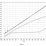 |
Figure 2 Click here to View Figure |
Linear sweep voltammograms measured in the one – compartment flow cell. Formice acid was present in the cell at 6.36×10⁻³mol dm-3 , sweep rate = 10m Vs-1 1)Air sparged , light 2) OFN sparged 3) O2 sparged, light 4) O2 sparged, dark.
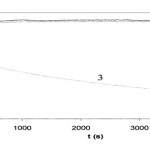 |
Figure Click here to View Figure |
photocurrent measured during electrochemically assisted photo catalytic degradation of formic acid. Initial concentration of formic acid was 6.36 × 10⁻³mol dm−3. Applied potential was +1.0V: (1) OFN sparged ; (2) air sparged; (3) O2sparged.
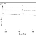 |
Figure 3 B Click here to View Figure |
OC potential of TiO2 electrode over time. Initial concentration of formic acid was 6.36 × 10⁻³mol dm−3: (1) OFN sparged; (2) air sparged; (3)O2sparged.
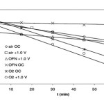 |
Figure 3 C Click here to View Figure |
Formic acid degradation over time for the electrode at OC and +1.0V in OFN sparged, air sparged, and O2sparged solutions. Initial concentration of formic acid was 6.36 × 10⁻³mol dm−3.
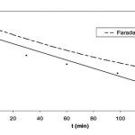 |
Figure 3 D Click here to View Figure |
Formic acid degradation on TiO2 anode short-circuited to copper CE in the two-compartment PEC with Cu2+as the electron acceptor. The initial concentration of formic acid was 6.0×10⁻³mol dm−3. Faradaic: the formic acid degradation as calculated using the measured short-circuit photocurrent.
Result and Discussion
TiO2nanocrystaline electrodes which prepared by P25 degasa electrophoretic fixation method on tin oxide glass, showed high yield in decomposition of formic acid in dual and mono-cabin PEC.When the O2 Concentration in Solution is low, use of one volt potential for TiO2 electrode lead to salient increase in rate of decomposition of formic acid. In O2 saturated solutions, no sensible increase in rate of decomposition compared to OC-electrode has been observed. In dual-Cabin PEC, formic acid decomposes in anode. Cathode is made from Copper in which Cu2+ reduced to Cu. Preliminary IPEC for this system was 9.5 %. Its need more research to decide whether this technology will work with real industrial solution and natural sun shine or not.
Acknowledgements
The authors could express their sincere thanks to the Islamic Azad University, Mahabad Branch and persons that has supported this work.
References
- A. Mills, S. Le Hunte, J. Photochem. Photobiol. A 108 (1997) 1–35.
- J.A. Byrne, B.R. Eggins, N.M.D. Brown, B. McKinney, M. Rouse,Appl. Catal. B 17 (1998) 25–36.
- K. Vinodgopal, S. Hotchandani, P.V. Kamat, J. Phys. Chem. 97(1993) 9040–9044.
- K. Vinodgopal, U. Stafford, K.A. Gray, P.V. Kamat, J. Phys. Chem.98 (1994) 6797–6803.
- K. Vinodgopal, P.V. Kamat, Solar Energy Mater. Solar Cells 38(1995) 401–410.
- R. Pelegrini, P. Peralta-Zamora, A.R. de Andrade, J. Reyes, N. Duran,Appl. Catal. B 22 (1999) 83–90.
- J. Rodrigez, M. Gomez, S.E. Lindquist, C.G. Granqvist, Thin Solid Films 360 (2000) 250–255.
- S.A. Walker, P.A. Christensen, K.E. Shaw, G.M. Walker, J.Electroanal. Chem. 393 (1995) 137–140.
- P. Mandelbaum, S.A. Bilmes, A.E. Regazzoni, M.A. Blesa, Solar Energy 65 (1999) 75–80.
- D.H. Kim, M.A. Anderson, J. Photochem. Photobiol. A 94 (1996)221–229.
- D.H. Kim, M.A. Anderson, Environ. Sci. Technol. 28 (1994) 479–483.
- H. Hidaka, K. Ajisaka, S. Horikoshi, T. Oyama, K. Takeuchi, J.Zhao, N. Serpone, J. Photochem. Photobiol. A 138 (2001) 185–192.
- H. Hidaka, K. Ajisaka, S. Horikoshi, T. Oyama, K. Takeuchi, J. Zhao, N. Serpone, Catal. Lett. 60 (1999) 95–98.

This work is licensed under a Creative Commons Attribution 4.0 International License.
![]()
A New Edition of Web of Science
Journal Impact Factor
2022: 0.5
Five Year: 0.8
Journal is Indexed in

Cabells Whitelist
![]()


