Voltammetric Study and Determination of Phenylephrine Hydrochloride at INP-Nafion-Modified CPE Sensor Employing Differential Pulse Voltammetry
Zeinab Pourghobadi, Ali Niazi *
Department of Chemistry, Faculty of Science, Arak Branch, Islamic Azad University, Arak, Iran
DOI : http://dx.doi.org/10.13005/ojc/300126
Article Received on :
Article Accepted on :
Article Published : 13 Mar 2014
In this study, describes the voltammetric oxidation and determination of phenylephrine (PHE) hydrochloride at a new chemically modified electrode. Iron nanoparticle (INPs) was dispersed in Nafion solution to obtain a INP-Nafion-modified CPE for the voltammetric analysis of PHE .The electrochemical behaviour of PHE on INP-Nafion-modified CPE was studied, using cyclic voltammetry as a diagnostic technique. The effects of amount of INPs-Nafion dispersion, pH, and scan rate on the response of modified electrode for the oxidation of PHE were investigated. Using differential pulse voltammetry (DPV), the modified electrode indicated a dynamic linear range for quantitative determination of PHE in the range of 5 μM−130 μM, and the detection limit was estimated to be 0.76 μM. The method was developed for the determination of PHE in pharmaceutical samples with satisfactory results.
KEYWORDS:Phenylephrine Hydrochloride; Differential Pulse Voltammetry; Determination; Iron nanoparticles; Modified electrodes; Nafion.
Download this article as:| Copy the following to cite this article: Pourghobadi Z, Niazi A . Voltammetric Study and Determination of Phenylephrine Hydrochloride at INP-Nafion-Modified CPE Sensor Employing Differential Pulse Voltammetry. Orient J Chem 2014;30(1) |
| Copy the following to cite this URL: Pourghobadi Z, Niazi A . Voltammetric Study and Determination of Phenylephrine Hydrochloride at INP-Nafion-Modified CPE Sensor Employing Differential Pulse Voltammetry. Orient J Chem 2014;30(1). Available from: http://www.orientjchem.org/?p=2352 |
INTRODUCTION
Phenylephrine hydrochloride, PHE, (R)-3-hydroxy-α-[(methylamino) methyl] enzenemethanol hydrochloride, is a sympathomimetic drug widely used in the treatment of hypertension , schizophrenia, nasal congestion, sinusitis , rhinitis , and the symptomatic relief of cold symptoms [1, 2]. It may be used alone or in combination with other agents for active ingredients PHE is present in the formulation of several vasopressor medicines, in eye drops, in nasal decongestant, in syrups and tablets. Several analytical techniques such as Spectrofluorimetry [3, 4], Colorimetric [5, 6], high performance liquid chromatography [7-11], flow injection analysis [12, 13], spectrophotometry [14-18].
However, these methods have a number of disadvantages as: requires expensive devices, require pretreatment, time consuming and solvent-usage intensive. . Some electrochemical methods are also reported for the determination of PHE [19-27]. Electrochemical methods exhibits its predominance such as simple, high sensitivity, low cost, stability and often do not require any pre-treatments or pre-separation. The unique properties of nanoparticles such as Fe, Ni, Co, and their oxides, have found broad application in electroanalysis methods [28-30]. Magnetic nanoparticles or iron nanoparticles (INPs) have excellent high-density, conductivity, catalytic, unusual physical and chemical properties, which make them suitable for acting as the electrocatalytic reaction process and voltammetric sensing of some small electroactive molecules because of their attractive properties such as superparamagnetism, low toxicity, good biocompatibility, and excellent nanocharacter. In recent years, several reported related to electrochemical sensors and biosensors based on nanomaterials have mentioned the important roles of nanoparticles [31-38].
Nafion (NAF) is a perfluorosulfonated cation exchange polymer, which has been extensively applied in the modification of the electrode surfaces and in the construction of different functional biosensors for its unique, high chemical stability, good biocompatibility, easy fabrication, good electrical conductivity, and as a support for nanoparticles has been widely used as a protective coating material. . As Nafion films, an ion-exchange polymer are highly permeable to cations but almost impermeable to anions [39, 40]. Also INPs can be homogeneously dispersed in Nafion solution cause favorable mass transport to surfaces and can permit magnetic capture of depleted materials. Carbon paste electrode (CPE) used extensively as working electrodes for a variety of electrochemical applications and due to low background current compared with other solid electrodes, easy renewability of the surface, low cost, facility to prepare, large potential window, and compatible with various types of modifiers. CPEs can be modified by using various electron transfer mediators such as INPs [41, 42]. Therefore, in this work we attempt to synthesis Iron nanoparticle (INPs) was dispersed in Nafion solution to obtain a INP-Nafion-modified CPE and then the electrocatalysis of PHE using cyclic voltammetry and differential pulse voltammetry (DPV) method.
EXPERIMENTAL
Chemicals and reagents
All of the solutions were freshly prepared using double-distilled water. Phenylephrine hydrochloride (PHE) reference was kindly provided by Darou Pakhsh Pharmaceutical Company (Tehran, Iran). Ferric chloride (FeCl3·6H2O), ferrous chloride (FeCl2·4H2O), ammonia solution (25 wt. %), sodium hydroxide, hydrochloric acid (37 wt.%) were obtained from Merck (Darmstadt, Germany) The 5 (v/v %) Nafion solution used in this study was prepared by diluting the 5 (wt %) Nafion in ethanol was purchased from Fluka. Stock solutions of Phenylephrine hydrochloride (0.010 mol L-1) was freshly prepared daily by dissolving PHE in water and protected from light during investigation. The buffer solutions were prepared from ortho-phosphoric acid and its salts) (pHS 2, 3, 6, 7, 8, 9), and acetate buffer solutions (pHs 4, 5) as supporting electrolytes. Graphite fine powder and paraffin oil (both from Merck) were used as binding agents for the graphite pastes. The PHE containing nasal sprays 0. 5% and 0.25% were purchased from Sina Daru Pharmaceutical Co. (Tehran, Iran) respectively.
Synthesis of Iron nanoparticle (INPs)
Various methods of deposition of INPs have been investigated [43]. In this work, First, 5.2 g of FeCl3·6H2O in 2 mL HCl (12 mol L-1) dissolved and with 2 g of FeCl2·4H2O was mixed then 100 mL of deionized water in a beaker which was degassed using nitrogen gas added. Then, this stock solution under nitrogen atmosphere with vigorous stirring heated to 70 °C .the ammonia solution (2 mol L-1) was added to beaker while vigorous stirring and heated to 70 °C . After the reaction completed (pH=10) the nanoparticles were collected by the magnet and thoroughly washed with deionized water to remove excess amounts of ammonium hydroxide. Then, the nanoparticles were dried in an oven for 1h at 70 °C.
Instrumentation
A potentiostat / galvanostat (SAMA 500, electroanalyzer system, I.R. Iran) was used for carrying out the electrochemical experiments. A three electrode cell was used at 25 ± 1 °C. A saturated calomel electrode, platinum wire, and a carbon-paste working electrode (unmodified or modified) were used as reference, auxiliary and working electrodes, respectively. A Metrohm model 780 pH/mV meter was also used for pH measurements, 1.6 Tesla magnetic field, (7×3×2 cm) from Tehran Magnet .A magnetic-stirrer HP – 3000 model.
Preparation of the INP-Nafion-Modified CPE
Carbon paste was made according to the literature by thoroughly mixing high purity graphite powder and paraffin oil [44]. A portion of the resulting paste was packed into the end of an insulin syringe. Electrical contact to the paste was established by inserting a copper wire down through the syringe and into the back of the mixture. Before each dispersion, the working electrode surface was smoothed by polishing with paper. Finally, 10 μL of homogeneous INP-Nafion dispersion, which was obtained by dispersing 3 mg of INPs in 1 mL of 5 (v/v) Nafion solution diluted with ethanol with the aid of 25 min ultrasonic agitation, was cast on the surface of the CPE and then dried in air to get the INP-Nafion-modified CPE.
General Procedure
INP-Nafion-modified CPE was immersed in phosphate buffer solution by cyclic voltammetry from 0.6 to 1.2 V until a stable cyclic voltammogram was obtained. Then, appropriate volumes of sample solution (PHE) were added to the voltammetric cell, differential pulse voltammograms were recorded and used for plotting the calibration curve. The potential was swept from +0.6 to +1.2 V versus SCE with a scan rate of 100 mVs−1.
Real sample analysis
The contents of three bottles of nasal spray were mixed separately (each bottle contains 0. 5% and 0.25% of PHE hydrochloride for nasal spray respectively). A specific amount of these mixtures, which was equivalent to a stock solution with a concentration of about 1.0×10⁻² mol L-1, was accurately transferred into a 100 mL calibrated flask and completed to the volume with double distilled water. Then, 2.0 mL of the solution plus 17.0 mL of the buffer (pH 3.0) were used for the analysis with standard addition method. Quantizations were performed using the calibration curve method from the related calibration equations.
RESULTS AND DISCUSSION
Electrochemical studies
The electrochemical behavior of PHE at unmodified electrode (bare) and the INP-Nafion-modified CPE was investigated in 1 mM PHE (pH 3) by cyclic voltammetry. AS shown in Fig. 1. It can be seen the curves (a) and (b) exhibits the voltammetric response of the INP-Nafion-modified CPE unmodified electrode (bare) in the presence of PHE, respectively. Its anodic peak potential (the INP-Nafion-modified) shifted negatively and the peak currents also increased significantly.
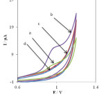 |
Fig. 1. Cyclic voltammograms in the presence of 0.1 mM PHE at unmodified electrode (curve a), the INP-Nafion-modified CPE (curve b) and in the absence of PHE at the surface of an unmodified electrode (curve c) and the INP-Nafion-modified CPE (curve d), in phosphate buffer solution of pH 3, scan rate, 100 mV s-1.Click here to View Figure |
As can be seen, there is no voltammetric peak for the blank solution and in the absence of PHE (in phosphate buffer solution pH 3.0) at the surface of the INP-Nafion-modified (curve c) and unmodified electrode (curve d) in buffer solution. Comparing the INP-Nafion-modified CPE response with when the CPE was only coated with Nafion, the peak currents of PHE could increase a little. These results proved that the INP-Nafion-modified CPE exhibits an obvious electrocatalytic response and the kinetics of electron transfer improves remarkably toward PHE. The effective catalytic role of the modified electrode toward PHE oxidation can be attributed to electrocatalytic activity of INP-Nafion in the paste matrix. INPs could improve the electrochemical activity of PHE with accelerating the rate of electron transfer and mass transport between the electrode and PHE because of its unique physical and chemical properties such as better conductivity, large specific surface area, and good biocompatibility. Moreover, the polyanion surfactant of Nafion could attract and accumulate cationic PHE in some degree and result in the further increase of the peak currents. Study on the electrochemical properties of PHE at the INP-Nafion-modified CPE was investigated in solution buffer (pH 3) using cyclic voltammetry. (Fig. 2A) exhibits the cyclic voltammogram of PHE at the INP-Nafion-modified CPE under the optimum conditions and a scan rate of 100mVs−1 For the concentration range of 100–800 μM PHE, the regression equation was I (μA) =39.039 C (μм) + 19.087 and a correlation coefficient of R2 =0.9968 (Fig. 2 B).
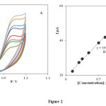 |
Fig. 2. Cyclic voltammogram of PHE at the INP-Nafion-modified CPE under the optimum conditions and a scan rate of 100 mVs−1 for the concentration range of 100–800 μM PHE.Click here to View Figure |
Effect of the Amount of INP-Nafion Dispersion
To study the effect of the amounts of INPs-Nafion dispersion coated onto the CPE the electrochemical behavior of PHE, different modified electrodes were fabricated with different amount of this dispersion. It was found that the peak current of PHE increased with the increase of the dispersion amount, and it reached the maximal value when 10 mL of INP-Nafion was cast on the surface of a CPE and dried in air. With the increase of the dispersion amount, the response current of PHE would decrease. The reason may be that a lower amount of the dispersion would result in the CPE surface not being coated uniformly. However, too much dispersion would form a relatively thick film, which could decrease the mass transfer rate of PHE with the electrode [36], so INP-Nafion dispersion of 10 mL was considered as the optimum value Fig. 3.
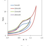 |
Fig. 3. Cyclic voltammograms of 0.1mM PHE various amount of INPs-Nafion dispersion at CPE under the optimum conditions in phosphate buffer solution of pH 3, scan rate, 100 mV s-1.Click here to View Figure |
Effect of solution pH
The effect of solution pH on the electrochemical response PHE at the INP-Nafion-Modified CPE was investigated using CV in the pH range from 2 to 8. As shown in Fig. 4 the anodic peak current was gradually decreased by increasing the pH from 2.0 to 8.0.
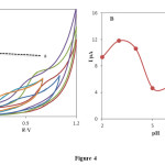 |
Fig. 4. (A) Cyclic voltammograms of 0.1m M PHE at the surface of the INP-Nafion-modified CPE immersed in in phosphate buffer solution PH 2, 3, 6,and 7, acetate buffer pH 4 and 5, scan rate 100 mV/s; (B) variation of anodic peak potential vs various pH values in 0.1 mM PHE.Click here to View Figure |
However, it was disappeared by further increasing in pH of the solution. It is increasingly deprotonated for its acid-base properties phenylephrine .PHE has two pK values: 8.77, attributed to its basic secondary amine and 9.84, due to its phenol group [45]. By increasing the pH of solution gradually the free form of PHE base in the test solution was increased which was not sensed by the INP-Nafion-Modified CPE, so, the maximum anodic current was obtained at pH 3, therefore it was chosen as the optimal pH for next experiments. The relationship between the anodic peak potential and the solution pH value could be fit for the regression equation of Epa (V) = -0.055 pH + 1.1613, with a correlation coefficient of R² = 0.9933. A slope of 55mV pH−1 suggests that the number of electron transfer is equal to that of hydrogen ions taking part in the electrode reaction, which is close to the theoretical value of -59 mV Fig 5.
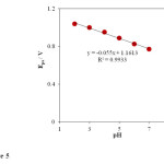 |
Fig. 5. Effect of buffer pH on the oxidation peak potential (Epa). Conditions are the same as in Fig. 4.Click here to View Figure |
Effect of scan rate
The effect of scan rate on the electrooxidation of 1.0 × 10⁻³ mol L-1 PHE at the INP-Nafion-modified CPE in a buffered solution of pH 3.0 at different potential sweep rates was examined by cyclic voltammetry. (Fig. 6 A), exhibits the cyclic voltammograms of PHE at the INP-Nafion-modified with different scan rates, ν, in the range of 10−200 mV s−1. For PHE no cathodic peak is observed on the reverse scan in various potential sweep rates (Fig. 6 B). The anodic peak current varied linearly with the scan rates I (μA) = 0.0769 v (mV s-1) + 1.1338 (R² = 0.998) which shows that the oxidation of PHE on the INP-Nafion-modified was a typical absorption-controlled process [46].
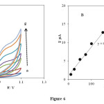 |
Fig. 6. (A) Effect of the scan rates on the cyclic voltammetric responses in phosphate buffer solution of pH 3 at the INP-Nafion-modified CPE for .1mM PHE at various scan rates (from 10 to 300): 10, 25, 50, 75, 100, 150 and 200 mV s−1. (B) The relationship of anodic peak currents and the scan rate for PHE (0.1Mm).Click here to View Figure |
Analytical Measurements
Differential pulse voltammetry (DPV) was used to investigate as a highly sensitive and rapid electrochemical method for the determination of PHE. Therefore, differential pulse voltammetry experiments were performed using the INP-Nafion-modified CPE in a buffered solution of pH 3.0 containing various individual concentrations of PHE. The results (Fig 7 A) show DPVs of PHE oxidation at the surface of the INP-Nafion-modified CPE were linearly dependent on the PHE concentrations, over the range of the range from 5 to 130 μM (Fig 7 B), and the linear regression equation was Ip (μA) = 0.1551 C (μM) + 2.8631 with a correlation coefficient of R2=0.9986 and the detection limit (S/N=3) was estimated to be 0.76 μM.
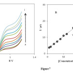 |
Fig. 7. (A) DPVs of 5.0 (a), 10.0 (b), 20.0 (c), 30.0 (d), 40.0 (e), 50.0 (f), 60.0 (g), 80.0 (h), 100.0 (i), 110.0 and 130 μM PHE on the INP-Nafion-modified CPE under the optimum conditions and a scan rate of 100 mVs−1. (B) Plot of the peak current in differential pulse voltammetry versus the concentration of PHE.Click here to View Figure |
Detection limit and linear calibration range of the proposed modified electrode were compared with those obtained in other reports and the results are summarized in Table 1.Although the linear range of the proposed modified electrode is smaller than those reported in some previous works its detection limit is comparable or better than the results reported for PHE determination at the surface of recently fabricated modified electrodes [20-23, 25].
Table 1: Comparison of this work with other reported electrochemical methods.
|
Method |
Electrode |
Linear range (M) |
LOD (M) |
RSD (%) |
Reference
|
|
DPV |
NiNP-CPE |
2.0 × 10⁻⁵ – 1.0 × 10⁻² |
6.4 × 10⁻⁶ |
0.73 |
42 |
|
Potentiometry |
TPB-CGE |
3.0 × 10⁻⁶ – 5.6 × 10⁻² |
1.5 × 10⁻⁶ |
– |
37 |
|
Potentiometry |
TPB-PVC |
1.5 × 10⁻⁴ – 1.0 × 10 −1 |
– |
– |
35 |
|
DPASV |
CE-CPE |
3.0 × 10⁻⁵ – 1.0 × 10⁻⁴ |
2.0 x 10⁻⁶ |
4.20 |
38 |
|
DPV |
MIP-GCE |
Nonlinear |
– |
– |
41 |
|
DPV |
INP-modified-CPE |
5× 10⁻⁶ – 1.3× 10⁻⁵ |
7.6× 10⁻⁷ |
3.6 |
This work |
Reproducibility and Stability
To evaluate the reproducibility of the INP-Nafion-modified CPE by DPV, the peak currents of (n= 5) successive detections in a solution of 50 μM PHE was determined. The relative standard (RSD) is 2.53 %, showing that the INP-Nafion-modified CPE has good repeatability. The storage stability of the INP-Nafion-modified CPE was also investigated. For detection of 50 μM, no significant decrease in current response was found in the first 7 days. A 95% current response was still retained after 1 month. Therefore, the stability of the proposed electrode was good enough for continual operation.
Interference Studies
The influence of various foreign species on the determination of 20μM PHE The tolerance limit was taken as the maximum concentration of the interfering substances that caused an approximately 5% relative error in their determinations. The results are given that the presence of these coexists species had no influence on the current response of 20 μM of PHE under the optimum conditions at the applied potential; the results are given in Table 2. The results indicated that no interference on the determination of PHE was observed.
Table 2: Interference of some foreign species on the determination of 20.0 μM PHE under the optimized conditions.
| Foreign species | Tolerant limits (Wsubstance/WCSH) |
| urea, glucose, tyrosine, | 200 |
| Chlorpheniramine, ascorbic acid | 100 |
Determination of PHE Real sample analysis
To demonstrate the application of the INP-Nafion-modified CPE sensor, PHE concentrations in real samples were measured. The standard addition method is suitable for simple and rapid evaluation of PHE. The recoveries of PHE from real samples were measured by spiking drug with a known amount of PHE. Table 3 shows the results analysis of PHE in real samples. As it is obvious, these results indicate that the INP-Nafion-modified CPE can be used for voltammetric determination of PHE in real samples with the good recoveries of the spiked PHE in the range of 96–104%.and good reproducibility.
Table 3: Determination of PHE in nasal spray samples under the optimum conditions (n = 3).
| Sample |
Spiked (µM) |
Found (µM) |
Recovery (%) |
| Nasal spray (0.25%) |
20.0 |
19.2 |
96.0 ± 0.4 |
|
80.0 |
80.9 |
101.1 ± 0.3 |
|
| Nasal spray (0.50) |
40.0 |
41.2 |
103.0 ± 0.2 |
|
70.0 |
73.0 |
104.3 ± 0.1 |
CONCLUSION
In this research, the INP-Nafion-modified CPE was successfully fabricated by INPs-Nafion dispersion coated onto the CPE as modifying species. Modifiers in the modified CPE exhibited some excellent characteristics, including: good dispersing properties, large surface area, good electrical conductivity and fast electron transfer .The experimental results showed that INP-Nafion-modified CPE high electrocatalytic activity for the oxidation of PHE Under the optimum conditions. The modified electrode can be used successfully to determine PHE in drug samples.
REFERENCES
- K. Parfitt, The Complete Drug Reference, 32nd ed., Pharmaceutical Press, London 1999.
- J. H. Hengstmann, J. Goronzy, Eur. J. Clin. Pharmacol., 21: 335 (1981).
- J.A. Arancibia, A.J. Nepote, G.M. Escandar, A.C. Olivieri, Anal. Chim. Acta, 419: 159 (2000).
- A.J. Nepote, A.C. Olivieri, Anal. Chim. Acta, 439: 87 (2001).
- C.F. Hiskey, N. Levin, J. Pharm. Sci., 50: 5 (1961).
- C.A. Kelly, M.E. Auerbach, J. Pharm. Sci., 50: 211 (1961).
- V. Vuma, I. Kafer, J. Chromatogr. B, 678: 245 (1996).
- M.J. Galmier, A.M. Frasey, S. Meski, E. Beyssac, J. Petit, J.M. Aiache, C. Lartigue, Biomed. Chromatogr., 14: 202 (2000).
- I.W. Lau, C.S. Mok, J. Chromatogr. A, 693: 45 (1995).
- N. Erk, M. Kartal, Farmaco, 53: 617 (1998).
- K. Gumbhir, W.D. Mason, J. Pharm. Biomed. Anal., 14: 623 (1996).
- J.R.C. Rocha, C.X. Galhardo, M. Auxiliadora, E. Natividade, J.C. Masini, J. AOAC Int., 85: 875 (2002).
- M. Knochen, J. Giglio, Talanta, 64: 1226 (2004).
- H. Mahgoub, Drug Dev. Ind. Pharm., 16: 2135 (1990).
- E.H. El-Mossalamy, Spectrochim. Acta Part A, 60: 1161 (2004).
- S.A. Shama, J. Pharm. Biomed. Anal., 30: 1385 (2002).
- N.W. Beyene, J.F. Van Staden, Talanta, 63: 599 (2004).
- S.A. Shama, J. Pharm. Biomed. Anal., 30: 1385 (2002).
- C. A. Lucy, F.F. Cantwell, Anal. Chem., 58: 2727 (1986).
- A.F. Shoukry, R. El-Sheikh, Y.M. Issa, M. Zareh, Anal. Chim. Acta, 99: 101 (1989).
- A. Soleymanpour, S. Abdifar, R. Bani, Electroanalysis, 23: 2813 (2011).
- J.C. Perlado, A. Zapardiel, E. Bermejo, J.A. Pérez, L. Hernández, Anal. Chim. Acta, 305: 83 (1995).
- L. Yao, Y. Tang, W. Zeng, Z. Huang, Anal. Sci., 25: 1089 (2009).
- Y. Zhua, Z. Zhang, W. Zhao, D. Pang, Sensors Actuators B, 119: 308 (2006).
- A. Samadi-Maybodi, S.K.H. Nejad-Darzi, H. Ilkhani, Anal. Bioanal. Electrochem., 3: 134 (2011). [26] F. Huang, G. Jin, Y. Liu, J. Kong, Talanta, 74: 1435 (2008).
- K. Li, M. Zhu, H. Zhang, J. Zhao, Int. J. Electrochem. Sci., 8: 4047 (2013).
- M. Yang, J. Jiang, Y. Yang, X. Chen, G. Shen, R. Yu, Biosensors and Bioelectronics, 21: 1791 (2006).
- S. Lv, H. Suo, J. Wang, Y. Wang, C. Zhao, S. Xing, Colloids and Surfaces A: Physicochem. Eng. Aspects, 396: 292 (2012).
- J. Pan, Q. W. Yang, Anal. Bioanal. Chem., 388: 279 (2007).
- H.L. Zhang, X.Z. Zou, G.S. Lai, D.Y. Han, F. Wang, Electroanalysis, 19: 1869 (2007).
- D.J. Kim, Y.K. Lyu, H.N. Choi, I.H. Min, W.Y. Lee, Chem. Commun., 2966 (2005).
- S. Yuan, W. Chen, S. Hu, Mater. Sci. Eng. C, 25: 479 (2005).
- S.M. Chen, J.Y. Chen, V.S. Vasantha, Electrochim. Acta, 52: 455 (2006).
- S.F. Wang, F. Xie, R.F. Hu, Sens. Actuators B, 123: 495 (2007).
- G.S. Lai, H.L. Zhang, D.Y. Han, Microchim. Acta, 160: 233 (2008).
- H. Teymourian, A. Salimi, S. Khezrian, Biosensors and Bioelectronics, 49: 1 (2013).
- G. Zhao, J.J. Feng, Q.L. Zhang, S.P. Li, H.Y. Chen, Chem. Mater., 17: 3154 (2005).
- G.A. Gerhardt, A.F. Oke, G. Nagy, B. Moghaddam, R.N. Adams, Brain Research, 290: 390 (1984).
- G. Nagy, G.A. Gerhardt, A.F. Oke, M.E. Rice, R.N. Adams, M.N. Szentirmay, C.R. Martin, J. Electroanalytical Chem., 188: 85 (1985).
- S. Shahrokhian, H.R. Zare-Mehrjardi, Electroanalysis, 19: 2234 (2007).
- G.S. Lai, H.L. Zhang, D.Y. Han, Anal. Lett., 41: 3088 (2008).
- A. Kaushik, R. Khan, P.R. Solanki, P. Pandey, J. Alam, S. Ahmad, B.D. Malhotra, Biosens. Bioelectron., 24: 676 (2008).
- D. Du, S. Liu, J. Chen, H. Ju, H. Lian, J. Lia, Biomaterials, 26: 6487 (2005).
- S. Riegelman, L.A. Strait, E.Z. Fischer, J. Pharm. Sci., 51: 129 (1962).
- H. Yin, Y. Zhou, S. Ai, Q. Chen, X. Liu, L. Zhu, J. Hazard. Mater., 174: 236 (2010).

This work is licensed under a Creative Commons Attribution 4.0 International License.
![]()
A New Edition of Web of Science
Journal Impact Factor
2022: 0.5
Five Year: 0.8
Journal is Indexed in

Cabells Whitelist
![]()


