Mechanics of Corrosion of Trip-Assisted Steels in Different Nacl Solutions
Animesh Talapatra1, Jayti Datta2* and N.R. Bandyopadhyay3
1MCKVIE, Department of Automobile (Under WBUT) Liluah, Howrah - 711 204, India. 2Faculty, Department of Chemistry, BESU, Shibpur, Howrah - 711 103, India. 3School of Materials Science and Engineering BESU, Shibpur, Howrah - 711 103, India
Mechanics of corrosion of two TRIP-assisted steels designated as A (having no Cr and Cu content) and B (having higher Ni, Cr and Cu content) heat treated at different condition to alter micro-structure phases. After two TRIP –assisted steels have been studied under the simulated condition of sea atmosphere in the laboratory scale in different level of salinity under the influence of neutral pH as well as exposing them in real sea water condition by using electrochemical test. Micro-structural characterization of Pre & post corrosive samples and quantitative phase analysis were carried out to arrive at heat treatment-structure-properties co-relation to get knowledge about mechanics of TRIP-assisted steels in different NaCl solutions.
KEYWORDS:Corrosion; TRIP-assisted Steel; Electro-chemical test; Phase analysis; Heat treatment
Download this article as:| Copy the following to cite this article: Talapatra A, Datta J, Bandyopadhyay N. R. Mechanics of Corrosion of Trip-Assisted Steels in Different Nacl Solutions. Orient J Chem 2012;28(3). |
| Copy the following to cite this URL: Talapatra A, Datta J, Bandyopadhyay N. R. Mechanics of Corrosion of Trip-Assisted Steels in Different Nacl Solutions. Available from: http://www.orientjchem.org/?p=23134 |
Introduction
From the history of steel development for vehicle, we can see that there were many kinds steels, which had been developed and used. From the 1950’s to the 1960’s, the rimmed steel was researched and used. From the 1960’s to 1970’s, many killed steels were developed and employed. From the 1980’s to the 1990’s, to highly improve the formability of sheet steel , the research of auto steel was mainly centralized in interstitial-free(IF) steel. By the 21st century, most projects of auto steel focused on developing new kinds of HSS and new style steels to meet the needs of the plan of ultra light steel auto body (ULSAB).These steels include double-phase (DP)steel, TRIP-steel and TWIP steel.
The former steels also known as high tensile steels (HT S) have moderate strength (350MPa) and increased strength through pearlite strengthening by the addition of carbon upto 0.2%. In 1960’s quenched and tempered (Q and T) steels were developed to improve the performance of industrial applications [5]-[7]. Due to higher carbon contents these suffer from poor weld ability and for this reason new classes of steels having low carbon content and higher alloy elements were developed. Steels having a fully austenitic microstructure are called TRIP steels (Zackay et al., 1967). These steels tend to be rich in nickel and other expensive austenite stabilising elements. By contrast, austenite is only a minor phase in the overall microstructures of TRIP-assisted steels (Matsumura et al., 1987; Takechi et al.,1987).
Development of newer types of low alloy high strength corros ion res istance s teel has been attempted by many res earchers all over the world for indus trial application in s ea atmos phere [1]-[6].
The major factors those effects the corros ion rate of HSLA steel are
Chemical composition
Composition of sea atmosphere
Type of e xpos ures
In moderate-velocity and high velocity sea atmos phere, Ni bas e alloy is frequently used for pumping. It has excellent resistance to cavitations, eros ion and exhib its corros ion rates of less than 0.025 mm/year. Other Ni-bas e alloys containing Cr and Mo offer increased res is tance to localized corros ion in s tagnant s ea atmos phere. Sea water is a highly conductive environ ment with 3.4% s alt (NaCl) concentration [3]-[6].Approximately 91.1% of the dissolved s alts are chlorides. There are other commonly occurring cons tituent, dissolved gases, living organis ms and various other materials found in sea water. Keeping in v iew of the above s tudy on corros ion behaviours to moderately lo w ca rbon s teel having Si, Mn, Ni, V, Nb, Mo, Cu and Cr des igned and develop for industrial application in s ea atmos phere has been attempted in this s tudy. No data base being available in literature on the systematic study on the effect of corros ionon multi-phas e micros tructure. It is essential to do more study in corrosion behaviour and performance of the material in order to evaluate and improve the design, cost effectiveness and reliability of each material used. Khoshnaw et al. (2007) have studied fatigue strength of low alloy steels in chloride solution. Turnbull et al. (2008) have studied stress corrosion cracking of stainless steel in chloride solutions. Chen et al. (2005) have studied mechanical properties of low-alloy steels in atmosphere containing chloride in tension test.
Exp Erimental P Rocedure
Materials
Here Two moderately lo w Carbon high strength low alloy steels for sea atmosphere application is designated as A and B having compos ition given in Table I were supplied by DM RL, Hyderabad.
Comosition of Materials
Composition of Met
Heat treatment
Steels were heat treated as per s schedules as shown in below in
Table II to develop diffe rent micros tructure.
| Steel | Schedule
No |
Heat treatment | Designation |
|
A |
1 |
As received (oil quenched
and temp ered) |
A1 |
|
2 |
Held at 9500C for
1/2hr,air coo led, Held at 7000C for 2 hrs, quenched to 4000C(salt bath), held for 900s and oil quenched. |
A2 |
|
|
3 |
Held at 9500 C for half an
hour, oil quenched in an oil of 0.123 centistokes viscosity. |
A3 |
|
|
4 |
Held at 9500 C for half an
hour then cooled in water |
A4 |
|
|
5 |
Held at 9500C for half
hour then cooled in air |
A5 |
|
|
6 |
Held at 9500C for 1/2hr.,
then cooled in furnace by switching off. |
A6 |
|
|
B |
1 |
As received (water
quenched and tempered) |
B1 |
|
2 |
Held at 9700C for
1/2hr,air coo led, Held at 8000C for 2 hrs, quenched to 4000C (salt bath), held for 900s and oil quenched. |
B2 |
|
|
3 |
Held at 9700 C for half an
hour , oil quenched in 0.123 centistokes viscosity |
B3 |
|
|
4 |
Held at 9700 C for half an
hour, cooled in water |
B4 |
|
| Held at 9700 C for
half an hour , then cooled in air |
B5 |
||
|
6 |
Held at 9700C for 1/2hr.,
then cooled in furnace by switching off. |
B6 |
Heat Treatment of Steel
Optical Micrography
The micro-structural characterizations of the steels were carried out us ing an OLYMPUS CK4OM-CP optical micros cope.The optical metallographies of all these samples were carried out in the usual way. Samples were cut from plates of theses steels.These samples were polis hed on polis hing wheel after 1 to 6 (rough to fine) e mery papers. The polis hed s urface appeared like mirror having no s cratches and the etchant was used 2% nital. The was hed and dried s amples
were observed carefully in Micros cope at different magnification and some s elected photomicrographs were taken.
Phase Analysis
The phase analysis have been done by using Olysia m3 software. Samples were prepared as like as preparation of sample for optical micros cope observation. Then images were taken in optical microscope. The acquired images of a multi- phase object were taken for analysis. Phase analysis will be conducted on a gray-value image. The image is s elected and threshold is set to define the gray value ranges for the s separate phases. The OLYSIA software created a meas ure ment s heet s howing the absolute area and proportional area (in %) of all the phases. The measured values are taken. The phase analyses ASTM E 566 1245 have been done by using Olysia m3 software. Samples were prepared as like as preparation of sample for optical microscope observation. Then images were taken in optical microscope. The acquired images of a multiphase object were taken for analysis. Phase analysis will be conducted on a gray-value image. The image is selected and threshold is set to define the gray value ranges for the separate phases. The OLYSIA software created a measurement sheet showing the absolute area and proportional area (in %) of all the phases. The measured values are taken.
Electro-chemical study
Samples and Solution preparation: Samples were cut from plates of these steels. These samples were polis hed on belt followed by polis hing on polis hing wheel with 1 to 6 (rough to fine) eme ry papers . The polis hed surface appeared like mirror having no scratches. They were then degreas ed with acetone before e xpos ing to the electro-chemical tes t. Solution of 0%, 0.1%, 1% and 3% NaCl at pH 6.5 were prepared with triple distilled water. Electrochemical test set up has s hown in Fig-1.
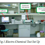 |
Figure 1: Electro-chemical test set up. |
Polarization Study: Samples were taken in an area of
0.204 square cm size coupons for performing potentiodynamic polarization studies in de-aerated condition in cells with three electrode configuration and using aqueous saturated calomel SCE (W) as the reference electrode and Pt foil as counter electrode. Linear s weep voltammetry was preformed with the help of AUTOLA B 12 PGSTAT , Eco Chemic B.V (the Netherlands ) at 0.5 mV/s s can rate within the potential range of -1500 mV to the cathodic potential of 650 mV vs .SCE. Potential s cans were conducted in de-aerated conditions by purging the s olution with nitrogen for 10min.Tafe l analys is was perfomed to determine the corros ion para meters .
Electro-chemical Impedance Spectroscopy: EIS at the res pective OCP value were recorded with the help of AUTO-LA B 12 PG STAT, Eco Chemie B.V (the Netherlands ) combined with frequency res pons e analyser (FRA) module.
The sinusoidal perturbation of 5mV amplitude was applied at the cell over the frequency range of 100 KHz to 10 MHz. EIS meas ure ments were conducted at open circuit conditions after a steady state potential was attained in the solution of diffe rent electrolytes at neutral pH. The experiment was performed in three electrode one compartment cell containing the test coupons as working electrode, a large area Pt foil as counter electrode and a s saturated calomel refe rence.
Result and Discussion
A. Micro structural Characteristic
Pre-corros ion microstructure for steel A1 and B1 reveals polygonal ferrite plus te mpered bainite and blocky polygonal ferrite plus tempe red bainite (as s hown in Fig.2 and Fig.3).
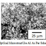 |
Figure 2: Opt ical microstruct ure A1 as per schedule 1 |
 |
Figure 3: Opt ical microst ruct ure B1 as per schedule 1. |
A2 and B2 reveals granular ferrite plus bainite and granular ferrite plus tempered bainite. A3 and B3 reveals accicular ferrite plus bainite and accicular ferrite. A4 and B4 s hows ferrite and martens ite. Finally A5 and B5 reveals ferrite and pearlite. Post corrosion microstructures, taken for a few samples for both steels, reveal adequate corrosion both in the form of grain boundary attack and pitting. However steel having high percentage of Cu and Cr, in case of steel B, this corrosion attack is comparatively less in all heat treatment schedules seemingly due to formation of protective oxide layer. Pos t corros ion micros tructures reveal adequate corros ion both in the form o f gra in boundary attack and pitting (as shown in Fig.4.and Fig.5 ).
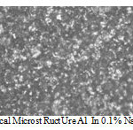 |
Figure 4: Opt ical microst ruct ure A1 in 0.1% NaCl ( 500X). |
However, s teels having high percentage of Cu and Cr (Steel B) face corros ion attack comparatively less in all heat treatment due to format ion of protective oxide layer.
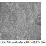 |
Figure 5: Opt ical microstructure B1 in 0.1% NaCl ( 500X ).
|
All the above mic ros tructure when s ubjected to image analys ing system (as s hown in Fig.6.and Fig.7).
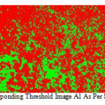 |
Figure 6: Corresponding threshold image A1 as per schedule 1.
|
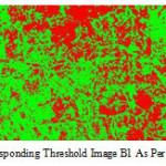 |
Figure 7: Corresponding threshold image B1 as per schedule 1. |
It is s een that high % of martens ite and/ or pearlite in ferrite matrix during water and a ir cooling
B. Corrosion Characteristic
Corros ion res ults have been s hown in Table III, Table IV& V
TABLE III
Corrosion Rate ( C R )
TABLE IV
Polaristion Resistance
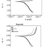 |
Figure 8: Polarisation plot for corrosion st udies in 0.1%. |
Corrosion Current
A2 and B2 in 0.1% Na Cl shows (as s hown in Fig.8 ) that B2 is characterized with a narrow but distinct passive region while in A2 there is no s uch region (as shown in Fig.9.A samples are more resistant than B samples Rp (A) > Rp (B) as shown in Table no-5. It may be predicted that matrix / grain boundary of A is more reactive than that of B in neutral conditions and that may be due to formation of thicker and stern passive layer (oxide film) in alloy B. This gets disrupted immediately in contact with Cl-. In most of A and B samples 10-fold decrease is observed when exposed to 0.1% NaCl. However this decrease is much restricted in case of B2 and B3 samples. With further increase in Cl- ion Rp decrease as usual.A more or less similar behavior is reflected with polarization studies.
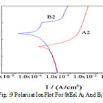 |
Figure 9: Polarisat ion plot for St eel A2 and B2 in 0.1% NaCl.
|
In neutral pH when EIS repres ents dual character A s a mples are more res istant than B samples .With further increase in Cl ion res is tance decreas e usual.Corros ion current /corros ion rate are much higher for A s amples then B ones .Interes tingly enough, in cas e of B2 and B3 s amp les corros ion rates are not that s ignificantly accelerated with Cl ion as in cas e of A s amples .EIS meas urement revea ls the Nyquis t plot (as s hown in Fig.10 and Fig.11) where ha lf circles diameter represent the circuit resistance of the material.
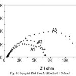 |
Figure 10: Nyquist plot for A st eel in 0.1% NaCl. |
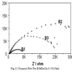 |
Figure 11: Nyquist plot for B st eel in 0.1% NaCl.
|
Concludion
The EIS is a powerful technique to inves tigate the corros ion protection of TRIP steel. Localized corros ion is a s erious problem of T RIP s teels when they are expos ed to chloride s olutions . As high-energy regions are prone to corros ion, micros tructure having finer grains , wh ich is more grain boundary, has les s corros ion res istance. Micros tructure contains more low temperature transformation products like bainite and/or martensite and other non equilibrium are more corrosion. Steel containing more Cu, Ni and Cr is less corros ive compared to other steels having same processing or micro-structure. Steels in rolled condition are more corros ive in both the case, probably due to high dislocation density. The retained austenite in non-Niobium steel is more stable, the non-Niobium steel has shown the optimum combination of mechanical properties.
Acknowledgement
The results presented in this paper were obtained within the project work o f M.Tech thesis in School of materials s cience and engineering, BESU, Shibpur, west Bengal. The authors would like to thank all the faculty me mbers of school of materials science and engineering and dept. of chemis try, BESU, Sh ibpur for fruitful help for this project. The authors would like to thank Head & Director, Prof.N.R.Bandhyopadhyay with all the faculty members of school of materials science and engineering and Prof.(Dr.) Jayati Datta ,dept. of chemistry, BESU, Shibpur for fruitful help for this project.
References
- Ultra light steel auto body-advanced vehicle technology (ULSAB-AVC) overview report,IISI,2002,p.66, www.worldautoteel.org. H. Gutte, A. Weiß, Metallurgical and Materials Transactions A (2010), submitted.
- J.NIEDBAŁA, Institute of Materials Science, University of Silesia, 40-007 Katowice, ul. Bankowa 12, Poland, Surface morphology and corrosion resistance of electrodeposited composite coatings containing polyethylene or polythiophene in Ni–Mo base, Bull. Mater. Sci., Vol. 34, No. 4, July 2011, pp. 993–996. © Indian Academy of Sciences.
- H. Berns, B. Hussong, S. Riedner, F. Wischnowski, Steel Research. 81 (2010) 3, 245–251.
- Sadhukhan, S., Das, K. P., Bandyopadhyay, N. R. and Banerjee, M. K. Journal of the Institution of Engineers, India, 82 (2001) 65.
- Bhadeshia, H. K. D. H. and Honeycombe, R. W. K. Steels: Microstructure and Properties, Elsevier, UK, (2006)
- V. F. Zackay, E. R. Parker, D. Fahr, and R. Busch, Transaction Quarterly, ASM. 60, 252, (1967).
- F. Blekkenhorst, G.M. Ferrari, C.J. van der Wekken and F.P. Ijsseling, Development of high strength low alloy, Brit. Corros. J. 21 3 (1986), pp. 163 –176.
- E.J. Czyryca, R.E. Link, R.J. Wong, D.A. Aylor, T.W. Montemarano and J.P . of HSLA -100 st eel for naval ship const ruct ion, Naval Engg J (1990), pp. 63–82 May.
- W.A. Schultze and C.J. vander Wekken, Influence of alloying Element s on t he marine corrosion of low alloy, Brit. Corros. J. 11 1 (1976), pp. 18–24.
- Oxidation of alloys involving noble metals, C.Wagner,and J.Elect rochem. Soc., 103, 571-580, (1956).
- D.D.N. Singh, A.K. Dey, Mahuya Dey and B.K. Singh, Corrosion (CORCORN ’97). I. Yu Konnva, T. K. Sergeeva, V. G. Gontmakher, N. A. P avienko, Sov. Mat. Sci.Rev., 3 1-4), (1989) 243
- Baorong Hou 1981 St udia Marine Sinica 1887 Bull. Mat er. Sci.Vol. 23 No. 3, June 2000, pp. 189–192. © Indian Academy of Sciences.189, Effect of alloy element s on the anti-corrosion properties
- of low alloy st eel, BAORONG HOU*, YANTAO LI, YANXU LI and JINGLEI ZHANG.
- Hou Baorong and Zhan g Jinglei 1980 Marine S ci. 4 16 Schumacher M 1979 Sea Water Corrosion hand book (New Jersey, USA: Noyes Dat a Corporat ion) p.12
- G.OISEN,”Computat ional Design of Hierarchically Struct ured
- Mat erials Science 277, 1237-1242 (1997)
- Int. J. Electrochem. Sci., 1(2006)171-180, Electrochemical Impedance Spectroscopy St udy of the Corrosion Behavior of Some Niobium Bearing St ainless St eels in 3.5% NaCl , Abdel Salam Hamdy1, E. El- Shenawy and T. El-Bitar. U. K. Mudali, P. Shankar, S. Ningshen, R.K. Dayal, H.S. Khat ak and Baldev Raj, Corros. Sci. 44 (2002) 2183.
- A.S. Hamdy, A.M. Beccaria and R. Spiniello, Corrosion Prevention & Control, 48(3) (2001)101

This work is licensed under a Creative Commons Attribution 4.0 International License.
![]()
A New Edition of Web of Science
Journal Impact Factor
2022: 0.5
Five Year: 0.8
Journal is Indexed in

Cabells Whitelist
![]()


