Modeling of Organic Mixtures Separation in Dense Membranes Using Finite Element Method (FEM).
Azam Marjani* and Saeed Shirazian
Islamic Azad University, Arak Branch, Department of Chemistry, Arak (Iran).
Article Received on :
Article Accepted on :
Article Published : 01 Mar 2012
A comprehensive mathematical model was developed to predict separation of organic mixtures using dense polymeric membranes. The organic mixture considered in this study was toluene and n-heptane mixture. The separation process was pervaporation (PV) which utilizes a dense membrane for separation. Conservation equations including continuity and energy transfers were solved numerically. Computational fluid dynamics (CFD) technique was used to solve the model equations. The toluene mole fraction and temperature profile were determined. The simulation results confirmed that the developed model can provide a general simulation for separation of organic mixtures using pervaporation.
KEYWORDS:Mass transfer; Membrane; CFD; Organic mixtures; Modeling
Download this article as:| Copy the following to cite this article: Marjani A, Shirazian S. Modeling of Organic Mixtures Separation in Dense Membranes Using Finite Element Method (FEM). Orient J Chem 2012;28(1). |
| Copy the following to cite this URL: Marjani A, Shirazian S. Modeling of Organic Mixtures Separation in Dense Membranes Using Finite Element Method (FEM). Available from: http://www.orientjchem.org/?p=11795 |
Introduction
Nowadays, membrane technology has become one of the effective technologies with wide applications. One of the membrane processes is pervaporation (PV) which is used for separation of liquid mixtures. Pervaporation is a membrane-based separation process that has gained much interest by the chemical industry as an effective and energy-efficient technology to carry out separations that are difficult to achieve by conventional processes such as distillation, extraction or adsorption. Pervaporation is more favorable for azeotropic and close-boiling liquid mixture separation; organic solvent dehydration and recovery of high added-value dilute species from water [1-10]. The transport of species through the PV membranes involves three steps in series: (A) selective sorption into the membrane, (B) diffusion through the membrane, and (C) desorption into the vapor phase. The mass transport rate of overall process is functions of solubility and diffusivity, since the desorption step is fast due to the efficient vacuum [11-15].
Separation of aromatic/aliphatic hydrocarbon mixtures is an important process in chemical and petrochemical industries. This is also categorized as a major branch of organic/organic mixtures separation. This field was first investigated 25 years ago, in the frame of a European project [5, 6]. The application of this separation is in production of aromatic-lean motor fuels that are recommended in developed countries [8, 15-20].
Modeling of pervaporation is of vital importance for designing and optimizing the process. It is necessary to develop a comprehensive model which can predict transport of species in PV process. The main purpose of this work is to develop and solve a mathematical model for simulation of toluene/n-heptane mixtures separation by pervaporation. Simulations are based on solving the conservation equations including mass and energy transfer of toluene and n-heptane in the feed side, the membrane and the permeate side.
Mathematical modeling of the process
The following assumptions are considered for developing the mathematical model [15-20]:
Solution-diffusion model was used to describe solute transport.
Thermodynamic equilibrium was assumed at the feed-membrane interface.
Physical properties of the permeate vapor were considered as air at very low pressure.
The equation of mass transfer
The continuity equation is the main equation that describes the transfer of toluene and n-heptane from the feed side to the permeate side and it is derived from mass balance of components. Equation 1 is the continuity equation. The continuity equation should be solved numerically to obtain the concentration distribution of toluene and n-heptane in the membrane module. This equation is obtained using Fick’s law of diffusion for estimation of diffusive flux [20]:
![]()
where c is the concentration (mol/m3), D is diffusion coefficient (m2/s), u is the velocity vector (m/s), R is the reaction rate (mol/m3.s) which is not considered in the calculations and δts is the time-scaling coefficient.
The equation of energy transfer
Equation 2 is the general energy transfer equation and should be solved numerically to obtain the temperature distribution of toluene and n-heptane in the membrane module. This equation includes both term of conduction and convection energy transfer [20]:
![]()
Cp is the heat capacity at constant pressure (J/kg.K), is the thermal conductivity (W/m.K), is the heat source (W/m3), is the production/absorption coefficient (W/m3.K), u is the velocity vector (m/s), r is the density of the fluid (kg/m3).
Numerical solution of the model equations
The governing equations with the appropriate boundary conditions were solved numerically using COMSOL Multiphysics software version 3.2. This software employs finite element method (FEM) in numerical solving of the model equations. The use of FEM method allows mass conservation in the domain; therefore “numerical loss” of mass in the computational domain is not a major concern. The applicability, validity and robustness of the FEM method for the kind of domain encountered in the present work were proved by a number of previous authors [20-25]. The FEM was combined with adaptive meshing and error control using numerical solver of UMFPACK. This solver is an implicit time-stepping scheme, which is well suited for solving stiff and non-stiff non-linear boundary value problems [25]. An IBM-PC-Pentium 5 (CPU speed was 2600 MHz and 2 GB of RAM) was used to solve the set of equations.
Results and discussion
Profile of toluene mole fraction
Fig. 1 shows mole fraction profile of toluene in the membrane module. As it is seen from the figure, near the membrane surface, toluene mole fraction decreases. This could be due to the fact that the membrane is aromatic (toluene) selective and toluene molecules tend to be absorbed to the membrane and pass through the membrane. As observed, the toluene diffusion through the membrane follows a steady trend, while at the module outlet because of the applied vacuum, toluene mole fraction gradient increase to supply toluene in the permeate stream.
As the feed is poured into the module, toluene is transferred to the membrane due to its concentration difference which is the driving force of process. The dominant mechanism of mass transfer in the feed side of the module is diffusion because the process is assumed to be batch. The mass (toluene) is transferred through the dense membrane via diffusion mechanism. Toluene after passing through the membrane which is transferred only by diffusion mechanism is then evaporated by the induced vacuum in the permeate side.
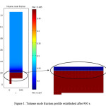 |
Figure 1: Toluene mole fraction profile established after 900 s. Click here to View figure |
Mole fraction profile of toluene along the PV module at different times is indicated in Fig. 2. As it is seen, in the beginning of process and before nearly steady state condition, toluene mole fraction varies within the time but after 900 s running the experiment and attaining nearly steady state condition, toluene mole fraction becomes constant. In addition, in the feed side, toluene mole fraction is constant and near the membrane an instant decrease is observed and in the permeate side mole fraction reaches the constant value.
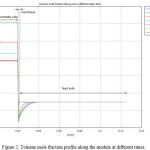 |
Figure 2: Toluene mole fraction profile along the module at different times. Click here to View figure |
Temperature profile
By solving the conductive-convective energy transfer, the temperature profile in the PV module was obtained. Fig. 3 shows the temperature profile in the module after 900 s and attaining nearly steady state condition. However, it needs more computational time for being steady state and according to pervious section at 900 s have steady result for mole fraction (concentration). As observed, near the module wall, because of direct contact with heat source, temperature has its highest value and this value decreases in the middle of the module. In the membrane zone, which is between the feed and the permeate side, the slop of temperature profile changes. This phenomenon may be due to the phase conversion from liquid phase in the feed to vapor phase in the permeate at two sides of the membrane. In addition, the conductive and convective heat transfer is faster in vapor phase rather than liquid one, hence, the temperature profile exhibits different trends in this phase change.
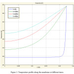 |
Figure 3: Temperature profile along the membrane at different times. Click here to View figure |
Conclusions
In this work, separation of toluene from n-heptane by pervaporation using a dense polymeric membrane was studied theoretically. A comprehensive 2-dimensional mathematical model was developed to predict unsteady state transport of toluene and n-heptane through the membrane in a PV batch system. The model was based on numerical solving of the conservation equations (continuity and energy transfer) for the components in the membrane module. The modeling results also presented toluene mole fraction profile and temperature profile in the module and near the membrane surface. The simulation results described that the developed model could provide a general simulation of transport in the PV process.
References
- Feng, X.; Huang, Y. M. Liquid separation by membrane pervaporation: a review. Ind. Eng. Chem. Res. 36 (1997) 1048-1066.
- V.S. Cunha, M.L.L. Paredes, C.P. Borges, A.C. Habert, R. Nobrega, Removal of aromatics from multicomponent organic mixtures by pervaporation using polyurethane membranes: experimental and modeling, J. Membr. Sci. 206 (2002) 277-290.
- M.Y. Teng, Ch.L. Li, K. R. Lee, J. Y. Lai, Permselectivities of 3,3′,4,4′ benzhydrol tetraacarboxylic dianhydride based polyimide membrane for pervaporation, Desalination 193 (2006) 144-151.
- J. Frahn, G. Malsch, H. Matuschewski, U. Schedler, H.H. Schwarz, Separation of aromatic/aliphatic hydrocarbons by photo-modified poly(acrylonitrile) membranes, J. Membr. Sci. 234 (2004) 55-65.
- M. Yoshikawa, H. Shimada, H. Tsubouchi, Y. Kondo, Specialty polymeric membranes, 12. Pervaporation of benzene–cyclohexane mixtures through carbon graphite–nylon 6 composite membranes, J. Membr. Sci. 177 (2000) 49-53.
- B. Smitha, D. Suhanya, Sridhar S., Ramakrishna M., Separation of organic-organic mixtures by pervaporation- a review, J. Membr. Sci. 241 (2004) 1-21.
- P. Steltenpohl, M. Chlebovec, E., Graczova, Simulation of Toluene Extractive Distillation from a Mixture with Heptane, Chem. Pap. 59 (2005) 421-427.
- P. Billard, Q.T. Nguyen, C. Leger, R. Clement, Diffusion of organic compounds through chemically asymmetric membranes made of semi-interpenetrating polymer networks, Sep. Purif. Technol. 14 (1998) 221-232.
- M.A. Hughes, Y. Haoran, Liquid-Liquid Equilibria for Separation of Toluene from Heptane by Benzyl Alcohol Tri( ethylene glycol) Mixtures, J. Chem. Eng. Data 35 (1990) 967-971.
- G.W. Meindersma, T. van Schoonhoven, B. Kuzmanovic, A.B. de Haan, Extraction of toluene, o-xylene from heptane and benzyl alcohol from toluene with aqueous cyclodextrins, Chem. Eng. Process. 45 (2006) 175–183.
- M. Mohsen-Nia, F.S. Mohammad Doulabi, Separation of aromatic hydrocarbons (toluene or benzene) from aliphatic hydrocarbon (n-heptane) by extraction with ethylene carbonate, J. Chem. Thermodyn. 42 (2010) 1281-1285.
- J. Garcia, S. Garcia, J.S. Torrecilla, M. Oliet, F. Rodriguez, Separation of toluene and heptane by liquid–liquid extraction using z-methyl-N-butylpyridinium tetrafluoroborate isomers (z = 2, 3, or 4) at T = 313.2 K, J. Chem. Thermodyn. 42 (2010) 1004–1008.
- J.P. Garcia Villaluenga, A. Tabe-Mohammadi, A review on the separation of benzene/cyclohexane mixtures by pervaporation processes, J. Membr. Sci. 169 (2000) 159–174.
- A.V. Koselev, V.V. Khopina, L.A. El’tekov, Adsorption of toluene-heptane mixtures on silica gels and carbon blacks, Russ. Chem. Bull. 7 (1958) 647-653.
- Q. Huang, H. Vinh-Thang, A. Malekian, M. Eic, D.Trong-On, S. Kaliaguine, Adsorption of n-heptane, toluene and o-xylene on mesoporous UL-ZSM5 materials, Microporous Mesoporous Mater. 87 (2006) 224-234.
- M. Matsumoto, Y. Inomoto, K. Kondo, Selective separation of aromatic hydrocarbons through supported liquid membranes based on ionic liquids, J. Membr. Sci. 246 (2005) 77-81.
- M. Chakraborty, M. Bart , Highly selective and efficient transport of toluene in bulk ionic liquid membranes containing Ag+ as carrier, Fuel Process. Technol. 88 (2007) 43-49.
- M. Chakraborty, H.J. Bart , Emulsion liquid membranes: Role of internal droplet size distribution on toluene/n-heptane separation, Colloids Surf., A. 272 (2006) 15-21.
- H. Schwarz, G.Malsch, Polyelectrolyte membranes for aromatic–aliphatic hydrocarbon separation by pervaporation, J. Membr. Sci. 247 (2005) 143-152.
- Shirazian, S., A. Moghadassi, and S. Moradi, Numerical simulation of mass transfer in gas-liquid hollow fiber membrane contactors for laminar flow conditions. Simulation Modelling Practice and Theory, 2009. 17 (4): p. 708-718.
- D. Roizard, D. Nilly, P. Lochon, Preparation and study of crosslinked polyurethane films to fractionate toluene–n-heptane mixtures by pervaporation, Sep. Purif. Technol. 22-23 (2001) 45-52.
- H. Ye, J. Li, Y. Lin, J. Chen, Synthesis of Polyimides Containing Fluorine and Their Pervaporation Performances to Aromatic/Aliphatic Hydrocarbon Mixtures, J. Macromol. Sci., Part A: Pure Appl. Chem. 45 (2008) 172-178.
- F.V. Ackern, L. Krasemann, B. Tieke, Ultrathin membranes for gas separation and pervaporation prepared upon electrostatic self-assembly of polyelectrolytes, Thin Solid Films 327-329 (1998) 762-766.
- L. Zhen, W. Yingying, L. Shiqing, Y. Bolun, Ultrathin membranes for gas separation and pervaporation prepared upon electrostatic self-assembly of polyelectrolytes, Chin. J. Chem. Eng. 16-1 (2008) 79-83.
- S. Shirazian, S.N. Ashrafizadeh, Mass Transfer Simulation of Carbon Dioxide Absorption in a Hollow-Fiber Membrane Contactor, Sep. Sci. Technol. 45 (2010) 515 – 524.

This work is licensed under a Creative Commons Attribution 4.0 International License.
![]()
A New Edition of Web of Science
Journal Impact Factor
2022: 0.5
Five Year: 0.8
Journal is Indexed in

Cabells Whitelist
![]()


