Mathematical Modeling of Gas Separation in Flat-sheet Membrane Contactors
Azam Marjani¹*, Saeed Shirazian¹, Mahmoud Ranjbar¹ and Mitra Ahmadi²
¹Islamic Azad University, Arak Branch, Department of Chemistry, Arak (Iran).
²Department of Chemical Engineering, University of Payam Noor, Tehran (Iran).
Article Received on :
Article Accepted on :
Article Published : 01 Mar 2012
Gas-liquid membrane contactors offer several practical advantages including high surface area per unit volume; independent control of gas and liquid velocities without any flooding, loading, weeping, or foaming, pre-determined gas–liquid interfacial area, membrane modules, capability of linear scale-up; low corrosion problems, and low operation and capital costs. Two common types of membrane contactors are extensively utilized for gas separation. However, most studies have focused on the hollow-fiber membrane contactors. The main advantage of flat-sheet membrane contactors is that not only any type of membrane can be formed into flat-sheet membrane module but also fabrication of flat-sheet membranes is also easier compared to other types of membranes. A mass transfer model was developed in this study to investigate the performance of flatsheet membrane contactors for gas absorption. The model was based on the behavior of gas and liquid phases in the membrane contactor by taking the distribution of gas concentration as well as the gas and liquid velocity profiles along the flowing direction into account. Both chemical and physical absorptions were considered. The model also uses computational fluid dynamics of mass and momentum transfer in both gas and liquid phases in the membrane contactor. An appropriate numerical method based on the finite element method was applied to solve the model equations. The model predictions were validated against the experimental data obtained from literature for the absorption of CO2 . The results were in good agreement with the experimental data with different values of flow rates. The model predictions indicated that the removal of CO2 was increased with increasing the liquid velocity in the membrane contactor. On the other hand, increasing temperature and gas velocity in the flat-sheet membrane contactor showed an opposite effect on the removal of CO2 . It is indicated that the proposed model well predicts the mass transfer within the flat-sheet membrane contactors.
KEYWORDS:Membrane Contactor; Gas Absorption; Mass Transfer; Modeling; CFD
Download this article as:| Copy the following to cite this article: Marjani A, Shirazian S, Ranjbar M, Ahmadi M. Mathematical Modeling of Gas Separation in Flat-sheet Membrane Contactors. Orient J Chem 2012;28(1). |
| Copy the following to cite this URL: Marjani A, Shirazian S, Ranjbar M, Ahmadi M. Mathematical Modeling of Gas Separation in Flat-sheet Membrane Contactors. Available from: http://www.orientjchem.org/?p=11781 |
Introduction
Current carbon dioxide removal technologies are based on a variety of physical and chemical processes such as adsorption, absorption, cryogenic and membrane contactors [1]. Conventional processes for the removal of CO2 suffer from many problems such as entraining, channeling, flooding, foaming and high capital and operating costs [2]. Many researchers have examined the possibilities of increasing the efficiency of these processes to reduce the effect of their problems. Gas-liquid membrane contactors are expected to solve the disadvantages of the conventional processes when incorporated into the gas treating processes [1]. The characteristic of gas-liquid membrane contactors is that the gas stream flows on one side and the absorbent liquid flows on the other side of the membrane without phase dispersion, thus avoiding the problems often encountered in the conventional equipment such as foaming, flooding, channeling and entrainment [2].
Experiments and theories about the gas-liquid membrane contactors had been done since Zhang and Cussler first studied the work [3]. Using polypropylene membrane, Kreulen et al. [4] studied absorption of CO2 into water/glycerol mixtures. The authors studied the membrane as gas–liquid contactors in the case of both physical and chemical absorption.
There is a definite need for a mass transfer model that can provide a general simulation of the chemical and physical absorption of gases in gas-liquid flat sheet membrane contactors. The main purpose of this study is to solve a 2D mathematical model for the absorption of CO2 in flat sheet membrane contactors. The model is then validated using experimental data obtained from literature for the absorption of CO2 in water. Influence of different process parameters will be investigated on the mass transfer and absorption of CO2 in the membrane contactor.
Theory
A comprehensive two-dimensional mathematical model was used for the transport of carbon dioxide through flat sheet membrane contactors. In this work, the absorption of CO2 from CO2/N2 gas mixture in pure water is studied in a flat sheet membrane contactor. The model was based on “non-wetted mode” in which the gas phase filled the membrane pores for co-current gas–liquid contacts. Laminar velocity distributions are used for the gas and liquid flow in the membrane contactor.
Model equations
A 2D mass transfer model was used for a flat sheet membrane, as shown in Fig. 1. The gas flows with a fully developed laminar velocity in one side and the liquid absorbent (pure water) flows with laminar flow in the other side. Fig. 1 shows the cross sectional area of the flat sheet membrane contactor. The steady state two-dimensional mass balances are carried out for the membrane contactor. The gas phase is fed to the one side (at z = 0), while the absorbent is passed through the other side (at z = 0). Carbon dioxide is removed from the gas mixture by diffusing through the membrane and then is absorbed in the solvent (water).
The assumptions made in developing this model are as follows:
Steady state and isothermal conditions.
Fully developed gas and liquid velocity profile in the flat sheet membrane.
Ideal gas behavior is imposed.
The Henry’s law is applicable for gas-liquid interface.
Laminar flow for gas and liquid flow in the membrane contactor.
Non-wetted mode in which the gas filled the membrane pores.
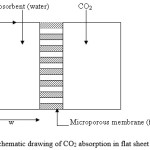 |
Figure 1: Schematic drawing of CO2 absorption in flat sheet membrane. Click here to View figure |
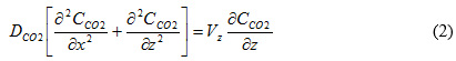
The continuity equation for each species in a reactive absorption system can be expressed as [5]:
![]()
where Ci, Ji, Ri, V and t are the concentration, diffusive flux, reaction rate of species i, velocity and time, respectively. Either Fick’s law of diffusion or Maxwell–Stefan theory can be used for the calculation of diffusive fluxes of species i [2].
The continuity equation for steady state for CO2 in the three sections of flat sheet membrane contactor is obtained using Fick’s law of diffusion for estimation of diffusive flux:
In a laminar flow, a fully developed velocity profile can be described as [5]:
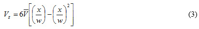
where is the average velocity in the flat sheet membrane.
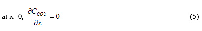
The boundary conditions for mass transfer equations are:
at z=0, CCO2=C0 (4)
at x=w, CCO2=CCO2,gas×m (6)
where m is the physical solubility of CO2 in the liquid absorbent (pure water).
Method of numerical solution
The model equations with the appropriate boundary conditions were solved using COMSOL Multiphysics software, which uses finite element method (FEM) for numerical solutions of differential equations. The finite element method (FEM) is combined with adaptive meshing and error control using numerical solver of UMFPACK. The meshed geometry is illustrated in Fig. 2.
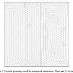 |
Figure 2: Meshed geometry used for numerical simulation. There are 2336 meshes. Click here to View figure |
Results and discussion
The inlet concentration of CO2 in CO2/N2 mixture is taken 10 mol/m3. The total gas phase concentration was assumed constant in the calculations. The length of the membrane considered in this work, is 0.8 m and the distance between the contactor wall and the membrane is 0.02 m. The physical solubility ( ) of CO2 in pure water and the diffusion coefficient of CO2 in the water and N2 were obtained from the literatures [6, 7].
Concentration distribution of CO2 in the gas phase
Physical absorption of CO2 in pure water using a flat sheet membrane contactor is simulated here. The flat sheet membrane geometry and operating parameters used in the simulation are the same as those used by Wang et al. [8].
Fig. 3 presents 2-dimensional concentration distribution of CO2 in the gas phase of flat sheet membrane contactor. The gas phase flows from one side of the membrane, i.e. at z = 0 where the concentration of carbon dioxide is the maximum. Water passes inside the other side co-currently. Fig. 4 also indicates axial concentration distribution of CO2 in the gas phase.
As the feed flows through the membrane contactor, CO2 is transferred toward the membrane pores due to concentration difference between the bulk and the membrane surface. Concentration difference is the driving force for mass transfer of carbon dioxide into the membrane.
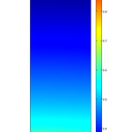 |
Figure 3: 2D concentration distribution of CO2 in the gas phase. Vg=0.001 m/s, Vl=0.1 m/s, C0=10 mol/m3. Click here to View figure |
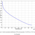 |
Figure 4: Axial concentration distribution of CO2 in the gas phase. Vg=0.001 m/s, Vl=0.1 m/s, C0=10 mol/m3. Click here to View figure |
Concentration distribution of CO2 in the liquid phase
Concentration distribution of CO2 in the liquid phase is illustrated in Figs. 5 & 6. Fig. 5 shows the surface distribution and Fig. 6 shows the curve of concentration in x direction at the middle of membrane contactor. The transport of carbon dioxide from the gas phase into the liquid phase involves two mechanisms, diffusion and convection. The convection contribution depends on the velocity of fluid or media.
Figs. 5 & 6 also indicate that in the regions near the membrane wall, concentration change is great. This is the evidence for formation of concentration boundary layer.
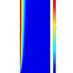 |
Figure 5: 2D concentration distribution of CO2 in the liquid phase. Vg=0.001 m/s, Vl=0.001 m/s, C0=10 mol/m3. Click here to View figure |
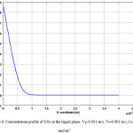 |
Figure 6: Concentration profile of CO2 in the liquid phase. Vg=0.001 m/s, Vl=0.001 m/s, C0=10 mol/m3. Click here to View figure |
Distribution of CO2 mass transfer flux
Variations of the mass transfer flux of CO2 in the gas phase are indicated in Fig. 7. The mass transfer fluxes are illustrated by arrows in Fig. 7. The mass transfer flux is summation of diffusional and convection flux of CO2 in the feed side. It is clearly shown that in the regions near the axis of the feed i.e., x = 0 the total flux is higher than other regions. This is due to high convection mass transfer in these regions. In fact, velocity which causes convection mass transfer is more significant in the z-direction.
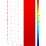 |
Figure 7: Arrows of total flux in the gas phase and concentration distribution of CO2 inside the membrane. Vg=0.0003 m/s, Vl=0.001 m/s, C0=10 mol/m3. Click here to View figure |
Conclusions
This work presents a numerical simulation of mass transfer in a flat sheet membrane contactor for a gas–liquid process. The numerical simulation was based on solving the conservation equations for gas in the membrane contactor. The influence of various process parameters on the mass transfer of CO2 was investigated. The results for the physical absorption of CO2 into water indicated that the developed model is capable of predicting mass transfer in the gas-liquid flat sheet membrane contactors.
References
- Shirazian, S., A. Moghadassi, and S. Moradi, Numerical simulation of mass transfer in gas-liquid hollow fiber membrane contactors for laminar flow conditions. Simulation Modelling Practice and Theory, 2009. 17 (4): p. 708-718.
- Saeed Shirazian, Azam Marjani, Farzad Fadaei, Supercritical extraction of organic solutes from aqueous solutions by means of membrane contactors: CFD simulation, Desalination, Volume 277, Issues 1-3, 2011, Pages 135-140.
- Azam Marjani, Saeed Shirazian, Simulation of heavy metal extraction in membrane contactors using computational fluid dynamics, Desalination, Volume 281, 2011, Pages 422-428.
- Saeed Shirazian, Azam Marjani, Fatemeh Azizmohammadi, Prediction of SO2 Transport Across Ceramic Membranes Using Finite Element Method (FEM), Oriental journal of Chemistry Volume No. 27 Issue No.: 2 Page No. 485-490.
- Mahmoud Reza Sohrabi, Azam Marjani, Sadegh Moradi, Mehran Davallo, Saeed Shirazian, Theoretical Studies on Membrane-Based Gas Separation using Computational Fluid Dynamics (CFD) of Mass Transfer, Journal of the Chemical Society of Pakistan Vol. 33 No. 4, pp. 464-473, 2011.
- Mahmoud Reza Sohrabi, Azam Marjani, Sadegh Moradi, Mehran Davallo, Saeed Shirazian, Mathematical modeling and numerical simulation of CO2 transport through hollow-fiber membranes, Applied Mathematical Modelling 35 (2011) 174–188.
- Mahmoud Reza Sohrabi, Azam Marjani, Saeed Shirazian, Sadegh Moradi, Acetone and Ethanol Extraction from Water by Means of Membrane: Modeling and Numerical Simulation, Middle-East Journal of Scientific Research 7 (4): 530-537, 2011.
- Wang, W.P., Lin, H.T., Ho, C.D., An analytical study of laminar co-current flow gas absorption through a parallel-plate gas–liquid membrane contactor, Ind. Eng. Chem. Res. 2006; 278: 181.

This work is licensed under a Creative Commons Attribution 4.0 International License.
![]()
A New Edition of Web of Science
Journal Impact Factor
2022: 0.5
Five Year: 0.8
Journal is Indexed in

Cabells Whitelist
![]()


