Mathematical Modeling and Numerical Simulation of Wastewater Treatment Unit Using CFD
Mahboobeh Pishnamazi¹, Azam Marjani², Saeed Shirazian²* and Mohammad Samipurgiri³
¹Petroleum Engineering Department, Iranian Central Oil Fields Company (ICOFC), Tehran (Iran). ²Islamic Azad University, Arak Branch, Department of Chemistry, Arak (Iran). ³Islamic Azad University, Tehran North Branch, Department of Chemical Engineering, Tehran (Iran).
Article Received on :
Article Accepted on :
Article Published : 01 Mar 2012
This paper presents mathematical modeling and numerical simulation of hydrodynamics of a mixer used for wastewater treatment. The simulation is based on solving conservation equations for mixer. Swirl flow is considered for flow behavior in the mixer. The geometry of mixer was divided in to subdomains including fixed and mobile parts. Impeller was considered as mixing device. The model equations are solved by using computational fluid dynamics (CFD) techniques. Velocity distributions were obtained through solving the governing equations. The simulations results showed that there are some dead zones which reduce the efficiency of the mixing process. The modeling findings also revealed that velocity of impeller is a key parameter for increasing mixing efficiency.
KEYWORDS:Mixer; Wastewater treatment; CFD; Simulation; Modeling
Download this article as:| Copy the following to cite this article: Pishnamazi M, Marjani A, Shirazian S, Samipurgiri M. Mathematical Modeling and Numerical Simulation of Wastewater Treatment Unit Using CFD. Orient J Chem 2012;28(1). |
| Copy the following to cite this URL: Pishnamazi M, Marjani A, Shirazian S, Samipurgiri M. Mathematical Modeling and Numerical Simulation of Wastewater Treatment Unit Using CFD. Available from: http://www.orientjchem.org/?p=11801 |
Introduction
Nowadays, wastewater treatment is of vital importance in all industries. It can be defined as the process of removing contaminants from industrial and municipal wastewater. Wastewater treatment can be carried out using physical, chemical, and biological processes to remove physical, chemical and biological contaminants from water. Its objective is to produce an environmentally-safe fluid waste stream (or treated effluent) and a solid waste (or treated sludge) suitable for disposal or reuse. Using advanced technology it is now possible to re-use sewage effluent for drinking water.
Biological wastewater treatment is the most important and applicable process for wastewater treatment. It includes some processes and operations. Mixer is the most important equipment used in biological wastewater treatment. Mixers play crucial role in optimizing and improvement of whole treatment process. Modeling and simulation of mixers is the best method for designing and optimization of these devices. Modeling can be carried out by solving conservation equations including mass, momentum and energy equations. The main purpose of this work is to develop and solve a comprehensive mathematical model for simulation of fluid flow in a mixer. The governing equations are solved numerically using CFD based on finite element method (FEM). Velocity and pressure distributions are obtained and evaluated to find the optimum conditions [1-5].
Model equations
A 3D comprehensive mathematical model is developed for simulation of flow in a mixer of wastewater treatment unit. The model is built considering following assumptions:
Isothermal condition is assumed
Incompressible fluid inside the mixer
Newtonian fluid
Physical properties such as viscosity and density are assumed to be constant
Swirl flow is considered for flow behavior inside the mixer
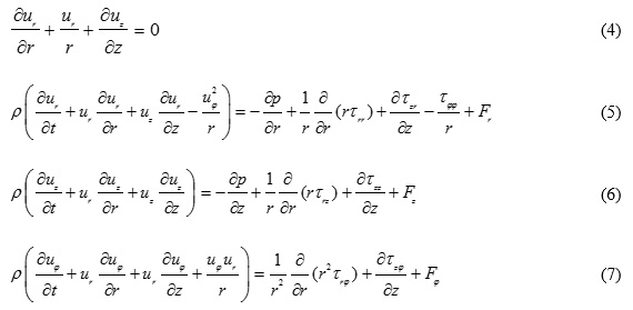
The general equations describing flow behavior in the mixer are the Navier-Stokes equations and can be expressed as follows:
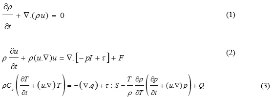
The tensors of stress applied in these equations may be written as follows:
Numerical simulation
Geometry of the mixer
The first step for numerical solution of the governing equations is drawing the geometry of mixer. The mixer studied in this work is constituted of two parts, i.e. fixed and mobile parts. The fixed part is the wall of mixer and the mobile part is the impeller which makes the swirl flow. These two parts are shown in Fig. 1. As it can be seen, there are also four baffles in the fixed parts of the mixer. These baffles increase the efficiency of mixing process by removing dead zone parts.
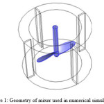 |
Figure 1: Geometry of mixer used in numerical simulation. |
Meshing is also required to divide the model domain into small parts for numerical solution. Numerical solution of the governing equations is applied in each mesh. The meshed geometry is shown is Fig. 2. The meshes are created using Comsol Multiphysics 4.2 software.
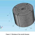 |
Figure 2: Meshing of the model domain. |
Numerical solution
The main objective of the present study is to model a mixer using CFD of momentum transfer. The equations of mixer with appropriate boundary conditions were solved using COMSOL Multiphysics version 4.2 software (Sweden), which uses finite element method (FEM) for numerical solution of the equations. The finite element analysis is combined with adaptive meshing and error control using numerical solver of UMFPACK. This solver is well suited for solving stiff and non-stiff non-linear boundary value problems. The applicability, robustness and accuracy of this method have been proved through distinct researches [6-10]. It should be pointed out that the COMSOL mesh generator creates triangular meshes that are isotropic in size. A large number of elements are then created with scaling. A scaling factor was employed for the mixer. COMSOL automatically scales back the geometry after meshing. Adaptive mesh refinement in COMSOL, which generates the best and minimal meshes, was used to mesh the mixer geometry. The algorithm which was developed for the numerical simulation is shown in Fig. 3. An IBM-PC-Pentium 4 (CPU speed is 2800 MHz) was used to solve the sets of equations.
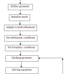 |
Figure 3: Algorithm developed for numerical simulation. |
Results and discussion
Velocity distribution
The main parameter for simulation of mixer is the velocity of fluid inside the mixer. The objective of the current simulation was to determine the velocity vector of during mixing process in the mixer. The mixer is applied for wastewater treatment units. The 3D velocity distribution of fluid inside the mixer is shown in Fig. 4. The velocity in the mixer is shown at three different slices. Figs. 5 & 6 also indicate the velocity profile as curves. As it can be seen from the figures, the maximum of velocity is observed at the regions near the impeller. On the other hand, the velocity near the mixer’s wall is zero which implies that no-slip condition is imposed at this boundary.
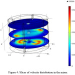 |
Figure 4: Slices of velocity distribution in the mixer. |
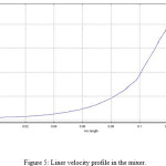 |
Figure 5: Liner velocity profile in the mixer. |
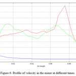 |
Figure 6: Profile of velocity in the mixer at different times. |
Conclusions
A 3D mathematical model was developed in this work to simulate the flow in a mixer of wastewater treatment unit. The model solves equations of swirl flow. Finite element method (FEM) was applied for numerical solution of the swirl flow equations. Comsol Multiphysics software was used for numerical simulation. Velocity distributions were obtained and indicated that there are some dead zones near the wall of mixer which can be removed by adjusting the impeller velocity. The impeller can also change the flow pattern. The results of this work confirmed that the developed model is capable of simulation of flow in mixers for different geometries.
References
- Shirazian, S., A. Moghadassi, and S. Moradi, Numerical simulation of mass transfer in gas-liquid hollow fiber membrane contactors for laminar flow conditions. Simulation Modelling Practice and Theory, 2009. 17 (4): p. 708-718.
- Shirazian, S. and S.N. Ashrafizadeh, Mass Transfer Simulation of Caffeine Extraction by Subcritical CO2 in a Hollow-Fiber Membrane Contactor. Solvent Extraction and Ion Exchange, 2010. 28 (2): p. 267 – 286.
- Shirazian, S. and S.N. Ashrafizadeh, Mass Transfer Simulation of Carbon Dioxide Absorption in a Hollow-Fiber Membrane Contactor. Separation Science and Technology, 2010. 45 (4): p. 515 – 524.
- Shirazian, S. and S.N. Ashrafizadeh, Near-Critical Extraction of the Fermentation Products by Membrane Contactors: A Mass Transfer Simulation. Industrial & Engineering Chemistry Research, 2011. 50(4): p. 2245-2253.
- Farzad Fadaei, Saeed Shirazian, Seyed Nezameddin Ashrafizadeh, Mass transfer simulation of solvent extraction in hollow-fiber membrane contactors , Desalination, Volume 275, Issues 1-3, 2011, Pages 126-132.
- Saeed Shirazian, Azam Marjani, Farzad Fadaei, Supercritical extraction of organic solutes from aqueous solutions by means of membrane contactors: CFD simulation, Desalination, Volume 277, Issues 1-3, 2011, Pages 135-140.
- Azam Marjani, Saeed Shirazian, Simulation of heavy metal extraction in membrane contactors using computational fluid dynamics, Desalination, Volume 281, 2011, Pages 422-428.
- Saeed Shirazian, Azam Marjani, Fatemeh Azizmohammadi, Prediction of SO2 Transport Across Ceramic Membranes Using Finite Element Method (FEM), Oriental journal of Chemistry Volume No. 27 Issue No.: 2 Page No. 485-490.
- Brucato, A., Ciofalo, M., Grisafi, F., and Micale, G., Numerical prediction of flow fields in baffled stirred vessels: a comparison of alternative modelling approaches, Chem. Eng. Sci., No. 53, pp. 3653-3684, 1998.
- Mavros, P., Flow visualization in stirred vessels-a review of experimental techniques, Trans. Inst. Chem. Eng. Part A Chem. Eng. Res. Des., No. 79, pp. 113-127, 2001.

This work is licensed under a Creative Commons Attribution 4.0 International License.
![]()
A New Edition of Web of Science
Journal Impact Factor
2022: 0.5
Five Year: 0.8
Journal is Indexed in

Cabells Whitelist
![]()


