Studies on Polymeric Hydroxy Compounds and the Electro-Coagulation Process for Removing Arsenic from Ground Water
1Department of Basic Science and Humanities, Pranveer Singh Institute of Technology, Kanpur-209305.
2Department of Chemistry, School of Applied and Life Sciences, Uttaranchal University, Dehradun-248007.
Corresponding Author E-mail: anuragtewari70@gmail.com
DOI : http://dx.doi.org/10.13005/ojc/380613
Article Received on : 25 Oct 2022
Article Accepted on :
Article Published : 28 Nov 2022
Reviewed by: Dr. Tasneem Mohammed
Second Review by: Dr. Ioana Stanciu
Final Approval by: Dr. Ayssar Nahle
This paper describes observations made on studies carried in laboratory trials by using electro-coagulation process using iron electrodes. The purpose of this study is to present the iron electrode-based EC procedure, its superiority over other technologies used for removing arsenic from ground water and surface water. In order to reduce arsenic (As), it was also necessary to understand the basics of the electrochemical process (EC) and the significance of its operating conditions, such as anode materials, applied voltage, pH and anode distance. At different concentration of Arsenic (500ppb, 200ppb & 100 ppb) it was observed that with the higher concentration i.e. 500 ppb there is faster decrease in arsenic concentration at 6.5 pH. While, when using different current density 0.5 A & 1.0 A at (12V) almost same results were obtained i.e. arsenic removal took place in same time duration at a pH range of 3.5 to 6.5. It was also observed that arsenic concentration decreases with electrode spacing, size of electrodes and contact time of treatment.
KEYWORDS:Arsenic; Contamination; Electrodes; Electro-coagulation; Ground water
Download this article as:| Copy the following to cite this article: Tewari A, Paroha P. P, Awasthi S. Studies on Polymeric Hydroxy Compounds and the Electro-Coagulation Process for Removing Arsenic from Ground Water. Orient J Chem 2022;38(6). |
| Copy the following to cite this URL: Tewari A, Paroha P. P, Awasthi S. Studies on Polymeric Hydroxy Compounds and the Electro-Coagulation Process for Removing Arsenic from Ground Water. Orient J Chem 2022;38(6). Available from: https://bit.ly/3EZHb9L |
Introduction
Arsenic (As) occurs naturally in small amounts (1. 8 mg/kg) in the earth’s crust, and it is well known that it can appear in minerals in a variety of shapes and sizes1–3. Arsenic in the sea and ground water is mostly caused by volcanic eruption and the natural weathering of minerals that contain arsenic.Arsenic found inminerals that occur naturally, most often as arsenate, is extremely soluble and hence poses little damage to the environment 4–7. However, due to their tendency to leach through soils and contaminate groundwater, soluble forms of arsenic are far more concerning 8–11.
It is an established fact that the consumption of arsenic contaminated water results in the significant toxicity in the physiological system leading to the serious and often irreversible disorders in the form of related issues such hazardous effects are clearly visible which are related to skin lungs kidney liver and prostate cancer, hyper pigmentation etc.12–15.
In natural water, arsenic can be found in both inorganic and organic forms. Organic arsenic is a rarely occur in groundwater. The formal oxidation states of arsenate (+5) and arsenite (+3) both have the potential to contain inorganic arsenic.16–20. Redox potential and pH play an important role in determining the dominant arsenic species. Diverse researchers have used reverse osmosis, coagulation, precipitation, adsorption, and ion-exchange technologies for extracting arsenic from contaminated water.Iron (Fe) and aluminum (Al) are the metals used as anelectrodes more frequently for the electrocoagulation (EC) method for removing arsenic 21–25.It has also confirmed that using iron electrodes improved effectiveness of removing arsenic from water 26–28.The removal of arsenic involves interactions with several species found in groundwater, including in addition to reactor operation parameters like current density, electrodes spacing, retention time, pH and flocculation, researches also indicateiron electrodes are used in the EC technique to remove arsenic from groundwater and synthetically produced water in solutions with high arsenic contents 29–32. As a result, these results can vary in comparison to those obtained with groundwater. Concentration of phosphate has been demonstrated to impede with the removal of arsenic by electrochemical means employing sacrificial anodes made of iron 33–35. While silicates and sulphates had no effect on the removal of arsenic. Studies on the impact of soluble salts on the removal of arsenic by EC utilizing aluminum (Al) electrodes, however, are very few 36-37. It is claimed that EC is utilizing iron anodes to remove organic materials naturally present in groundwater at the same time that arsenic is removed, calcium enhanced the removal effectiveness of As (V) due to calcium, according to research on the influence of calcium on arsenate removal by EC utilizing iron electrode forms calcium arsenate hydroxide precipitates in a continuous filter-press reactor’s ability to remove arsenic from underground water when fitted with iron electrodes 38–41.
The investigation has shown that the retention duration and the efficiency of arsenic removal are influenced by pH and current density. Despite the possibility that the experiment’s real results could differ from predictions made in theory. In this study, we investigate the electro-coagulation-based removal of arsenic from groundwater by employing a well-known scale-able electro-mechanical reactor.
Electrochemical process reactions during arsenic (As) removal:
When the “sacrificial electrode” is electrolytically oxidized, Fe is released through anode, creating comparable metal ions that very instantly hydrolyze to ferric hydroxide and polymeric iron hydroxides. The released Fe3+(aq) ions then undergo additional impetuous chemical response, forming comparable ions in aqueous solution. For regulating the effectiveness of arsenic removal, electrode material is crucial. The inorganic pollutant and the physical characteristics of the polluted water determine the best electrode material to use. Nevertheless, it is commonly acknowledged that using iron electrodes improves the effectiveness of arsenic removal. As was already established, the process for removing arsenic depends on the coagulating agents created after42. Depending on the pH of the aqueous medium, ferric ions produced by electrooxidation of an iron anode can create polymeric ions, Fe(OH), and polymeric hydroxide ions, such as Fe(H2O)36+, Fe(H2O)5(OH)+2, Fe(H2O)4(OH)2+, Fe32(H2O)8(OH)42+ and Fe2(H2O)6(OH)44+. These metallic hydroxides/polyhydroxides/polyhydroxyl substances strongly bind to scattered particulate and to neutralize ions to induce clotting cascade 43-44.The coagulated materials may be struck by the gas developed at the cathode, which will likely result in flotation. Few of them that impact EC effectiveness include the kind of electrolytes, electrode material, applied power, acidity, and final pH. The proposed chemical reactions that describe EC mechanisms for the formation of H2(g), OH–(aq), and H+(aq) at various pH levels are as follows:
For pH < 4
Anode
Fe → Fe2+ + 2e– (1)
Fe → Fe3+ + 3e– (2)
Cathode
2H++ 2 e−→ H2(g)↑ (3)
For 4 < pH < 7
(1) and (2) Anode processes
Statements In actuality, hydrolysis of iron also occurs
Fe + 6H2O → Fe (H2O)4(OH)2 (4)
Fe + 6H2O → Fe (H2O)3(OH )3(aq)+ 3H +1+ 3e−1 (5)
Fe (III) hydroxide starts to form rust colored floc as it induces.
Fe (H2O)3(OH )3(aq)→ Fe (H2O)3(OH)3(s) (6)
In equation no., “metal” may also be obtained.[4].
2Fe (H2O)3(OH)3↔ Fe2 O3(H2O)6 (7)
Electrode Calculation (3) shows that further hydrogen is evolved, but it now originates from bicarbonates and iron degradation.
For 6 < pH < 9:
Remarks Fe (II) hydroxide precipitate also takes place, resulting in a dark greenish floc, as Fe (III) hydroxide precipitation (7) continues.
Fe (H2O)4(OH)2(aq)→ Fe (H2O)4(OH)2(s) (8)
Fe(OH)n has a pH range of 7-8 for minimal solubility. Iron oxyhydroxide polymerization results in the formation of EC floc 45.
As seen in the following processes, iron (polymeric) forms;
Fe (OH) 2↔ FeO + H2O (9)
2Fe(OH)3+ Fe(OH)2↔ Fe3O4 + 4H2O (magnetite) (10)
Fe(OH)3 ↔ FeO(OH) + H2O (goethite, lepidocrocite) (11)
EC by-products that have been detected include goethite, lepidocrocite, rust, magnetite, and hematite.
Electrode Formula (3) shows that the development of hydrogen continues, but that H+ now derives from carbonic acid and iron degradation.
The general responses are
Fe + 6H2 O → Fe (H2O)4 (OH)2(s) + H2(g)↑ (12)
Fe + 6H2 O → (OH Fe(H2O))+ 3 H2(g)↑ (13)
The cell’s internal conditions are not consistent; pH, species, and concentrations are changing.46
Experimental Details
Synthetic ground water
Synthetic arsenic ground water samples were prepared by using As2O3 (99.99% pure, Sigma Eldrich) and Na2HAsO4.7H2O(99.99% pure Sigma Eldrich) analytical or higher grade reagents to produce As(III) and As(V) solutions. The aggregates of carbonates, hardness, pH, and conductivity in the synthetic groundwater resources are also in the level of 48 mg L-1, 120 mg L-1, 7.8-8.2, and 418 µScm-1. For each experiment’s analysis, the intermediate and secondary standards of arsenic solutions were also prepared for each experiment analysis.
Electro-coagulation Experimental set up
EC iron electrodes reactor shows a scheme setup of bench scale experimental setup. The 15 L PET polymer used in the EC reactor was covered with a hard wood top that had solar panels on it, containing two sets of (02) Fe sacrificial electrodes. The dimensions of electrodes were found to be 252cm × 52cm × 5cm, the total immersed area of electrodes were 175 cm; the other sections of electrodes were wrapped with teflon water proof tape to avoid the loss of anode area. The electrodes in this reactor were organized in a cascade array to produce fluid turbulence, and the reactor had a sinuous shape. Distance between electrodes was found to be 25 cm. A magnet cell coupled pump was also used for maintaining constant agitation while as the measurement of cell potential and with the use of a DC-regulated power source; current density was kept constant 47.
Methodology
Basic setup for the investigation depicted in Fig-1 shown is used to conduct EC investigations for the removal of arsenic and generation of polymeric hydroxyl complexes were generated under various hydrodynamic conditions and 0.5 and 1.0 mAcm2 of applied voltage. Two (02) cell stacks with iron as the sacrificial anode were installed in the reactor unit. The effectiveness of removing arsenic was investigated in connection with the effects of pH and current density along with amount of energy required for electrolysis. Each batch containing synthetic arsenic water which was first taken into first chamber i.e. water storage tank for the flocculation and clarification. Thereafter it is passed through feed check valve into the second chamber i.e. Treatment chamber where electrochemical treatment of arsenic takes place. The final solution was mixed for 30 minutes at a modest speed (25 rpm) before being delivered to the processed zone for aggregate growth. Arsenic was next tested in the cleared solution that had formed after the particulates were permitted to dissolve in static solution for about one (01) hour48.
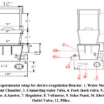 |
Figure 1: Experimental setup for electro-coagulation Reactor. 1. Water Storage tank, |
Analytical procedure
Arsenic concentration of water samples were carried out as per the procedure stated in standard methods for water and waste water analytical methods (APHA)49.The samples’ arsenic contents were assessed with an atomic absorption spectrophotometer (ELICO India, Model SL168) equipped with anhydride generator. Investigations of conductivity and pH have been made using calibrated cyber scan (pH6500) instrument. All chemicals used during analysis were of analytical or higher-grade reagent.
Results and discussion
Effect of current density
Figure-2 shows that for a 0.5 A (12V) current arsenic removal takes place with the passage of time for a pH range of 3.5 to 6.5.When the water pH is below about 8, ferric hydroxides are known to have a higher capacity for As (V) adsorption than As (III) adsorption. Based on this, As (III) might be oxidized to As (V), and arsenic might then exist as HAsO4. Since its molecular charge was negative, it electrostatically attracted positively charged metal hydroxides, removing arsenic from solution with high efficiency and ease. In studies, operating at current density of 0.54 A was favoured because it was more cost-effective 50. The quantity of arsenic reaches its lowest point after 1.5 hours. as seen in figure-2.The arsenic removal from batch of 500ppb and pH range from 3.5 to 6.5 shows that the concentration of arsenic decreases as time elapses and almost same results obtained at about 90 minutes duration as shown in Figure-3.51
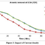 |
Figure 2: Impact of Current density Click here to View figure |
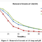 |
Figure 3: Removal of Arsenic at 1.0 Amp and pH Click here to View figure |
Effect of pH
Variation of pH with time at 1A current for varied pH levels, such as 3.5 and 6.5and 8.5 pH values shows that the pH reaches to the constant as current of 1A is made to flow for time span of 30 minutes duration figure-4. Because the major As (III) species H3AsO3 (pKa = 9.2) is uncharged at pH 1-7, which could have a detrimental effect on the efficacy of the arsenic removal process, the As (III) adsorption is better at a high pH. However, for As(V), its removal is generally more effective at a low pH since the adsorption effectiveness declines as the amount of H2AsO4 (pKa = 7) in the aqueous solution drops.52
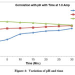 |
Figure 4: Variation of pH and time Click here to View figure |
For different concentration of Arsenic at 6.5pH
For 500 ppb, there is sudden decrease in concentration with respect to time
For 200 ppb the Arsenic concentration decreases with almost steady rate for about 50 mins, reaches to zero in an hour.
Since there is a significant decline in arsenic concentration with time for 100 ppb, it can be inferred that the higher the precipitate, the faster the decline in arsenic concentration at 6.5 pH, as shown in figure-5.
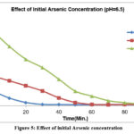 |
Figure 5: Effect of initial Arsenic concentration |
Effect of electrode spacing
Figure-6, illustrates how the amount of arsenic removed varies with changes in the inter electrode spacing. This result was achieved for an initial concentration of 500 ppb, and the treatment period for arsenic removal was set at 90 minutes.53-54 It also reveals that electrode spacing causes a drop in arsenic concentration. The pH values of the solution affect how effectively arsenic is removed. The efficiency curve for a fixed initial concentration of 100 ppb of arsenic reveals that as pH is increased, efficiency initially declines until it reaches a minimum at pH 6, and then gradually increases at about the same rate as it had decreased shown in figure-7.55–57 from pH 5 to 8, the ultimate elimination efficiency was unaffected, even if the elimination of arsenic is poorer at greater pH levels. Less levels of soluble arsenic could be attained once significant amounts of lepidocrocite were generated to act as arsenic adsorption sites. Furthermore, it was stated that pH had little effect on the final effectiveness of arsenic removal. 58
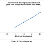 |
Figure 6: Electrode spacing Click here to View figure |
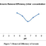 |
Figure 7: Removal Efficiency of Arsenic |
Conclusions
Arsenic can be removed from water using the developing technology of electrocoagulation since, it requires fewer chemicals, produces less sludge, doesn’t require mixing chemicals, and has lower operating costs than most of the existing technologies. The coagulation process can be used as an effective arsenic removal process for surface and groundwater another advantage of this process is that it frequently avoids the need for substantial influent and chemical input pre-treatment or conditioning. In the current study, the electrochemical oxidation method for removing arsenic from water employing iron as a sacrifice anode in an EC reactor was carefully examined. Additionally, pH, removal efficiency, and current density and their impacts were also studied during EC process. After arsenite was converted to arsenate, the arsenic was removed. Arsenate elimination by the Adsorption on metal hydroxides produced during the operation might be a part of EC. The final sample’s concentration of arsenic is within the acceptable range of 50 ppb. This method, which uses different technologies for arsenic removal, can be a financially advantageous one because it requires little initial investment, minimal operating and maintenance expenses, and uses less energy.During the electro-dissolution of iron in the EC reactor, there was no oxygen evolution. It showed how easily the test rector could be used for EC in addition to easy scale-up.
Acknowledgement
The Uttar Pradesh Council of Science and Technology (UPCST) has provided the authors with afinancial support under the be scheme/ project no. CST/D-2817,we would also very grateful to the Director, PSIT, Kanpur for his motivational support and approbation for the research work.
Conflict of Interest
There is no potential conflict of interest, according to the authors.
References
- Kumar, P.; Chaudhari, S.; Khilar, K.; Chemosphere, S. M.-; 2004, .Elsevier
- N Balasubramanian – Chemical Engineering &; 2001, .Wiley Online Library
- Singh, T.; Groundwater, K. P.-N. A. in; 2005, .taylorfrancis.com
- Roy, P. K.; Majumder, A.; Banerjee, G.; Roy, M. B.; Pal, S.; Mazumdar, A. Clean Technol Environ Policy2015, 17, 1065–1076. doi:10.1007/S10098-014-0862-0
- Rebhun, M.; Technology, M. L.-W. S. and; 1993, .search.proquest.com
- Osipenko, V. D.; Pogorelyi, P. I. Metallurgist1977, 21, 628–630. doi:10.1007/BF01083218
- Rajkumar, D.; materials, K. P.-J. of hazardous; 2004, .Elsevier
- Picard, T.; Cathalifaud-Feuillade, G.; … M. M.-J. of; 2000, .pubs.rsc.org
- Ögütveren, U. B.; Gönen, N.; Koparal, S. Journal of Environmental Science and Health. Part A: Environmental Science and Engineering and Toxicology1992, 27, 1237–1247. doi:10.1080/10934529209375794
- Kanematsu, M.; Young, T.; Fukushi, K.; Acta, P. G.-… et C.; 2013, .Elsevier
- Tewari, A.; Sharma, D.; Chemistry, A. D.-R. J. of; 2017, .rasayanjournal.co.in
- Moed, D.; Halem, D. van; … J. V.-W. S. and; 2012, .iwaponline.com
- Kameda, T.; Suzuki, Y.; Engineering, T. Y. E. C.; 2014, .Elsevier
- Hou, J.; Luo, J.; Song, S.; Li, Y.; Journal, Q. L.-C. E.; 2017, .Elsevier
- Hu, C.; Lo, S.; Technology, W. K.-S. and P.; 2014, .Elsevier
- Kong, Y.; Kang, J.; Shen, J.; Chen, Z.; Fan, L. Environmental Science and Pollution Research2017, 24, 2381–2393. doi:10.1007/S11356-016-7994-1
- Mak, M.; Rao, P.; research, I. L.-W.; 2009, .Elsevier
- Wang, L.; science, D. G.-J. of colloid and interface; 2015, .Elsevier
- Ridder, D. de; Wetering, T. van de; … T. V. D.-J. of W.; 2018, .Elsevier
- Mondal, P.; Tran, A.; Desalination, B. V. der B.-; 2014, .Elsevier
- Islam, S. M. D. U. Sustain Water ResourManag2019, 5, 359–380. doi:10.1007/S40899-017-0152-1
- Marathe, K.; Ortiz Uribe, I.; U M A R Yadav, K. K.; Gupt, N.; Khan, shakeel; Jadhav, S. v; Bringas, E.; Yadav, G. D.; Rathod, V. K.; Ortiz, I.; Marathe, K. v. Elsevier2015. doi:10.1016/j.jenvman.2015.07.020
- Pallier, V.; Feuillade-Cathalifaud, G.; Chemosphere, B. S.-; 2011, .Elsevier
- You, H.; engineering, I. H.-J. of environmental chemical; 2016, .Elsevier
- Shafaei, A.; Rezayee, M.; Arami, M.; Desalination, M. N.-; 2010, .Elsevier
- Pretorius, G.; WA, ; Johannes, ; Sa, W. & L.-W.; 1991, . journals.co.za
- Novikova, S. P.; T. L. Shkorbatova; E. Ya Sokol. Soviet Journal of Water Chemistry and Technology1982, 4, 353–357
- Goren, A.; Kobya, M.; Chemosphere, M. O.-; 2020, .Elsevier
- Guo, Z.; Zhang, G.; Fang, J.; Production, X. D.-J. of C.; 2006, .Elsevier
- Chen, X.; Chen, G.; technology, P. Y.-S. and purification; 2000, .Elsevier
- De, R. , W.; T.S.C.M.; Dijk, D.; Halem, D. Elsevier
- Mollah, M.; Schennach, R.; … J. P.-J. of hazardous; 2001, .Elsevier
- Mousazadeh, M.; Alizadeh, S.; Frontistis, Z.; Water, I. K.-; 2021, .mdpi.com
- Lu, J.; Zhang, P.; Management, J. L.-J. of E.; 2021, .Elsevier
- Silva, J.; Graça, N.; … A. R.-S. and P.; 2018, .Elsevier
- Sandoval, M.; Fuentes, R.; Nava, J.; … O. C.-S. and; 2019, .Elsevier
- Sandoval, M.; Fuentes, R.; Thiam, A.; Total, R. S.-S. of T.; 2021, .Elsevier
- Davis, C. C.; Knocke, W. R.; Edwards, M. Environ Sci Technol2001, 35, 3158–3162. doi:10.1021/ES0018421
- Moussa, D.; El-Naas, M.; … M. N.-J. of environmental; 2017, .Elsevier
- Dixit, S.; Hering, J. G. Environ Sci Technol2003, 37, 4182–4189. doi:10.1021/ES030309T
- Holm, T. R. J Am Water Works Assoc2002, 94, 174–181. doi:10.1002/J.1551-8833.2002.TB09461.X
- Vasudevan, S.; Lakshmi, J.; Sozhan, G. Clean (Weinh)2009, 37, 372–378. doi:10.1002/CLEN.200900031
- Lakshmanan, D.; Clifford, D. A.; Samanta, G. Environ Sci Technol2009, 43, 3853–3859. doi:10.1021/ES8036669
- Wilkie, J.; and, J. H.-C. and S. A. P.; 1996, .Elsevier
- Meng, X.; Bang, S.; Research, G. K.-W.; 2000, .Elsevier
- Zeng, H.; Arashiro, M.; research, D. G.-W.; 2008, .Elsevier
- Zhao, X.; Zhang, B.; Liu, H.; Qu, J. J Hazard Mater2010, 184, 472–476. doi:10.1016/J.JHAZMAT.2010.08.058
- Moreno C, H. A.; Cocke, D. L.; Gromes, J. A.; Morkovsky, P.; Parga, J. R.; Peterson, E.; Garcia, C. Ind Eng Chem Res2009, 48, 2275–2282. doi:10.1021/IE8013007
- Rice, E.; Baird, R.; Eaton, A.; Clesceri, L. Standard Methods for the Examination of Water and Wastewater; 2012
- Can, B. Z.; Boncukcuoglu, R.; Yilmaz, A. E.; Fil, B. A. J Environ Health Sci Eng2014, 12, 95
- Parga, J.; Cocke, D.; Valenzuela, J.; … J. G.-J. of hazardous; 2005, .Elsevier
- Yeo, K. F. H.; Li, C.; Zhang, H.; Chen, J.; Wang, W.; Dong, Y. Coatings2021, 11. doi:10.3390/COATINGS11111407
- Meng, X.; Korfiatis, G.; Bang, S.; letters, K. B.-T.; 2002, .Elsevier
- Chanpiwat, P.; Hanh, H.; Bang, S.; Journal, K. K.-H.; 2017, .Springer
- Zeng, H.; Fisher, B.; Giammar, D. E. Environ Sci Technol2008, 42, 147–152. doi:10.1021/ES071553D
- Jain, C.; research, I. A.-W.; 2000, .Elsevier
- Maurice, P. 2009
- Kumar, N. S.; Goel, S. J Hazard Mater2010, 173, 528–533. doi:10.1016/J.JHAZMAT.2009.08.117

This work is licensed under a Creative Commons Attribution 4.0 International License.


