Hydrocarbon Rich Liquid Fuel Produced by Co-pyrolysis of Sugarcane Bagasse and Rubber Seed Oil Using Aluminosilicates Derived from Rice Husk Silica and Aluminum Metal as Catalyst
Wasinton Simanjuntak1 , Simon Sembiring2, Kamisah D. Pandiangan1, Endah Pratiwi1 and Faradilla Syani1
1Department of Chemistry, The University of Lampung Jalan Prof. Soemantri Brojonegoro No. 1 Bandar Lampung, 35145 Indonesia.
2Department of Physic, The University of Lampung Jalan Prof. Soemantri Brojonegoro No. 1 Bandar Lampung, 35145 Indonesia.
Corresponding Author E-mail: wasinton.simanjuntak@fmipa.unila.ac.id
DOI : http://dx.doi.org/10.13005/ojc/330669
In this investigation, a mixture of sugarcane bagasse and rubber seed oil was subjected to pyrolysis for liquid fuel production, using aluminosilicates with different Si/Al ratios as catalysts prepared from rice husk silica and aluminum metal by electrochemical method. A series of pyrolysis experiments was conducted at the temperature range of 250 to 500oC, with the main purpose to investigate the effect of the Si/Al ratios of the catalysts on the chemical composition of liquid fuels produced. The liquid fuels produced were analyzed using gas chromatography-mass spectrometry (GC-MS) technique for component identification. The experimental results show that the most intense production of liquid took place at the temperature range of 350 to 480oC, while at lower temperatures gaseous product emerged as the main product. Analysis of the product using GC-MS technique revealed the presence of a series of compounds in the liquids, and broadly belongs to hydrocarbon, alcohol, ester, ketone, aldehyde, and acid. The results display significant effect of the catalyst composition on the composition of the liquids. The main trend observed is the tendency of increased the hydrocarbon content with decreased the Si/Al ratio of the catalyst, down to the ratio of 2.3 which produced liquid fuel with the highest hydrocarbon content (85%).
KEYWORDS:Liquid fuel; pyrolysis; sugarcane bagasse; rubber seed oil; aluminosilicate
Download this article as:| Copy the following to cite this article: Simanjuntak W, Sembiring S, Pandiangan K. D, Pratiwi E, Syani F. Hydrocarbon Rich Liquid Fuel Produced by Co-pyrolysis of Sugarcane Bagasse and Rubber Seed Oil Using Aluminosilicates Derived from Rice Husk Silica and Aluminum Metal as Catalyst. Orient J Chem 2017;33(6). |
| Copy the following to cite this URL: Simanjuntak W, Sembiring S, Pandiangan K. D, Pratiwi E, Syani F. Hydrocarbon Rich Liquid Fuel Produced by Co-pyrolysis of Sugarcane Bagasse and Rubber Seed Oil Using Aluminosilicates Derived from Rice Husk Silica and Aluminum Metal as Catalyst. Orient J Chem 2017;33(6). Available from: http://www.orientjchem.org/?p=40940 |
Introduction
In response to the present energy situation, in which the global demand for fuels continuous to increase, searching for alternative and renewable energy sources has been extensively carried out around the world. This initiative has been taken in acknowledging the insecurity of energy supply in the near future if the world continues to rely on fossil fuels. In this respect, fuels derived from biomass are, in principle, the most ideal solution for several reasons. The availability of various types of biomass in practically all regions around the globe, together with their renewability, support the sustainability of raw material for production of renewable energy sources (biofuels). As natural organic matter, biomass is environmentally friendly due to very low content of sulphur and nitrogen. For this reason, the amount of nitrogen oxides (NOx) and sulphur dioxide (SOx) gases produced from combustion of biofuels is much lower than those released from the utilization of fossil fuels. Furthermore, the CO2 gas released from combustion of biofuels are naturally consumed by plants through photosynthesis, making biofuels as CO2 neutral energy sources.
Among liquid biofuels, liquid fuel obtained by pyrolysis of biomass continues to gain growing interest. Although has not reached commercial level as the case with bioethanol and biodiesel, pyrolytic liquid fuel offers considerable advantage over the other two liquid fuels, primarily in term of raw material. It is well known that product of bioethanol as well as biodiesel relies on specific substrates, e.i. reducing sugar for production of bioethanol1,2,3, and vegetable oils4,5 or animal fats6,7 for production of biodiesel. Pyrolysis, on the other hand, is not limited by the raw material, in a sense that this technique could be applied to any type of biomass, thus offering unlimited opportunity for intensive development of the technique to enable the production of liquid fuels. In addition, the quality of liquid fuel to suite various needs can be improved using different upgrading processes8,9,10.
In recognizing the potential of pyrolytic liquid fuels, production of liquid fuel by pyrolysis of different biomass raw materials has been extensively investigated. Various biomass samples have been tested, among others are forest residue11, refinery residue12, lignin10, cassava13, wood and agricultural residues14, lignocellulosic15, micro algae16. In general, the results of previous investigations suggest that pyrolysis of solid raw materials tends to production of lesser amount of liquid fuel compared to that obtained from liquid raw materials. For this reason, in this current study sugarcane bagasse and rubber-seed oil was co-pyrolyzed in an attempt to optimize the production of liquid fuel from this abundantly available solid biomass.
In addition to raw materials, catalyst is another aspect of pyrolysis investigated progressively, since catalyst is acknowledged functions not only to enhance the pyrolysis process but also determines the types of chemical composition of liquid fuel produced. For these reasons, various catalyst systems have been studied such as zeolite and silica alumina8, noble metal, Pd/C16, USY zeolite17, natural and synthetic zeolite18, and aluminosilicate materials19-20. Aluminosilicate is of particular interest since this class of material can be produced with simple methods and from relatively cheap raw materials, and the composition, primarily Si/Al ratio, can be adjusted easily. This latest property of aluminosilicates silicate is very important since the performance of aluminosilicates is strongly influenced by their Si/Al ratio.
Considering their performance as catalyst and the effect of the Si/Al ratios, in this investigation a series of aluminosilicates with different Si/Al ratios was synthesized from rice husk silica and aluminum metal using electrochemical method, adopting the method applied in previous study21. This preparation method was selected considering the main feature of electrochemical process, in which the quantity of the electrolysis product depends on electrochemical variables, such as the potential and electrolysis time, applied. In this respect, the quantity of Al3+ ions resulted from electrochemical oxidation of aluminum metal used as anode is influenced by the potential and electrolysis time. Therefore, in principle, the aluminosilicates with different composition (Si/Al ratio) can be produced by varying the potentials and electrolysis times. Of aluminosilicates produced will vary, therefore will lead to production of aluminosilicates with varied Si/Al ratios. The aluminosilicates were then subjected to calcination treatment at 700°C for 6 hours, and then tested for pyrolysis experiments, with the main purpose to study the catalytic activity of the catalysts. The liquid fuels were characterized using GC-MS method13,16,17 method to compare the composition of liquid fuels produced using different catalysts, taking the emphasis on the hydrocarbon content of the fuels.
Experimental Method
Materials
The chemicals used in this study, sodium hydroxide, nitric acid, are reagent grade obtained from Aldrich. The aluminum metal rods ware purchased from CV Aluminium Jaya Perkasa, Jakarta. Rice husk was obtained from local rice milling industry in Bandar Lampung.
Instruments
The main equipments used in this study was GCMS-QP2010 SE SHIMADZU for identification of the chemical composition of the liquid fuels produced, and. The PANalytical Epsilon 3 XFR instrument was used for elemental analysis of the aluminosilicates.
Procedures
Extraction of rice husk silica
Rice husk silica was obtained using an alkali extraction method reported in literatures 22,23. Typically, a sample of 50 g dried husk was mixed with 500 ml of 1,5% NaOH solution in a beaker glass. The mixture was boiled for 30 min, and then allowed to cool to room temperature and left for 24 h. The mixture was filtered to separate the filtrate which contains silica (silica sol). To obtain solid silica, the sol was acidified by dropwise addition of 10% HNO3 solution until the sol was converted into gel. The gel was aged for three days, and then rinsed repeatedly with deionized water to remove the excess of acid. The gel was oven dried at 110oC for eight hours and ground into powder.
Preparation of aluminosilicate
Preparation of aluminosilicate was carried out using an electrochemical apparatus which consists of a home-made glass container with a cover having four drilled holes for assembling the electrodes. Four electrodes were used, two graphite rods as cathode and two aluminum rods as anode. The electrodes were fixed on the cover and inserted vertically into the cell at a distance of 2 cm from each other, with a 3 cm distance between the bottom of the electrodes and the bottom of the cell to allow easy stirring of the sample during the experiment. The cell was then connected to a variable voltage supply to allow the conduct of experiments at different potentials.
For preparation of aluminosilicate, 20 grams of dry silica was redissolved in 600 mL of 1.5 wt% NaOH solution in the solution was transferred into electrochemical chamber, and then diluted into 2.0 L using distilled water. To commence the experiment, the potential was adjusted to a specified value and electrolysis was carried out at specified time. In this study, experiments were carried out at 6, 8, 10, and 12 volt, and reaction time of 1, 2, and 3 hours for each of the potentials used, therefore, 12 aluminosilicates precursors were produced. The precursors were then dried and subsequently calcined at 700oC for six hours.
Pyrolysis experiment
A typical sample for pyrolysis experiment was prepared by mixing 200 mL of rubber seed oil and 50 gr of sugarcane bagasse. The mixture was allowed to stand at room temperature for 24 hours to allow the two raw materials to mix thoroughly. For pyrolysis experiment, 10 gr of catalyst was added into the raw material, and then the sample was transfer into pyrolysis unit. Pyrolysis process was carried out by setting the peak temperature of 500oC, and the liquid produced was collected. The liquid was transferred into separatory funnel for separation of organic phase (liquid fuel) and water phase. The liquid fuel obtained was then analyzed by GCMS, with the aid of MS Library system of Wiley 275 for tentative identification of the chemical composition of the liquid fuel.
Results and Discussion
Aluminosilicates preparation
Asa previously described, the preparation of aluminosilicates was conducted by applying different potentials and electrolysis times, with the aim to produce aluminosilicate with different Si/Al ratios. The experimental results are presented in Table 1.
Table 1: The composition (Si/Al) ratio of electrochemically prepared aluminosilicates using varied potentials and electrolysis times. The samples with * mark were selected for pyrolysis experiments.
| Potential (V) | Time (hour) | Si/Al Ratio |
| 6 | 123 | 9.6*3.32.3 |
| 8 | 123 | 5.1*4.63.9 |
| 10 | 123 | 7.2*3.3*1.5 |
| 12 | 123 | 5.12.3*1.0* |
As can be seen in the data (Table 1), for each potential used, increased electrolysis times led to decreased Si/Al ratios. This pattern indicate that extention of reaction times produced more Al3+ which is in accrodance with the nature of electrochemical process. The variations in Si/Al ratios due to different potentials was also observed, in which the general trend observed is decreased Si/Al ratios with increased potenstials used, which is also in accordance with the chracterstics of electrochemical process. However, the formation of several products with the same ratios should be acknowledged, which might be resulted from the experimental error. Out of the 12 samples, six samples (marked with *) were selected as representatives of composition for pyrolysis experiments.
The GC-MS analysis of liquid fuels.
A GC chromatogram of liquid fuel obtained using aluminosilicate with the Si/Al ratio of 9.6 is presented in Figure 1, and identified components in Table 2.
Table 2: Chemical components of liquid fuel obtained using aluminosilicate with Si/Al ratio of 9.6
| No | Relative Percentage (%) | Retention Time (Min) | Compound | Formula | Category |
| 1 | 3.728 | 1.24 | 1-Nonene | C9H18 | Hydrocarbon |
| 2 | 3.808 | 3.10 | 1-Heptanol | C10H22O | Alcohol |
| 3 | 6.167 | 0.58 | 1-Decene | C10 H20 | Hydrocarbon |
| 4 | 6.320 | 0.93 | Octadecane | C18H38 | Hydrocarbon |
| 5 | 9.192 | 0.91 | 1-Undecene | C11H22 | Hydrocarbon |
| 6 | 9.386 | 1.17 | 2-Butyl,1-Octanol | C12H26O | Alcohol |
| 7 | 9.667 | 0.58 | 4-Undecene | C11H22 | Hydrocarbon |
| 8 | 12.275 | 0.74 | 7-Tetradecene | C14H28 | Hydrocarbon |
| 9 | 12.457 | 2.74 | 2-Butyl,1-Octanol | C12H26O | Alcohol |
| 10 | 15.362 | 3.01 | 2-Butyl,1-Octanol | C12H26O | Alcohol |
| 11 | 17.909 | 1.54 | 3-Tetradecene | C14H28 | Hydrocarbon |
| 12 | 18.078 | 2.87 | Dodecane | C12H26 | Hydrocarbon |
| 13 | 20.319 | 0.56 | 7-Tetradecene | C14H28 | Hydrocarbon |
| 14 | 20.491 | 1.61 | 3-Tetradecene | C14H28 | Hydrocarbon |
| 15 | 20.656 | 6.38 | Tridecane | C13H28 | Hydrocarbon |
| 16 | 22.567 | 0.84 | 7-Hepatadecene | C17H34 | Hydrocarbon |
| 17 | 22.708 | 0.85 | 7-Tetradecene | C14H28 | Hydrocarbon |
| 18 | 22.915 | 1.61 | 8-Heptadecene | C17H34 | Hydrocarbon |
| 19 | 23.053 | 1.76 | Hexadecane | C16H34 | Hydrocarbon |
| 20 | 24.834 | 6.32 | 8-Heptadecene | C17H34 | Hydrocarbon |
| 21 | 24.989 | 6.02 | 8-Heptadecene | C17H34 | Hydrocarbon |
| 22 | 25.353 | 6.25 | 1-Heptadecene | C16H34 | Hydrocarbon |
| 23 | 29.862 | 5.96 | 2-Heptadecanone | C17H34O | Ketone |
| 24 | 30.314 | 7.22 | Methyl Palmitate | C17H34O2 | Ester |
| 25 | 31.716 | 2.49 | 3-Octadecanone | C18H36O | Ketone |
| 26 | 33.272 | 5.48 | 7-Decan-1-On | C10H18O | Ketone |
| 27 | 33.424 | 2.87 | 7-Decan-2-On | C10H18O | Ketone |
| 28 | 33.659 | 6.90 | Methyl Linoleate | C19H34O2 | Ester |
| 29 | 33.777 | 4.21 | 2-Heptadecanone | C17H34O | Ketone |
| 30 | 34.130 | 3.86 | Methyl Miristate | C15H30O2 | Ester |
| 31 | 35.036 | 8.61 | Oleate Acid | C18H34O2 | Acid |
| 32 | 36.320 | 0.80 | 9-Octadecanal | C18H34O | Aldehyde |
As typical of pyrolysis products of biomass sample it can be seen in Figure 1 that a large number of compounds were produced, and it should be acknowledged that not all of them were identified. In the case with the liquid fuel sample represented by Figure 1, as many as 32 compounds were tentaively identified. In order to simplify the results for more effective interpretation of the data, the identified pyrolysis products were classified into six categories based on the more common chemical types of the products. These six pyrolysis product categories are hydrocarbon, alcohol, ketone, acid,aldehyde, and ester.
Grouping the pyrolysis products into six common groups makes the comparison between the liquid fuels obtained using different catalysts, by defining the composition in term of the relative percentage of the groups. This grouping is also necessary since the variation in the chemical components is observed, making the comparison based on single compounds impractical. To estimate the proportions of each of the categories of the product type, the amount of each pyrolysis product assigned to each of the caategory, expressed as the peak area relative to the sum of the peak areas of all identified compounds, was calculated as a percentage. Then the values were grouped and summed to give relative percentage of each of the category and used for semi quantitative comparison between the liquid fuels obtained from different experiments. Using this approach, the composition of the liquid fuel obtained using aluminosilicaate with the Si/Al ratio of 9.6 is presented in Figure 2.
The liquid fuels obtained using the rest of the catalysts were treated similarly, and the results obtained with the use of all six catalysts are compiled in Figure 3. As can be seen in Figure 3, the main component of the liquid fuel is hydrocarbon which contributes 52% of the composition. The existence of hydrocarbons as the prime component is advantageous from the practical point of view since hydrocarbon is the most ideal fuel. Apart from this advantageous compositional characteristic, the presence of less desirable components, primarily acid should be taken into account, reflecting the need for upgrading process before the liquid fuel could be used in practical utilization.
The presence of different categories of compounds resulted from pyrolysis of different biomass has also been reported by others. As an example, the components of liquid fuel obtained by pyrolysis of wild reed 24 were grouped into seven categories: acids, oxygenates, phenolics, aliphatic hydrocarbons, monocyclic aromatics, polycyclic aromatics, and nitrogen-containing species. In the study it was also found that the oxygen-containing compounds are the dominant components of the liquid, which is quite different with the existence of hydrocarbon as the main constituent of the liquid fuel observed in this study. In another study25 the components of liquid fuel obtained by pyrolysis of Napier grass were divided into groups of hydrocarbon, aromatics, phenolics, alcohol, and other oxygenates. In the study it was also reported the existence of hydrocarbons as the main component, with the contribution of around 23 to 30%, depends on the catalysts used in the experiments.
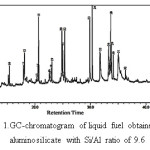 |
Figure 1: GC-chromatogram of liquid fuel obtained using aluminosilicate with Si/Al ratio of 9.6 Click here to View figure |
The experimental results in Table 1 display several interesting findings regarding the composition of the liquid fuels produced, which signify the important role of catalyst and the effect of calcination temperatures of the catalysts. As can be seen, in all experiments hydrocarbons emerge as the prominent constituent. For experiment without catalyst and that with the use of catalyst calcined at 600ºC, the relative percentages of hydrocarbon group are only slightly different. The relative percentages of hydrocarbon was found to increase significantly with the use of catalysts calcined at higher temperatures, and reached the highest value of 96% with the use of catalyst calcined at 800ºC, followed by slightly decrease to 93% with the use of catalyst calcined at 900ºC. Another important result showing the role of catalyst is the formation of acids, in which it was found that in the liquid fuel produced without catalyst contains the highest percentage of acid (10%) but decreased sharply with the use of catalyst. Acknowledging the highest hydrocarbon content and the absence of acid, it was then concluded that the liquid fuel produced with the use of catalyst calcined at 800ºC as the most potential liquid fuel for further study.
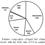 |
Figure 2.: Relative composition of liquid fuel obtained using aluminosilicate with the Si/Al ratio of 9.6 as catalyst. Click here to View figure |
Apart from the promising results obtained in this study, it should be acknowledged that the yields of the liquid fuel achieved by the processes are still relatively small (27.3-45.8%). Therefore, further investigation still needed, particularly to improve the yield of the process.
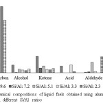 |
Figure 3: Chemical compositions of liquid fuels obtained using aluminosilicate catalysts with different Si/Al ratios Click here to View figure |
Conclusions
The results obtained clearly indicate that the composition of the catalyst imparts significant effect on the number of the chemical composition of the liquid fuel produced. The significant effect of the catalyst composition on the liquid yield and the relative composition of the liquid was observed, with the most evident effect is increased relative amount of hydrocarbon and reduction of the acid as the Si/Al ratio increased.
Acknowledgment
The authors gratefully acknowledge The Directorate of Higher Education, The Ministry of Research, Technology, and Higher Education, Republic of Indonesia, for financial support through research grant, Hibah Kompotensi 2017, contract number: 582/UN26.21/KU/2017.
Refrences
- Sebayang, A. H.; Masjuki, H. H.; Ong, H. C.; Dharma, S.; Silitonga, A. S.; Kusumo, F.; Milano, J. Industrial Crops and Products. 2017, 97, 146-155.
CrossRef - Wong, Y. C.; Fikri, A. M. Orient. J. Chem. 2014, 30(2), 637-642.
CrossRef - Matilla, H.; Kuuskeri, J.; Lundell, T. Bioresour. Technol. 2017, 225, 254-261.
CrossRef - Pandiangan, K. D.; Arief, S.; Jamarun, N,; Simanjuntak, W. J. Mat Environ Sci. 2017, 8, 1797-1802.
- Wong, Y. C.; Devi, S. Orient. J. Chem. 2014, 30(1), 521-528.
CrossRef - Sales, E. A.; Ghiraradi, M. L.; Jorquera, O. Energy Conversion and Management. 2017, 141, 216-223.
CrossRef - Kirukbakaran, M.; Selvan, V. A. M. Renew Sust Energ Rev. 2018, 82, 390-401.
CrossRef - Galadima, A.; Muraza, O. Renew Sust Energ Rev. 2018, 81, 1037-1048.
CrossRef - Bridgwater, A. V. Environ Progr Sustain Energy. 2012 ,31, 261-268.
CrossRef - Fan, L.; Zang, Y.; Liu, S.; Zhou, N.; Chen, P.; Cheng, Y.; Addy, M.; Lu, Q.; Omar, M.M.; Liu, Y.; Wang, Y.; Dai, L.; Anderson, E.; Peng, P.; Lei, H.; Ruan, R. Bioresour. Technol. 2017, 241, 1118-1126.
CrossRef - Carrasco, J. L.; Gunukula, S.; Boateng, A. A; Mullen, C. A.; DeSisto, W. J.; Wheeler, M.C. Fuel. 2017, 193, 477-484.
CrossRef - Prithiraj, S.; Kauchali, S. S. Afr. J. Chem. 2017, 24, 95-115.
- Pattiya, A. Bioresour. Technol. 2011, 102, 1959-1967.
CrossRef - Oasmaa, A.; Solantausta, Y.; Arpiainen, V.; Kuoppala, E; Sipilä, K. Energy Fuels. 2010, 24, 1380-1388.
CrossRef - Won, W.; Maravelias, C. T. Renewable Energy. 2017, 114 , 357-366.
CrossRef - Nam, H.; Kim, C.; Capareda, S. C.; Adhikari, S. Algal Research. 2017, 24, 188-198.
CrossRef - Boxiong, S.; Chunfei, W.; Cai, L.; Binbin, G.; Rui, W. J. Anal. Appl. Pyrolysis. 2007, 78, 234-249.
CrossRef - Miandad, R.; Barakatan, M. A.; Aburiazaiza, A. S.; Rehan, M.; Nizami, A. S. Process Saf Environ Prot. 2017, 102, 822-838.
CrossRef - Zabeti, M.; Baltrusaitis, J.; Seshan, K. Catal. Today. 2016, 269, 156-165.
CrossRef - Jiraroj, D.; Chaipurimat, A.; Kerdsa, N.; Hannongbua, S.; Tungasmita, D. N. J. Anal. Appl. Pyrolysis. 2016, 120, 529-539.
CrossRef - Simanjuntak, W.; Sembiring, S.; Manurung, P.; Situmeang, R. T. M.; Low, I. M. Ceramics International. 2013, 39, 9369-9375.
CrossRef - Simanjuntak, W.; Sembiring, S.; Pandiangan, K. D.; Syani, F.; Situmeang, R.T.M. Orient. J. Chem. 2016, 32(4) 2079-2085.
CrossRef - Pandiangan, K.D.; Jamarun, N.; Arief, S.; Simanjuntak, W.; Rilyanti, M. Orient J Chem. 2016, 32(4) 3021-3026.
- Yoo, M. L.; Park, Y. H.; Park, Y. K.; Park, S. H. Energies. 2016, 9, 201-209.
CrossRef - Mohammed, I. Y.; Kazi, F. K.; Yusup, S.; Alaba, P. A.; Sani, Y. M.; and Abakr, Y. A. Energies. 2016, 9, 246-263.
CrossRef

This work is licensed under a Creative Commons Attribution 4.0 International License.
![]()
A New Edition of Web of Science
Journal Impact Factor
2022: 0.5
Five Year: 0.8
Journal is Indexed in

Cabells Whitelist
![]()


