Synthesis and Characterization of Carbon foam from Gelatin (Cfg)
Maria Ulfa1, Lisna Putri Setiawan1 and Ariesta Setyaningrum2
1Department of Chemistry Education, Faculty of Teacher Training and Education Universitas Sebelas Maret Ir. Sutami Street 36A Surakarta, Center of Java Indonesia 57126.
2Department of Chemistry, Faculty of Natural Science and Mathematic Universitas Gadjah Mada Sekip Utara Street Yogyakarta, DIY, Indonesia 51555.
Corresponding Author E-mail: ulfa.maria2015@gmail.com
DOI : http://dx.doi.org/10.13005/ojc/330231
Article Received on : February 11, 2017
Article Accepted on : March 24, 2017
In this paper, a carbon foam of gelatin (CFG) with large pore size was synthesized for the first time using gelatin as a carbon precursor and sulfuric acid as the catalyst which is pyrolyzed at 900 C for 3 h under argon atmosphere flow. The structural and textural properties of the CFG samples were characterized by scanning electron microscopy (SEM), energy dispersive X-Ray (EDX), thermal gravimetry analysis (TGA), Fourier transforms infrared (FTIR) spectroscopy and nitrogen adsorption–desorption techniques. The surface area of CFG sample is about 62.5 m2/g and pore size with average size range at 20-30 nm and broken hole size up to 10 12µ"> m according to the N2 isotherm curve and SEM. The high pore size of CFG and dominated by carbon and oxygen with the unique structure composed of disordered arrays of carbon nanopipes in a macropore system. TGA curve showed degradation of gelatin due to water weight loss and decomposition reaction of gelatin. The TGA results indicated that there was big CFG degradation at 1000 ºC that showed the high thermal stability of CFG. The study on thermal behavior and character of CFG structural would create a new generation of the hard template.
KEYWORDS:Carbon foam; gelatin; SEM; FTIR; EDX
Download this article as:| Copy the following to cite this article: Ulfa M, Putri L, Setyaningrum S. A. Synthesis and Characterization of Carbon foam from Gelatin (Cfg). Orient J Chem 2017;33(2). |
| Copy the following to cite this URL: Ulfa M, Putri L, Setyaningrum S. A. Synthesis and Characterization of Carbon foam from Gelatin (Cfg). Orient J Chem 2017;33(2). Available from: http://www.orientjchem.org/?p=31565 |
Introduction
Carbon foam as new material that has good conductivity, high thermal and mechanical stability which is attracting much research attention1. The application of carbon foam in wide range field has been reported as the adsorbent, support of catalyst and energy storage material2 .Porous solid carbon foam is considered as the most promising alternative for many applications. Carbon foam materials with a micro-macroporous texture and chemical properties are known as excellent thermal and chemical stability.In addition, carbon foam can be applied as the new hard template and easily regenerated using low energy consumption.
The synthesis of carbon foams using foaming process followed by a carbonization step3. The other researcher using self-sintering process. However, the process for preparing these materials is costly and tedious, and hence unfavorable for large-scale production and application. In the previous research, carbon foam synthesized via carbonization of the carbon source such as pitch, resin and sucrose using templating agent4. The templating method to produce carbon foam through multi-step procedure is not favorable in economic. Precursor carbon as templating agent is the new way to synthesized carbon foam due to the simplicity approach.
Templating methods are the way to synthesized porous material using replication procedure to generate the system of pore5. The result of pore system related with the shape and size of the template. The template properties such as inert, exhibit a specific surface area, a large pore volume and possess a high mechanical stability required to obtain some pore system. The inorganic framework such as zeolites, mesoporous silica, and mesoporous carbon are the most common template due to the regular structure and large pore size6,7.However, the use of these material template is too expensive so the research in this field rarely done by the researcher.
Gelatin, the polypeptide that has lots of amino acid, is the new generation of templating agent due to hydrophilic and hydrophobic properties8. The micelle formation of gelatin structures stimulates pore directing step as the soft templating process. Gelatin also has the high content of carbon gelatin which is could be used as the new generation of precursor carbon9. The several previous kinds of research were used precursor carbon such as sucrose to synthesize carbon by hard silica mesoporous templating10. The previous study reported that this method needed high energy and had complicated step11–13. Gelatin could be precursor carbon and produce carbon foam as the new inorganic template. Based on our experience, gelatin has been rarely investigated not only as precursor carbon foam but also as templating agent.
Previous studies have already reported the preparation of carbon foam from sucrose, resin and pitch materials by physical or chemical activation1,2,4. However, the carbon foam from this precursor are complicated or needs the expensive templating agent. To sum up, there is a lack of information in the literature about carbon foam prepared from gelatin. This lack in the existing literature is a motivation for the present study. The primary objective of this study is to investigate physical and chemical properties of carbon foam from gelatin by several forms of analysis, including SEM-EDX, XRD, FTIR, TGA and N2-adsorption analyzer. The method of carbon foam preparation proposed in this study by Pechini method3. Carbon foam in this paper was prepared with some simple modification and well suited to mass production. Simultaneously, it is an effective and economically way to obtain the new inorganic template for porous material synthesis.
Experimental Section
Materials
All chemicals in analytical grade were provided from Sigma Aldrich used without any purification. Gelatin technical grade (medium molecular weight (200 kDa) was purchased from Gel-Pro Australian supplier.
Instrumentation
The investigation of carbon foam samples using Philips X’Pert-MPD diffractometer by radiation of Cu Kα (k = 1.5418 Å). The operation of Cu anode at 40 kV and 30 mA. The isotherms adsorption desorption nitrogen of carbon foam measured by AUTOSORB-1 instrument (Quantachrome Co.) at -196ºC. The surface area and pore size of carbon foam sample measured by Brunauer–Emmet–Teller (BET) and Brunauer–Joyner–Halenda (BJH) method. The images of carbon foam sample recorded by scanning electron microscope (SEM, Hitachi H800) combine with Electron Dispersive Spectrometer (EDX) to verify the presence of elemental inside the carbon foam samples. Fourier transform infrared spectroscopy (FTIR) was conducted on a Bruker Vertex 70 spectrometer over a range of 400–4000 cm−1 at a resolution of 4 cm−1.
Procedure
Preparation of Carbon foam from Gelatin (CFG)
Carbon foam from gelatin, designated as CFG, was prepared using gelatin as a structure-directing agent and carbon precursor. Gelatin CFG was syntesized by modified Pechini method3. At first, 0.01 mol sulfuric acid and 100 ml destillation water were mixed carefully. Then, 1.5 g gelatin was added to the prepared solution. After stirring for about 60 min, 1.0 g gelatin was added to the resulted mixture. The mixture solution was stirred 150 rpm and heated at around 90°C for 45 min. The resulted compound was heated at 150°C in oven for 15 h to inobt a foam like gel or resin. The provided material was calcined at about 900°C in condition of argon atmosphere for 3 h. The synthesized CFG was rinsed with deionized water, and finally dried in desiccator.
Result and Discussion
In Fig 1 shows the typical picture of a single broken carbon foam from gelatin (CFG) that clearly has a foam-like structure by the simple camera and SEM. These images indicate that the sulfuric acid treatment is a key factor in forming the foam-like structure on the CFG preparation.The resulting foams from CFG exhibited hard, smooth outer surface and aligned, disordered tubular internal pore structures. Representative 2D images of pore size and morphology obtained using SEM are shown in Fig. 1. The images show that the pore size an average of ~100 μm, are consistent regardless of sulfuric acid treatment. In addition, the pore morphology is a mixture of irregular pipe, disordered elliptical, and spherical shapes. The hard outer surfaces, which were characteristic sample, are also visible in SEM micrograph. The broken holes through the surface layer of the foams (diameter ~ 10 μm), generated by the vaporization of water during the foaming process.
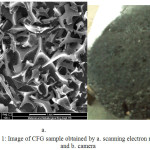 |
Figure 1: Image of CFG sample obtained by a. scanning electron microscope and b. camera
|
Gelatin structure as carbon precursor is very important to control characteristic of the carbon foam pore system. The Large pore of carbon foam obtained by reduction process of gelatin molecule which is hydrocarbons convert to elemental via losing of hydrogen, oxygen, and nitrogen atoms. The loss of this element from gelatin molecule describes the mass loss of gaseous species. The carbonization process cause mass loss of these gasses such as hydrogen, water, ammonia, however, are generated during carbonization process, so when the temperature is high and organic material is going to become hard and fragile, the presence of these species can create a diffuse microporosity. In the case of hydrogen, gaseous molecules are small and can diffuse quickly and without defect creation, but in the case of large molecules, such as water, diffusion is slower and microporosity more accentuated. This fact shows that CFG could be carbon matrix candidate which due not only to the molecular size but also in the matrix shape. The size and shape of porous carbon CFG predict appeared by the weight loss of water and ammonia as huge polar molecules in gelatin.
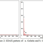 |
Figure 2: EDAX pattern of : a. Gelatin and b. CFG
|
Tabel 1: Chemical Composition of gelatin and CFG
|
Atomic (%) |
||
| Element | Gelatin | CFG |
| C | 54.9 | 79.9 |
| O | 28.8 | 18.9 |
| N | 15.5 | 0 |
| Na | 0.5 | 0.5 |
| Other | 0.3 | 0.7 |
Energy dispersive spectroscopy (EDS) measurements (Fig 2) show that the dominant elements of CFG are carbon and oxygen (the Au comes from fine Au grains coated for better electrical conductivity). In the major peak of C(79.9%) and O (18.9%) on carbon foam sample, indicating that the resulting carbon foam composed of carbon and oxygen phase as same as the previous research by Ge [8]. The mass loss of N from CFG shows decomposition process from gelatin during carbonization step. In addition, the peaks of Na were also detected in the EDX spectrum in the presence of gelatin might originate from the gelatine preparation. The result of the elemental analysis shows that nothing sulfuric residue on CFGsuggests the presence of interaction between gelatin and sulfuric acid only on the preparation step but nothing on carbonization. The morphology of CFG describes of large numbers of hydroxyl groups presenting in gelatin inevitably interact with the negative charge of sulfuric acid by hydrogen bonding. That is the gelatin molecules should dominantly locate at the interface between sulfuric acid and gelatin chain (shown in Fig. 1). Some gelatin molecules may interact with sulfuric acid then sulfuric acid penetrates through the side chain of amino acid on whole gelatin molecule.
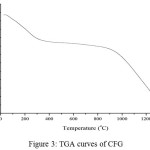 |
Figure 3: TGA curves of CFG |
The CFG were examined by differential scanning calorimetry (DSC) and thermal gravimetric analysis (TGA) in open pans under nitrogen. The DSC curve (Fig.3) presents a broad endothermic peak in the vicinity of 110°C on account of the continuous loss of moisture. The temperature (about 230°C), where the endothermic peak appears, is the melting temperature (Tm) of dried gelatin14. It was reported that the dried gelatin specimens undergo tertiary structure transformation and oxidation in air at the Tm. The splitting of peptide linkages of proteins starts at above 290 °C, and is indicated by several exothermic peaks15. Compared with the DSC curve, the TGA curve of CFG (Fig. 2b) shows a cumulative weight loss of about 20 wt% up to 200°C caused by the loss of moisture, and a weight loss of about 20 wt% from 200°C to 1300°C was associated with high thermal stability of material. The CFG sample also loses a significant amount of water over a slightly larger range, 25°C to 210°C. The CFG likely loss water over a larger temperature range due to the deformation of helical structure and other bonding between gelatin molecules and sulfuric acid that occur during ambient curing. This can also explain why, for a given temperature, the CFG sample lost twenty percent of water. The second event between 250°C and 425°C can be attributed to actual degradation of peptide bonds]. As shown in Fig. 3b, the gelatin foams undergo the same two distinctive changes in weight percent. As expected, however, the water lost between 25°C to 210°C is less for the foams 2–5%.
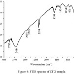 |
Figure 4: FTIR spectra of CFG sample. Click here to View figure |
The FTIR reflectance spectrum of the CFG is showed in Fig.4. The low-intensity bands appearing wave numbers at 698, and 935 cm-1 can be attributed to C–H vibrations. The carboxylic groups, CH2 and CH3 wave number observe at 1154 and 1454 cm-1. The bands at 1524, 1541 and 1590 cm-1 can be assigned to C=C and C=O vibrations in carbonyl groups respectively. The bands at 1154 and 1454 cm-1 appear due to vibrations of –CH2 or –CH3 groups. The characteristic bands due to C–O stretching vibrations are observed in the range of 100–1300 cm-1(10,16,17).The difficulties of assign the bands in the range of 100–1300 cm-1 due to the overlapping of functional groups. The bands at 1172 and 1268 cm-1 can be assigned to C–O–C stretching vibrations of alcoholic, phenolic and carboxylic groups. The band at 1103 cm-1 may be due to O–H. Finally, the IR spectrum confirms the presence of oxygen in the form of carboxylic groups at the carbon surface as expected due to the mass loss of water.
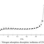 |
Figure 5: Nitrogen adsorption–desorption isotherms of CFG sample
|
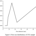 |
Figure 6: Pore size distributions of CFG sample
|
Nitrogen adsorption/desorption isotherms and their corresponding pore size distribution curves of the CFG materials are shown in Fig 5 and 6, respectively. The pore size distribution curves in Fig. 5 are calculated from the adsorption branches by using the BJH equation. The obtained isotherms of CFG sample can be classified as type-II according to the IUPAC with capillary condensation at relative pressures from 0.8 to 1.015,18. The combination of sharp and unsharp inflection of the CFG sample isotherm in P/P0 range from 0.5 to 0.8 is characteristic of capillary condensation within order and disorder pores.The isotherms are essential of type II with the surface area of CFG sample is 62.9 m2/g which concludes that CFG dominated by macroporous carbon. As shown in Fig. 5, the pore size distribution of CFG sample is the combination of mesoporous (20-50 nm) and macroporous range (up to 60 nm) which is obtained as good correlation data with SEM data.
The small hysteresis loop of CFG sample obtains at high pressure from SBA-15, indicating there is an increase of the pore size of this sample as expected before due to the loss of water and ammonia during high-temperature treatment as the previous research7 .This CFG sample shows a relatively multiform with maxima around 20-30 nm and up to 60 nm. The broken pipe sizes of pore systems (as observed from the SEM image) cannot be distinguished by the BJH analysis. The nitrogen adsorption isotherm for CFG sample exhibits relatively high adsorption at high pressures, indicating the presence of macropores. The CFG exhibits considerably low surface area due to its macropore system and more rigid void spaces, which makes it be the efficient matrix as the hard template in the nanomaterial synthesis.
Conclusion
Carbon foam CFG prepared by carbonization of gelatin as carbon precursor and sulfuric acid as catalyst. The pore of CFG materials generated by the release of water and ammonia molecule from gelatin. The pore type of CFG material was the macroporous system with average size is 20-30 nm and contain the huge size-disordered pipe up to 10 μm. The CFG material contains oxygen and carbon as the major element. The thermal stability of CFG was up to 1000ºC indicating that CFG could be the new hard template candidate in the future.
Acknowledgements
The author acknowledge financial support from the enviromental project 2014 from IDB (contract code Chem-IDB-Envi-112-0010-009-2016-Indobokor Group) in Indonesia.
References
- Rodríguez, E. & García, R.. Fuel Process. Technol. 2016, 1–11.
- Jana, P., Fierro, V. & Celzard, A.. Ind. Crops Prod. 2016, 89, 498–506.
- Jahanbakhshi, M.. Mater. Sci. Eng. C, 2017,70, 544–551.
- Tzvetkov, G., Tsyntsarski, B. & Balashev, K. Micron ,2016, 89, 34–42.
- Koo, J. B., Jiang, N. & Saravanamurugan, S. J. Catal. 2010, 276, 327–334.
- Ignat, M., Mertens, M., Popovici, E., Vansant, E. F. & Cool, P.2005, 7-12.
- Beretta, M. Doctoral thesis 40766, 2009, 221–214.
- Ulfa, M., Trisunaryanti, W., Falah, I. I. & Kartini, I. 10, J.Applied Chemistry,2014,4, 1–7.
- Ulfa, M., Trisunaryanti, W., Falah, I. I. & Kartini, I. Indones. J. Chem 2016, 16, 239–242.
- Darmstadt, H., Roy, C., Kaliaguine, S., Choi, S. . & Ryoo, R, Carbon N. Y. 2002, 40, 2673–2683.
- Farzin Nejad, N., Shams, E., Amini, M. K. & Bennett, J. C. Microporous Mesoporous Mater, 2013, 11, 239-246.
- Lee, J., Joo, S. H. & Ryoo, R. Microporous Mesoporous Mater, 2007,25, 33–36.
- Solovyov, L. A., Shmakov, A. N., Zaikovskii, V. I., Joo, S. H. & Ryoo, R. 2002, 40, 2477–2481.
- Van Den Bosch, E. & Gielens, C. Int. J. Biol. Macromol. 2003, 17, 46-55 doi:10.1016/S0141-8130(03)00046-1.
CrossRef - Ulfa, M., Trisunaryanti, W., Falah, I. I. & Kartini, I. J. Chem. Eng. Chem. Res, 2014, 1, 1–5.
- Koh, G., Zhang, Y.-W. & Pan, H. Int. J. Hydrogen Energy, 2012, 37, 4170–4178.
- Xianglan, Z., Shengfu, D., Qiong, L., Yan, Z. & Lei, C. Min. Sci. Technol. 2011, 21, 181–184.
- Do, D. D., Nguyen, C. & Do, H. D. Colloids Surfaces A Physicochem. Eng. Asp. 2001, 187–188, 51–71.

This work is licensed under a Creative Commons Attribution 4.0 International License.
![]()
A New Edition of Web of Science
Journal Impact Factor
2022: 0.5
Five Year: 0.8
Journal is Indexed in

Cabells Whitelist
![]()


