Computational Modelling Research into the Efficiency of Recirculation Air Diffusers
Vyacheslav Erikovich Shkarpet1, Ivan Nikolaevich Tislenko1, Kristina Vladimirovna Kochariantc1, Dmitry Vladimirovich Kapko2 and Iurii Andreevich Tabunshchikov3
1LTD “Arktos”, Russia, 196240, Saint-Petersburg, 6 Predportoviy proezd, 4
2LTD “NPO THERMEC”, Russia, 127238, Moscow, Dmitrovskoe shosse, 46-2
3Moscow Architectural Institute (State Academy) Russia, 107031, Moscow, Rozhdestvenka street, 11/4-1 building 4
DOI : http://dx.doi.org/10.13005/ojc/31.Special-Issue1.21
Article Received on :
Article Accepted on :
Article Published : 07 Nov 2015
Energy saving has recently become one of the priority tasks for designers and engineers working to improve ventilation and air conditioning systems. Central recirculation is a traditional way of increasing energy efficiency of ventilation systems. Application of such systems reduces the consumption of heat energy for heat the outdoor air. At the same time, this technology increases both the consumption of electric power to move air, and the space required for the air ducts. Moreover, air flows carry hazardous emissions between the rooms serviced by the same air supply plant. The purpose of this research is to develop a local recirculation diffuser, which would make it possible to use a local recirculation system (Naumov et al., 2014) free of the above-mentioned flaws typical of central recirculation systems. This article offers a local recirculation diffuser (LRD) scheme, describes computation modelling that confirmed the performance capacity and efficiency of the local recirculation diffuser, analyses ways to optimise its scheme in order to reduce power consumption, and lays forth the aerodynamic characteristics of the proposed air diffuser.
KEYWORDS:Ventilation systems; recirculation; local recirculation diffusers; computation modelling; intake air; pressure drop; velocity coefficient; ceiling effect; ANSYS CFX
Download this article as:| Copy the following to cite this article: Shevko V. M, Serzhanov G. M, Karataeva G. E, Uteeva R. A, Tuleev M. A. Computational Modelling Research into the Efficiency of Recirculation Air Diffusers. Orient J Chem 2015;31(Special Issue1). |
| Copy the following to cite this URL: Shevko V. M, Serzhanov G. M, Karataeva G. E, Uteeva R. A, Tuleev M. A. Computational Modelling Research into the Efficiency of Recirculation Air Diffusers. Orient J Chem 2015;31(Special Issue1). Available from: http://www.orientjchem.org/?p=12338 |
Introduction
Designers and engineers developing or improving ventilation and air conditioning systems, and their elements, have made energy saving one of their priority tasks in the past years (Zheng et al., 2012; Persily et al., 2015; Naumov and Kapko, 2013; Rackes and Waring, 2014; Bulck et al., 2013; Naumov et al., 2013), while much attention is paid to improving indoor air quality (Dutton and Fisk, 2014; Han et al., 2014; Kim et al., 2015). In traditional ventilation and air conditioning systems, outdoor air is processed in the central air conditioning unit and then distributed to individual rooms in the amounts prescribed by health and safety regulations (in the Russian Federation for office premises without natural aeration: 60 m3/ hours per one person (Rulebook of the Russian Federation SP 60.13330.2012 “Heating, ventilation and conditioning”, 2012)). In the cold season, outdoor air is heated to the temperature, which satisfies the comfort requirements specified in regulatory documents (Rulebook of the Russian Federation GOST 30494-2011 Residential and public buildings. Microclimate parameters for indoor enclosures).
The amount of heating energy consumed by the ventilation system to heat outdoor air can be reduced if we heat it by adding recirculation air from the rooms with significant internal heat emissions (in this article, the outdoor air is the air supplied from outdoors, cleaned and heated to a subambient temperature (≥6°С) in the central air conditioning unit). At the same time, central recirculation systems have a number of flaws: e.g., supply ducts are used not only to supply the required amount of outdoor air (as it is the case with the through-flow ventilation systems) but they also supply recirculation air in much greater amounts; as a result, air ducts have to be much bigger in size, and much more electric power is used to move air in the system. In addition, harmful substances can be transported between rooms. Advantages of the central recirculation system can be used and flaws avoided if we use a ventilation system with local recirculation diffusers (LRD) (Naumov et al., 2014). In that event, outside air and recirculation air are mixed at the diffuse outflow.
This article discusses a local recirculation diffuser capable of adding recirculation air to the outdoor air at the diffuser outflow in the amounts required to ensure the optimum temperature of intake air supplied in the work area. When outdoor air mixes with recirculation air inside the diffuser, there is a risk of condensate formation on the diffuser’s parts. Furthermore, in this case the impact of recirculation air on aerodynamic resistance in the bypass duct has to be taken into account. In the air diffuser proposed by the authors, outdoor air mixes with recirculation air at the outflow of the diffuser; as a result, it has now such drawbacks. The air diffuser’s main advantage lies in its ability to supply outdoor air at a temperature ≥ 6 ˚C.
Computation modelling was performed to validate the technical solution and optimise the design of the air diffuser in question. Actual testing of such a system in various non-isothermal modes is quite complicated to perform, so preliminary values of aerodynamic characteristics for this air diffuser were also obtained by means of computational modelling.
General
The local recirculation diffuser (Figure 1) consists of a plenum chamber (“PC”), rectangular in section, 540 x 570 mm, 390 mm high, with a side-feed duct ø250 mm in diameter for recirculation air, and a face plate with eddying cells; in the centre of the front plate is a round-shaped diffuser supplying outdoor air from the ventilation unit. Air is supplied to the diffuser through a duct ø125 mm in diameter, which goes perpendicular to the face plate in the centre of the PC. A fan feeds recirculation air from the serviced room through the side-feed duct. For the mixing at the diffuser outflow to be effective, outdoor air must mix with recirculation air and spread parallel to the ceiling.
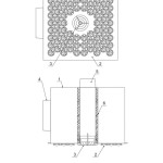 |
Figure 1: Recirculation air diffuser 1 – plenum chamber, 2 – face plate, 3 – diffuser, 4 – feed duct for recirculation air, 5 – feed duct for intake air, 6 – heat insulation. Click here to View figure |
The recirculation air diffuser is designed to supply 100÷180 m3 outdoor air per hour at a temperature of at least 6 °C. At this outdoor air temperature, the local recirculation diffuser is used to feed the maximum amount of recirculation air into the room (four amounts of outdoor air) – 720 m3/hour.
Eddying cells are directed radially outwards (Figure 2) to obtain a fan-shaped air jet spreading along the ceiling.
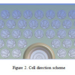 |
Figure 2: Cell direction scheme |
Computational modelling of the local recirculation diffuser’s capacity to diffuse air was performed on the ANSYS CFX platform. The system in the computational model (Figure 3) was assumed to have a heat-insulated ceiling with a 300×300 mm opening. The distance between the centre of the local recirculation diffuser and the exhaust outlet was 2 m. Open boundary conditions imitating unbounded space were assumed on the other boundaries. Since the problem has a symmetric nature, the model was created for a diffuser half with symmetric boundary conditions.
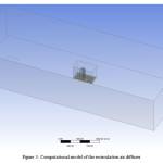 |
Figure 3: Computational model of the recirculation air diffuser Click here to View figure |
The computational model was based on the following input data:
- volumetric flow rate of intake air Li = 120 m3/hr;
- volumetric flow rate of recirculation air flow, Lr = 480 m3/hr;
- outdoor air temperature To = 6 °C;
- recirculation air temperature, Tr = 22 °C;
- temperature at the open borders of the room To = 22 °C.
In calculating the heat transfer, the authors used the features of a steel air diffuser panel, a plastic diffuser and, and 10 mm thick insulation on the outdoor air duct. The turbulence model k-ε was used in the calculations.
The purpose of the computation modelling in phase one was to make sure that the supply air jet spreads along the ceiling, outdoor air mixes efficiently with recirculation air at the diffuser outflow, and condensate formation on the surface of the steel air diffuser panel is improbable.
The computational modelling results (Figure 4, 5) demonstrate that at the diffuser outflow, outdoor and recirculation air flows mix efficiently and spread along the ceiling. At the same time, air temperature outside the air diffuser panel exceeds 16 °C, which rules out any probability of condensate formation. The temperature of the air diffuser panel (Figure 6) and on the outside of the air duct heat insulation ø125 mm also is higher than 16 °C.
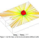 |
Figure 4: Air flow lines at the local recirculation diffuser outflow |
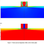 |
Figure 5: Velocity and air temperature fields on the vertical plane Click here to View figure |
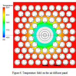 |
Figure 6: Temperature field on the air diffuser panel Click here to View figure |
The diffuser feeding outdoor air consists of the casing and the moving central unit. The central insert position was determined by the value of b – the clearance between the casing and the central insert. The above-mentioned results were obtained when b = 0 mm, and the central unit is tightly screwed and is flush with the casing. Diffuser usage experience (“Guidelines for Calculations and Application of Arktos Air Diffusers”, n.d.) demonstrates that advancing the diffuser’s central unit reduces pressure drops but the risk of losing the ceiling effect occurs. In the next phase of our research we identified the shape of the moved air, and the values of outdoor air pressure drop under various positions of the central insert.
On analysing the computational modelling results, one can infer that in case the central insert is advanced by b = 0÷24 mm, outdoor air spreads along the panel and then, upon mixing with the recirculation air, along the ceiling. Advancing the central insert reduces total pressure drops from 28 Pa at b = 0 mm down to 8 Pa at b = 24 mm.
Data on the supply jet of a standalone round diffuser (“Guidelines for Calculations and Application of Arktos Air Diffusers”, n.d.) contradict the independence between the outdoor air spreading along the ceiling and the central insert position. This inconsistence can be explained by the influence of recirculation air in the flow coming out of the deflecting eddying cells on the outdoor air flow. At certain temperatures of outdoor air we do not need to add recirculation air, so it was necessary to check how the outdoor air flow behaves when there is no recirculation. To this end, the authors did computation modelling without recirculation air. The outdoor air temperature was taken as To = 19 °C (no adding recirculation air is required at this temperature).
Upon analysing the computational modelling results of the local recirculation diffuser without recirculation it becomes clear that the outdoor air produces a ceiling effect when the central insert is advanced b = 0÷3 mm. With b > 3 mm, the outdoor air flow is directed along the diffuser axis (Figure 7).
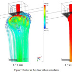 |
Figure 7: Outdoor air flow lines without recirculation Click here to View figure |
So, in the winter and transition periods, when recirculation air is used, the central insert may be advanced to reduce pressure drops, and in the summer period the central insert should be b ≤ 3 mm. In course of further improvements, a drive can be installed that would regulate the position of the central insert depending of the outdoor air temperature in order to receive an air stream spreading along the ceiling. Installing such a drive would reduce pressure drops in the cases recirculation air is added into the diffuser.
To estimate the local recirculation diffuser’s service area, the authors did modelling for two options with an extended domain of computation at b = 0 mm:
- recirculation air added, outdoor air temperature To = 6 °C;
- without recirculation, outdoor air temperature To = 19 °C.
Modelling results (Figure 8) demonstrate that in the case recirculation is performed, the gravitation force tears the air flow off from the ceiling at a distance of 4÷5 m from the air diffuser, and in the case without recirculation – at the 2 m distance.
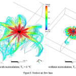 |
Figure 8: Outdoor air flow lines Click here to View figure |
Thus, the area serviced by one air diffuser is at least 4×4 m2.
To calculate the parameters of the intake air at the inflow into the serviced area, we need to know the velocity characteristics of the air flow formed by the diffuser. A good way to describe the velocity characteristics of the air flow is to apply a dimensionless adjustable velocity coefficient (Shepelyov, 1978; Grimitlin, 2004) defined as the product of relative air velocity and relative distance from the outlet point:
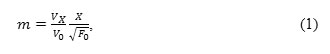
where VX is the maximum air velocity at the distance of X from the air diffuser;
Vo = L/Fo is the initial air velocity in the reference section F0;
L is the volumetric air flow rate,
In order to find the coefficient, gravitational forces were disabled in the computation model so as to obtain the largest possible area of the air flow spreading parallel to the ceiling. The modelling was carried out for b = 0 subject to recirculation. The maximum velocity Vx was determined at distances X = 1÷ 10 m with a 1 m increment in two directions, namely in the direction opposite to the recirculation air supply pipe, and perpendicular to the pipe. The PC cross-section Fo = 0.3 m2 was taken as reference section. Figure 9 shows the diagram of dependency between the velocity coefficient m and the relative distance x√Fo.
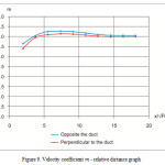 |
Figure 9: Velocity coefficient m – relative distance graph Click here to View figure |
It follows from the diagram on Figure 9 that the supply jet from the local recirculation diffuser behaves in accordance with standard laws of jet streams: the main stretch of the flow begins at a distance of more than five calibres (3 m), where the velocity coefficient practically does not change and takes the value m= 4.1 for both directions under review.
Thus, the velocity coefficient value m, which we found using computational modelling for the supply air jet shaped by the recirculation air diffuser under review, helps us find the velocity parameters of the air jet at any section of the work area using the methodology (Shepelyov, 1978; Grimitlin, 2004).
Conclusions
- The proposed local recirculation diffuser has all the advantages of the traditional recirculation ventilation system, while at the same time allows reducing power consumption on moving recirculation air, minimizing air duct dimensions and preventing transportation of contaminants between rooms.
- Computational modelling was used to substantiate a solution for the proposed local recirculation diffuser that would ensure efficient mixing of outdoor air with recirculation air. Mixing outdoor air with recirculation air outside the device helps avoid the problem of condensate formation on system parts, which permits feeding outdoor air at a low temperature (≥6 C) and preventing the impact of changes in recirculation air consumption on aerodynamic resistance of the bypass duct.
- Computational modelling was used to analyse the ways to cut the power consumption of the system. Advancing the central insert of the diffuser in the winter and transition periods will help to reduce pressure drops in the ventilation system. In course of further development the air diffuser can be equipped with a drive regulating the central insert position depending on the outdoor air temperature.
- Computational modelling was used to determine aerodynamic characteristics of the local recirculation diffuser. It was demonstrated that the supply air jet in the diffuser behaves according to standard laws of jet streams.
Acknowledgements
This research was supported by the Ministry of Education and Science of the Russian Federation under the federal target program “Research and Development on Priority Directions of the Research and Technological Complex of Russia in the Years 2014-2020” (Grant Agreement # 14.576.21.0037 dated 27 June 2014, Unique Identifier RFMEFI57614X0037).
References
- Shepelyov, A. I. (1978). Aerodynamics of Air Flows in a Closed Room (in Russian). Moscow, Stroyizdtat.
- Grimitlin, M. I. (2004). Air Distribution in a Closed Room (in Russian). St. Petersburg, AVOK-SEVERO-ZAPAD.
- Joo, J., Zheng, Q., Lee, G., Tai Kim J., Kim S. (2012). Optimum energy use to satisfy indoor air quality needs. Energy and Buildings, 46, 62-67. http://www.sciencedirect.com/science/article/pii/S0378778811005081.
- Naumov, A. L., Kapko, D. V. (2013). Results of experimental studies of a local air conditioning system in administration buildings. Industrial and Civil Engineering, 4, 17-19. http://www.pgs1923.ru/russian/rindex.htm.
- Naumov, A. L., Kapko, D. V., Efremov, V. V., Budza, A. O. (2013). Main directions to increase efficiency of ventilation and air conditioning. Industrial and Civil Engineering, 6, 56-59. http://www.pgs1923.ru/russian/rindex.htm.
- Van den Bulck N., Coomans, M., Wittemans, L., Hanssens, J., Steppe, K. (2013). Monitoring and energetic performance analysis of an innovative ventilation concept in a Belgian greenhouse. Energy and Buildings, 57, 51-57. http://www.sciencedirect.com/science/article/pii/S037877881200624X.
- Naumov, A. L., Kapko, D. V., Brodach, M. M. (2014). Ventilation system with local recirculation diffusers. Energy and Buildings, 85, 560-563. http://www.sciencedirect.com/science/article/pii/S0378778814007889.
- Rackes, A., Waring, M. S. (2014). Using multiobjective optimizations to discover dynamic building ventilation strategies that can improve indoor air quality and reduce energy use. Energy and Buildings, 75, 272-280. http://www.sciencedirect.com/science/article/pii/S0378778814001364.
- Persily, A. K., Ng, L. C., Emmerich, S. J. (2015). IAQ and energy impacts of ventilation strategies and building envelope air tightness in a big box retail building. Building and Environment, 92, 627–634. http://www.sciencedirect.com/science/article/pii/S0360132315300093.
- Guidelines for Calculations and Application of Arktos Air Diffusers (in Russian). Issue # 9.
- Rulebook of the Russian Federation SP 60.13330.2012 Heating, ventilation and conditioning.
- Rulebook of the Russian Federation GOST 30494-2011 Residential and public buildings. Microclimate parameters for indoor enclosures.
- Dutton, S. M., Fisk, W. J. (2014). Energy and indoor air quality implications of alternative minimum ventilation rates in California offices. Building and Environment, 82, 121-127. http://www.sciencedirect.com/science/article/pii/S0360132314002613.
- Han, Kw., Zhang, J. S., Guo, B. (2014). A novel approach of integrating ventilation and air cleaning for sustainable and healthy office environments. Energy and Buildings, 76, 32-42. http://www.sciencedirect.com/science/article/pii/S0378778814001698.
- Kim M. J., Braatz, Richard D., Kim J. T., Yoo Ch. K.. (2015). Indoor air quality control for improving passenger health in subway platforms using an outdoor air quality dependent ventilation system. Building and Environment, 92, 407-417. http://www.sciencedirect.com/science/article/pii/S036013231500222X.

This work is licensed under a Creative Commons Attribution 4.0 International License.
![]()
A New Edition of Web of Science
Journal Impact Factor
2022: 0.5
Five Year: 0.8
Journal is Indexed in

Cabells Whitelist
![]()


