A Review on Metal- Organic Frameworks (MOFS), Synthesis, Activation, Characterisation and Application
Okpara Sergeant Bull1* , Ibiso Bull2, Gloria Kelechi Amadi1, Chikwem Obaalologhi Odu1, Eyu Okpa1
1Department of Chemistry, Rivers State University, Nkpolu-Oroworukwo, Port Harcourt, Nigeria.
2Department of Medical Laboratory Science, Rivers State University, Nkpolu-Oroworukwo, Port Harcourt, Nigeria.
Corresponding Author E-mail: bullistics4real@yahoo.com
DOI : http://dx.doi.org/10.13005/ojc/380301
Download this article as:
![]()
A myriad of MOFs reported in the literature are made up of transition metal ions (nodes), single or in clusters, braced by organic supports or ligands. But there are other MOFs in which the central metal are non-transition elements. MOFs are prepared by the combination of inorganic and organic building units to give materials with high porosity, and other unique properties. Due to MOFs unique structural topographies, they find applications in diverse areas such as gas adsorption, gas purification and separation, catalysis, and in drug delivery. In this review article, the design and methods for MOFs synthesis, MOFs- activation, characterization, as well as organic linkers used for the making of MOFs are discussed. Furthermore the shortage of MOFs research based on silicon-containing aryl building units as well as boron-containing building units in comparison to carbon-containing building units are highlighted. We hope that this review will help researchers, industrialists and academics.
KEYWORDS:Activation; Characterisation; Metal-Organic Frameworks; MOFs, Synthesis; Organic Linkers
Introduction
Metal-Organic Frameworks (MOFs)1–3 are ordered structures consisting of inorganic and organic components. Unlike Covalent Organic Frameworks (COFs)4, most MOFs reported in the literature consist of transition metal ions (node), single or in clusters, interconnected by organic struts or ligands. A successful approach to obtaining a MOF depends on the choice of the building units which have significant influence on the topological structure and functionality of MOFs. Bridging ligands are important building units in the construction of MOFs. Hence, to control the structure of a MOF material, the selection of rigid, organic linkers is one of the most crucial decisions. For this reason, most of the organic linkers used in the construction of MOFs are usually molecules containing aromatic groups that give rigidity to the MOF network. The aromatic groups are in turn terminated or contain functional groups which are capable of coordinating with metal ions to give 1-, 2-, or 3-D networks as shown in Figure 1.
 |
Figure 1: Examples of metal ions and linkers used to give 1-,2- or 3D structures with porosity for gas adsorption. |
The functional groups in the aromatic organic ligand could be carboxylic acid,5–11 heterocyclic aromatic rings containing N atoms (pyridine)11–16 or other coordinating functional groups such as phosphonates17–21 and sulfonate.22,23 The nodes are usually made of one or more metal ions such as Zn2+, Fe3+, Mg2+ Ca2+, Zr4+, Ni2+, Co2+, Al3+ or Cu2+. A good number of MOFs display nanoscale porosity, high SBET and high thermal stability. One unique feature of MOFs over other solid porous adsorbents is that MOF materials can be tuned to carry out task specific jobs by varying of the pore size using judicious selection of the building blocks used in their synthesis.
Synthesis of Metal-Organic Frameworks (MOFs)
New MOF materials may be obtained when diverse influencing factors such as preservation of structural framework of the building units, optimal conditions of reaction, and metal ion type, as well as the type of organic ligand are considered. In a bid to prepare novel MOFs, significant attention has been devoted to the synthesis of new organic ligands for linkers and optimal conditions for the development of metal-organic ligand linkages. The structure of a MOF material as well as the geometry attained by a metal ion in a given MOF is greatly influenced by the characteristic features of the ligand such as its length, the number of connecting units on the ligand and their relative positions (linear, bent, trigonal or tetrahedral), bulkiness and any chirality present.24 As well as trial-and-error methods, many systematic studies involving hydro (solvo) thermal, microwave, sonochemical, electrochemical, mechanochemical, slow diffusion, solvent evaporation/ionothermal synthetic methods have all been reported.24–26
Hydro (solvo) themal methods
In general, the formation of a crystalline structural MOF material depends on factors such as solvent/solvent mixture, types of metal ion centres, ligand type as well as reaction temperature. Variations in solvent/solvent mixtures can result in the formation of different framework materials due to templating effects of the solvent molecule which have the capability of occupying the pores within the synthesised MOFs. Solvents usually used for the synthesis MOF materials include: DMF (dimethylformamide), DMA (dimethylacetamide), and DEF (diethylformamide). These solvent have relatively high boiling points and are also thermally stable. Hence, they are frequently used for the preparation of MOFs under extreme thermal conditions. Lower boiling point solvents such as water, methanol, and ethanol have also been used. However, if the heating of such solvents is anticipated to take place at temperatures above their boiling point, then the reactant solution is put in specially designed high pressure vessels such as a Parr autoclave. These solvents can also coordinate with metal centres and be incorporated in MOF structures.27 In solvothermal methods of MOFs synthesis the heterogeneous reaction takes place in sealed containers with autogenous pressure and temperature higher than the boiling point of the solvent.28,29 Thus, when making a choice for the reaction vessel (typically a screw-top vial), the scale of the reaction and the volume of solvent needed as well as the anticipated temperature range of the reaction are given consideration to ensure that sufficient headspace is left to give room for potential pressure build-up. In some situations, for example when the metal-ligand bond energies are relatively high, a modulator is used to hinder the rapid precipitation of amorphous material.30–34 Modulators are non-structural mono-topic linkers such as acetic acid, benzoic acid and hydrochloric acid which can form dynamic bonds with the metal precursor and assist in slowing down the formation of structural bonds by competing with the linkers for metal coordination sites. Modulators have been essential for the preparation of Zr-MOFs which contain strong Zr(IV)-O bonds. The concentration and chemical composition of a modulator influence defect corrections in the MOF structure as well as playing key a role on the MOF crystal size, habit and topology.35 Solvothermal MOFs synthesis is appealing for two reasons: (a) the problems of solubility of large organic molecules under these solvothermal experimental conditions are minimised and (b) the process of nucleation can be initiated more rapidly for the formation of complexes under the same conditions.36,37 The sealed reaction mixture is usually put in electrically heated ovens. The oven heating and cooling temperatures are controlled in order allow crystal growth defects to be resolved as the organic ligand continues to bind reversibly in a MOF thus promoting the growth and size of the crystals formed. The size of the crystals formed is very important for the purpose of characterization, as very small crystals may be unsuitable for single crystal X-ray crystallographic study. Although, this method enables the growth of bigger crystals the heating is usually done over hours or days, and thus is quite time consuming.
Microwave (MW) Assisted Methods
The application of electromagnetic radiation such as MW in synthetic organic and inorganic chemistry is well known.38–41 MOFs such as IRMOF-2, IRMOF-3, MOF-5 and HKUST-1 have been synthesised within seconds to minutes under microwave assisted conditions.42–44 The surface area of HKUST-1 obtained through this method was reported to be 1820 m2/g, which is higher than that reported for the same HKUST-1 obtained via solvothermal synthetic route (1550 m2/g).45 The MW method relies on the interaction of electromagnetic radiation with polar molecules in a solvent or conducting ions in a solid. In contrast to solvothermal methods, where thermal energy is transferred from the source of heat to the solution through the reaction container, in MW synthesis the interaction is directly with the reactants. The direct interaction of radiation with polar solvents develops hot spots which result in more efficient and faster heating. Furthermore, in MW assisted MOF synthesis crystallisation happens at the hot spots that form as a result of the direct heating of the solvent, as opposed to the wall of the reactor vessel associated with conventional heating methods. The precursors for the MOF synthesis are put in a microwave oven and heated, this results in rapid heating and short time for the formation of the MOF ranging between seconds to a few minutes. Consequently, MW assisted synthesis is much faster and results in a smaller particle size.25 Other than time saving benefits, microwave-assisted MOF synthesis also affords the synthesis of MOF crystals under variable reaction conditions.43,46 However, microwave–assisted MOF synthesis does not give good crystals large enough to obtain good structural data.40,42
Sonochemical Method
This method of MOF synthesis is facile, efficient and inexpensive. Ultrasound in the frequency range of 20 kHz–10 MHz,24,47 causes changes in pressure which generate cavities (small bubbles) in the solvent. Over time, these bubbles grow and collapse (cavitation). Thus, the formation and collapse of bubbles (cavitation) leads to local pressures and temperatures in excess of 1000 atm and 5000 K within the liquid. The hot spots which evolve lead to superior heating and cooling rates which accelerate the formation of MOFs. Examples of small crystalline MOFs that had been made by this method include Mg-MOF-74,48 MOF-177,49 MOF-550,51 and MIL-53(Fe).52 One advantage of this method over solvothermal synthesis is the avoidance of long reaction times as well as high heating temperatures.53 However, this method of MOFs synthesis usually produces materials with small crystal size that are unsuitable for single crystal crystallographic studies.
Electrochemical Method
Electrochemical synthesis is also an alternative way of synthesising MOF materials with precise process control.54 This method is fast and the purity of the products is high because of the absence of counter ions such as nitrates, perchlorate or chloride from metal salts.24 In this method ions are placed at the anode while the organic ligand is placed at the cathode and the electrochemical cell is filled with a conducting salt solution. Mueller and co-workers (BASF) pioneered the use of this method to synthesis Cu-MOF,54 which was made electrochemically by the use of a copper plate as the anode and 1,3,5-benzenetricarboxylic acid dissolved in methanol served as the cathode. The resulting electrochemical process gave a greenish blue precipitate of Cu-MOF (HKUST-1) within 150 minutes with a voltage and current of 12-19 V and 1.3 A respectively.54 BASF has also reported in the literature Al-fum MOF (Basolite A520) which can now be prepared in tonne-scale by the use of a water-based reaction system.55 This method has been used to make other MOFs such as [Cu2(BTC)3(H2O)3],56 and [Cu3(BTC)2].57In the literatureother researchers have applied electrochemistry in the preparation of different types of MOFs for varieties of applications.58–65 In addition, several review articles have described the successes and shortcomings associated with this synthesis method.25,26,66
Mechanochemical (Mechanosynthesis) Method
Contrary to the other methods so far discussed above that involve the use of solvents for the synthesis of MOFs, mechanochemical synthesis of MOFs is a solvent free method.24,67 The application of mechanical force on reactant species is capable of inducing both physical and chemical changes, which cause mechanochemical or solvent free synthesis of MOFs. Although this technique is well known in metallurgy and mineral processing it has only recently expanded rapidly into diverse areas of chemistry such as inorganic chemistry and pharmaceutical synthesis.68,69 In this method, chemical reactions occur by milling or grinding solids without any or with very little solvent.25,70,71 Thus with this method, the conventional solvothermal MOF reactors are substituted with mortar and pestle or a mechanical process by automated ball mills.72 In addition to no solvent wastes, this method MOF allows precursors with low solubility such as oxides, hydroxides and carbonates of metals to be used.25 Although, the method is a ‘solvent-free’ process, the purification stage may, however still require solvent. The major limitation associated with mechano-synthesis is scaling-up of the reaction, since the process is fundamentally a batch handling technique with a comparatively low rate of production.67 Nevertheless, from a green chemistry view point, this approach is an environmentally friendly means of preparation MOFs with a significant reduction in the cost of production.73,74 Mechanosynthesis has three different approaches for the synthesis of MOFs. These approaches are: (1) Solvent-Free Grinding (SFG), that avoid completely the use of solvent;75–79 (2) Liquid-Assisted Grinding, which is more versatile and faster as it uses small amount of liquid phases that enhance the mobility of the reagent,80–85 and (3) Ion-and-Liquid Assisted Grinding (ILAG),86 that makes use of a small liquid containing a small amount of salt additives to enhance the formation of MOF.72,87 One disadvantage of this method is that, crystals obtained through this means are unsuitable for single crystal X-ray diffraction studies.
Slow Diffusion Method
The mixing of solutions of metal salts and organic ligands without heating does not usually give MOF materials. However, there are some specific cases where the mixing of metal ions and ligand solution result in the formation of microcrystalline powder, which is not good for single crystal X-ray diffraction study. In a bid to solve the problem of formation of polycrystalline powder materials, slow diffusion of solvents is applied.88–90 The slow, gentle and steady diffusion of two solutions (of metal ion and of organic linker) in appropriate solvents generates larger and better quality crystals that tend to be suitable for single crystal X-ray diffraction analysis. In a typical slow diffusion method, the formation of the crystals occur in three different discrete layers of the layered solvents. For instance, Bunz and co-workers91 used this method to prepare a series of interpenetrated MOFs with anisotopic pore structures from a tetrahedral pyridine ligand. The bottom solvent layer contained the organic layer, while the upper solvent layer contained the metal ions. The middle solvent layer separated the organic linker solution from the metal ion solution for the slow diffusion to occur. In course of the slow movement of solvents from one layer into other layers, the actual growth of the crystals occurs at the boundary of the layers.
Solvent evaporation and ionothermal Method
In this synthetic method, crystals are formed by slow increase in concentration of mother liquor. The reactants are mixed in a suitable solvent and stirred continuously until the formation of a clear solution. The clear solution is thereafter transferred into a beaker and sealed. The formation of MOF crystals is usually initiated by either saturating the solution, or by the cooling of the solution, or by the removal of excess solvent. For example, Zheng et al. used this method to synthesise a variety of copper(II)-lanthanide(III) framework materials.92 In addition, Liao and co-workers used an ionic liquid as solvent for the synthesis and crystallization of a coordination polymer: [EMIM)[Cd(BTC)] [where (EMIM) is 1-ethyl-3-methylimidazolium, and (BTC) is 1,3,5-Benzenetricarboxylate] through the application of this method.93 This approach was also employed by other researchers to synthesise 3-D MOFs.94 In addition to these method discussed so far above, other approaches found in the literature25 include, template, atomic layer deposition, spray dryer, sol gel, supercritical35 and flow chemistry95 as shown in Figure 2.,25 timeline for the most common approaches used for the production of MOFs.
 |
Figure 2: Timeline of the most common synthetic methods used for the synthesis of MOFs.25 |
Activation of Metal-Organic Frameworks (MOFs)
MOFs maybe categorized either as rigid or flexible. Rigid MOF materials possess a comparatively stable and robust porous framework with permanent porosity comparable to that of zeolites. Flexible MOFs are framework materials that respond to factors such as temperature and pressure as well as guest molecules.96,97 The sensitivity of some MOFs toward temperature or pressure makes them outstanding for temperature/pressure molecular sieving which other traditional adsorbent like zeolites and activated carbons lack. Thus the intense current research efforts towards the industrial application of MOFs in gas separation and storage as well as catalysis can be attributed to their robustness, unique structural properties such as high thermal and chemical stability, unprecedented internal surface areas of up to 5000 m2/g and above, high void volumes of 55-90%, as well as low density from 0.21-1.00 g/cm3, which can be sustained upon the removal of guest molecules such as H2O from the pores.
When MOFs are being synthesised, solvent molecules or modulators used during the synthesis or sometimes excess organic linkers for example in the case of the synthesis of Cr-MIL-10198 may be unavoidably trapped in the pores or coordinate to the framework material.99 In order to access the permanent porosity and high surface areas of many framework structures, the trapped solvent molecules or the excess linkers in the pores of the framework materials must be removed. The process by which these trapped solvents are evacuated from the pores of the framework materials is termed activation. If the aim of an activation process is to obtain a MOF material with the highest possible surface area and porosity, then care must be taken during the activation of the MOF.100 Approaches used for the careful activation of MOFs include: conventional heating and vacuum; solvent-exchange; use of supercritical CO2 (scCO2); freeze-drying; and chemical treatments.
Conventional Activation
Conventional activation involves the removal of solvent and other guest molecules in the pores of MOFs by the application of heat and vacuum. This means of activation of MOFs is similar to the strategies used for the activation of zeolites and carbons. For example MOFs Cr-MIL-101 ([Cr3F(H2O)2(bdc)3]98 and UiO-66 [Zr6(O)4(OH)(bdc)12]101 have been activated successfully via this approach, (bdc = benzene dicarboxylate). The surface areas of Cr-MIL-101 and UiO-66 are 4100 m2/g and 1070 m2/g respectively. Both MIL-101 and UiO-66 have remarkable thermal and chemical stability that permits the application of conventional activation to them. But the application of this activation strategy for the purpose of accessing the complete porosity of many other MOFs is limited as a result of complete loss of crystallinity or lack of porosity at the end of the activation exercise.88,100,102 The loss of crystallinity and porosity maybe attributed to the fact that the solvent within the MOF pore changes from a liquid phase to a gaseous phase boundary, substantial surface tension and capillary forces are generated that cannot be counterbalanced by the moderate coordination bond energies in many MOF. As a result of this, other ways of MOFs activation are required in order to fully access the large internal surface areas of a large number of MOF materials.
Activation by Solvent-Exchange
Solvent-exchange entails the swapping of a high-boiling solvent such as DMF with a lower boiling point solvent such as trichlomethane followed by a milder activation under vacuum. Lower boiling point solvents are known to have weaker intermolecular interactions which results in the minimization of surface tension and capillary forces in the course of activation. Yaghi and co-workers were the first to use this strategy for the activation of MOFs.5,103 The iconic framework material, MOF-5(IRMOF-1),[Zn4O(BDC)3] was prepared in DMF-chlorobenzene. The structure could be retained and subsequently activated after switching the DMF-chlorobenzene for CHCl3. The result of the solvent exchange gave a microporous material with a Langmuir surface area of 2900 m2/g.5,104 Hupps and co-worker carried out further studies on IRMOFs by using conventional activation and solvent-exchanged activation.105 The IRMOF-3 activated conventionally displayed a surface area of 10 m2/g while the same study on IRMOF-16 showed no N2 uptake. However, when DMF was exchanged for CHCl3 or THF, the surface areas of IRMOF-3 and IRMOF-16 increased to 1800 m2/g and 470 m2/g respectively,105 although, higher surface areas were expected for IRMOF-3 and IRMOF-16 based on computational calculations.106 Thus, even though solvent exchange activation improves porosity, in some cases it still leads to materials with porosity less than expected from computational and single-crystal structure estimation.105 Solvent exchange with acetone coupled with heating cycles under vacuum was used to activate and increase the porosity of a series of isostructural MOFs NOTT-100, NOTT-101, NOTT-102, NOTT-103, NOTT-104, NOTT-105, NOTT-106, NOTT-107, NOTT-108 and NOTT-109 (NOTT = University of Nottingham).107 The SBET of 8 of these MOFs (except those of NOTT-104 and NOTT-108) after activation were reported to be: 1640, 2316, 2942, 2929, 2387, 1855, 1822 and 1718 m2/g, respectively.107
The Use of scCO2
The use of supercritical carbon dioxide (scCO2) for the activation of MOFs is an extension of solvent-exchange; in that scCO2 is used for the activation instead of solvent-switch such as CHCl3 or THF for DMF.35 The use of scCO2 is a milder activation approach compared to both conventional activation and solvent exchange activation, both of which may cause framework collapse.104,105 This is true in that the use of scCO2 foractivation of MOFs circumvents the liquid-to-gaseous phase change of guest solvent molecules and instead goes through a supercritical phase directly which bypasses the negative effect of surface tension and capillary forces associated with liquid-to-gaseous phase.104 The surface tension of liquid CO2, ethanol (EtOH), methanol (MeOH), acetone, dichloromethane (DCM), N,N-dimethylformamide (DMF), dimethyl sulfoxide (DMSO) and water are 0.6, 22.0, 22.1, 23.0, 27.8, 34.4, 42.9 and 72.7 dynes/cm respectively.108 Although Nelson et al. were unable to obtain SBET for IRMOF-16 using conventional methods, when these MOFs which contained Zn4O nodes and carboxylic acid organic linkers were activated with scCO2, IRMOF-3 displayed an SBET of 2850 m2/g which represent a 258-fold increase over conventional activation and 1.6-fold increase over solvent-exchange. The SBET observed for IRMOF-16 was reported as 1910 m2/g which represent a 4-fold increase over the same material when activated by solvent exchange.109 Although, the use of scCO2 for activation has been reported not to give the desired result in some cases,21,110,111 a good number of successes have been reported for the activation of MOFs.112–117 The driving force behind the intense interest in the use of scCO2 for activation of MOF materials maybe due to its low cost as well as the ease to scaling-up. Table 1. below depicts interesting results obtained via the use of scCO2 for activation. The MOFs are reported to display the largest SBET, pore volume, extreme pore and aperture sizes, encapsulated reactive species and dynamic structural features.
Table 1: Selected MOFs and some of their relevant material characteristics enabled by scCO2 activation.
|
MOF |
SBET (m2/g) |
Pore Volume (cm3/g) |
Ref. |
|
Nu-110 |
7140 |
4.40 |
113 |
|
MOF-210 |
6240 |
3.60 |
118 |
|
SNU-70ˈ |
5290 |
2.17 |
119 |
|
[Co6(btb)4(bp)3] |
5200 |
2.10 |
120 |
|
UMCM-9 |
4970 |
1.80 |
121 |
|
Bio-MOF-100 |
4300 |
4.30 |
122 |
|
FJI-1 |
4043 |
1.43 |
123 |
|
DUT-13 |
2532 |
1.98 |
124 |
|
IRMOF-74XI |
1760 |
3.41 |
125 |
|
P11-16/1 |
1009 |
N/A |
126 |
The concept of ‘‘flowing’’ scCO2 activation has also been applied in columns containing MOF samples.121 The scCO2 is made to pass through the MOF sample in the column and effectively displaces the guest solvent molecules. One benefit of this ‘‘applied scCO2 flowing technique’’ is that guest solvent molecules such as DMF in a MOF can be removed with ease without exchange of the DMF for CO2 in the pores.127 EtOH has been reported as a useful solvent used in the place of DMF because DMF damages some equipment components.104,105
Activation by Freeze-drying
Although this approach is relatively new,128 several research groups have applied it to the activation of MOF with various functionalities.104,129–133 The technique involves the exchange of the guest with another solvent following freezing-thaw cycles. For example, Lin and co-workers use this technique to activate two isoreticular Cu paddlewheel based MOFs ([Cu2(L)(H2O)2]) (L = methanetetra(p-benzoic acid).129 The guest solvent molecules were exchange for benzene and the sample left in benzene. Following this treatment, the sample was frozen at 0 °C, and then put under vacuum, and then warmed back to room temperature three times. At the end of the freeze-thaw cycles, the samples were put under vacuum at a temperature and pressure lower than the triple point of the solvent. Finally the sample was warmed under reduced pressure, wherein the benzene sublimed. The sublimation of the benzene by-passed the liquid phase and avoided the detrimental effects of surface tension and capillary forces.129 The resulting SBET values of the two isoreticular ([Cu2(L)(H2O)2]) MOFs after the freeze-drying activation were reported to increase significantly in comparison to the same MOF sample but subjected to solvent exchange activation. In addition, it was also reported that the X-ray diffraction pattern of the guest-solvent sample differed from the benzene-freeze-dried sample.
Benzene is known to be carcinogenic, as a result, Zhang and co-workers134 used cyclohexane (non-carcinogenic) in the place benzene for the activation of MOF [Zn2L(Im)]·7(DMF) (FIR-3; L = Tris((4-carboxyl)-phenylduryl)amine, Im = imidazole; FIR denotes Fujian Institute of Research). The conventionally activated material gave an SBET of 24 m2/g, while the cyclohexane-freeze-dried material exhibited an SBET of 497 m2/g
Li et al.135 reported the use of a gel-like freeze-drying strategy for the synthesis of hierarchically porous polyoxometalate-based MOFs (NENU-(HP-I), NENU-(HP-II), NENU-(HP-III), NENU-(HP-IV) and NENU-(HP-V) catalyst. It was reported that the freeze-drying process enabled the preparation of the material with high stability, large mesopore sizes as well as high pore volume.
Activation by chemical treatment
MOFs are also activated by treatment with chemicals (acid treatment). All the activation techniques discussed above are centred on guest solvent molecules that are neutral species. However, if the guest solvent molecules are ionic species or high boiling point solvents such as DMF, DEF or DMSO,136 then such molecules cannot be removed from a cavity or a coordination site of an evacuated MOF by mere heating since they have low volatility or, in the case of ions, they are not volatile.109,137–139 Hence, in cases where solvent molecules such as benzoic acid or other ionic species are coordinated in MOFs during synthesis (for example as modulators) then chemical treatment maybe the best option. For example, some Zr6-based node MOFs are known to possess excellent stability both in aqueous and acid solution.101 However, in most cases during synthesis a copious amount of acid (benzoic acid) is used to enhance and modulate the nucleation and growth into MOFs. At the end of the synthesis, the acid is removed via rigorous washing or by chemical treatment. It has been observed,138 that for a tetracarboxylate-porphyrin-based MOF such as PCN-222 (also referred to as MOF-545)137 that treatment with concentrated HCl followed by activation under vacuum and heat resulted in the formation of material with increased pore volume.138 However, the specific function of the concentrated HCl was not given. Similarly, tetracarboxylate-pyrene-and Zr6-containing MOF (NU-1000) studied by Hupp and co-workers revealed that HCl cleaved the coordinated benzoate from the Zr6 node. The resulting effect of the cleavage was a material with meso-porosity. Jeong and co-workers used chemical treatment dichloromethane for the activation of open metal sites in the copper- containing MOF materials (HKUST‑1 and Cu-MOF‑2).140 However, it was reported that strongly coordinated solvent molecules, such as DMF, were difficult to evacuate completely by the activation with DCM.136,140 Following this observation, Bae et al.136 applied this approach for the activation of open-metal sites in MOFs. They used a multiple coordination exchange (CE) process starting with acetonitrile (MeCN), MeOH, EtOH and finally with DCM to obtain complete activation of open coordination sites (OCSs). In addition, MOF-74 (Ni) was also activated with a multiple CE process.136
Characterisation of Metal-Organic Frameworks (MOFs)
The most important means for the characterisation of MOFs are: (1) single crystal X-ray diffraction (XRD) which provides absolute structural information about the MOF; (2) powder X-ray diffraction (PXRD) to establish crystallinity and phase purity of the bulk; (3) elemental analysis (4) thermogravimetric analysis (TGA) for the determination of the thermal behaviour of MOF and in some cases for the estimation of pore volume; (5) surface area measurement which provides information about the capability of a porous material for gas adsorption; (6) gas adsorption study which estimates the sum of the pore volume of MOFs; (7) infra-red spectroscopy which can be employed to determine the presence or absence of IR active functional group in the frame works; (8) scanning electron microscope (SEM) which measures the crystal size and morphology which can be coupled with energy dispersive X-ray spectroscopy (EDX); and (10) inductive coupled plasma optical emission spectroscopy (ICP-OES).
Single crystal X-ray Diffraction (XRD)
XRD is the best and most effective single method of characterisation of MOF materials to determine unambiguously its structure, i.e. information about the identity and arrangement of atoms in a single crystal. However, some major limitations are associated with XRD. For example, the collection of reliable data which is a function of the size (50 µm and above) and quality of the crystal. This can be challenging as the general procedures used to obtain large and high quality MOF crystals may not be adequate.35,141 In addition, MOF crystals usually have large amount of disordered solvents in their pores. SQUEEZE is the commonly used software for the processing of data due to disordered solvent in the pores of MOF structures.142 Although, the collection of data for MOFs is better at low temperature, the presence of disordered solvent means that the collection of data at higher temperature can sometimes yield better diffraction data as disordered solvent freely tumble (i.e. become highly disordered) and contributes less to the diffraction peaks.35,113 Furthermore, un-activated MOFs tend to diffract better than activated ones. Symmetry mismatches are another major challenge associated with MOF refinement. That is the symmetry mismatches between lattice of metal nodes (usually higher symmetry) and those of lattice of organic connectors (usually lower symmetry). Thus, MOF structures with higher symmetry linkers are less troublesome to refine than those with low symmetry organic connectors. In addition, interpenetration in MOF structures may also pose problems in the crystallographic characterisation of MOFs even though, interpenetrated MOF materials frequently display better diffraction patterns because they are more dense and possess less empty space.143–145
Powder X-ray Diffraction (PXRD)
PXRD is used for the characterisation of MOFs, principally if the crystals are too small for single-crystal X-ray diffraction. The powder X-ray diffraction patterns provide information about the crystallinity of MOFs (since sharp diffraction peaks are indicators of crystallinity of the bulk MOFs material) and can be used to obtain unit cell parameters and determination of the bulk crystallinity after de-solvation. Powder patterns can be predicted from the single crystal structure and compared with experimental powder patterns or through the use of computational modelling146–148 to verify product identity.
One common method for the preparation of sample for PXRD analysis involves the loading of finely ground powdered sample onto a flat plastic, glass or aluminium disc sample holder. The sample can either be dry-loaded onto the sample holder or attached using oil or volatile solvents. This method of sample preparation works well for most MOF samples but sometimes plate or needle morphology crystals tend to deposit with preferred orientation when MOF samples are prepare by this way. The calculation of simulated powder patterns is based on the assumption that crystallites are randomly oriented.35Based on this assumption, there may be significant differences in peak intensities between simulated and experimental PXRD patterns.
To circumvent problems linked with preferred orientation, MOF samples are usually rotated continually during data collection in a conventional sample holder or in a capillary tube. The spinning of the sample enables the orientation of the crystallites to align in a nearly random with respect to the detector. Overly broad diffraction peaks are features of undersized crystallites and associated Scherer broadening instead of poor crystallinity. It is difficult to solve a structure from powder data although it has been done in some cases.141,149,150
Elemental Analysis
Elemental analysis is also a very useful tool for the determination of the composition/purity of MOF frameworks. It measures the percentage of carbon, hydrogen and nitrogen in a sample which can then be compared with the molecular formula of the MOF provided by the single-crystal X-ray diffraction. Thus the experimentally determined elemental analysis result can be compared with expected result based on the molecular formula generated from the single-crystal X-ray diffraction. This comparison gives an indication of the purity of the MOF in terms of composition and the possible presence of additional solvent molecule(s).
Thermogravimetric Analysis (TGA)
TGA is used to determine the thermal stability as well as the decomposition characteristics of a given MOF by observing its weight loss as a function of temperature, usually from room temperature to several hundreds of degrees centigrade until the organic component is lost.8,103,151–153 The weight loss can be used to determine the amount of solvent in the pores and how the MOF decomposes at different temperatures. With this information the percentage weight loss of different components and stages can be calculated. Thus, in a typical TGA trace one will see several “segments” which correspond to the loss or decomposition of different components of the MOF framework. The mass that remains after the heating is usually the oxidized metal species such as the carbonate or the metal-oxide if air is used.103,151,152 Although the loss mass does not necessarily mean structural changes. Complementary measurements are worth taking to verify the thermal stability of a MOF with temperature variation including in situ PXRD35,154,155 and /or sorption measurement carried out on samples subjected to changing temperatures.156
Surface Area Measurements (N2 Adsorption & Desorption Isotherms)
Adsorption isotherms for inert gases at cryogenic temperatures can be used for the determination/estimation of apparent surface areas of MOFs. Surface area measurement is a vital means of estimating the gas storage capability of porous materials.157,158 For example MIL-101 and MOF-177 have SBET of 4100 m2/g and 4500 m2/g respectively based on N2 adsorption isotherm while zeolite Y and activated carbons have surface areas of 904 m2/g and 2000 m2/g respectively.159 Adsorption of gases by MOFs is primarily due to interactions of guest gas molecules with atoms of the adsorbent wall. Therefore it is logical that a large surface area either per unit mass or per unit volume is desirable for high gas uptake. The gas adsorption of different MOFs falls into three regimes according to Frost et al.160; (i) at low pressure a MOF’s adsorption of H2 or CO2 correlate with heat of adsorption (ii) at intermediate pressure gas uptake by MOFs correlates with a MOF’s surface area and (iii) at high pressure a MOF’s uptake of H2 or CO2 correlates with the void volume available in the MOF.160,161 But some MOFs show exceptions in that at low pressure the pores are filled thereby shifting the MOF volume to the high pressure regime.
The N2 gas adsorption at 77 K is the most commonly used strategy for the estimation of the surface area of MOFs. The measurement starts with the activation of the MOF material before the isotherm can be collected. If the MOF material is not properly activated, then the information obtained from the N2 desorption isotherm may not be reliable. Information about the quantity of sample used for the analysis is vital in that, as a rule-of thumb, the amount of sample (mass) multiplied by the specific surface area (m2/g) of the sample should be equal to 100 m2 or more in order to obtain data that are reliable.35 In addition, the choice of data analysis protocol can also contribute to obtaining reliable data from a N2 desorption isotherm. An incorrect data analysis may either overestimate or underestimate the apparent surface areas of a given MOF sample.35,162–164
Two general methods commonly applied for calculating the surface area of porous materials are the Langmuir surface area equation method165 and the BET theory method.166 The interaction of the gas molecules with MOFs is dependent upon the metal atoms as well as the organic strut. The Langmuir surface area measurement equation is usually applied to porous materials with (i) uniform surfaces, (ii) surfaces in which there is no interaction between the adsorbate and adsorbed molecules as well as (iii) surfaces which form a monolayer with adsorbates and as a result, tends to overvalue the apparent surface areas of most MOFs (in some cases by 50% or more).35 Whereas the BET surface area measurement takes into considerations porous materials that have multilayer interactions. Adsorption surface area measurements by Langmuir equation and BET surface area measurements differ a bit in that the calculation from the former is usually larger than that from the latter.
Currently the BET theory is used for apparent surface area calculations of MOF materials because the pore size of most MOFs supports multilayer adsorption.35 Thus using the BET equation below:
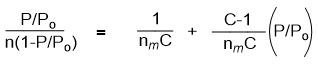
Where n = amount of N2 gas adsorbed, P = pressure of N2, Po = saturation pressure of N2
C = BET constant and nm = monolayer capacity.
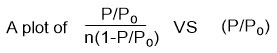
Will give a straight line graph with intercept = 1/nmC and slope = C-1/nmC.
The apparent surface area of a MOF can then be estimated using the plot. A linear region is selected based on Rouquerol et al.167 proposed criteria which are (a) the ‘‘C’’ must be positive,
(b) n(1-P/Po) should increase in a monotonic manner with (P/Po), the monolayer capacity (nm) should correspond to pressure within the limit of the data, and (d) the calculated value for the monolayer formation [1/(√C +1)] should be approximately equal to (P/Po) at the monolayer capacity.
Thus from such a plot, the intercept and slope from the linear region as well as the BET area (apparent surface area), nm and ‘‘C’’ can be obtained. In some publications, the empirical explanation for the application of BET theory with MOF has been detailed, including some computationally made isotherms for flawless (in silico) MOF structures in which absolute SBET can be independently calculated or estimated. 35,162–164,168
Information such as pore volume and pore size distribution of a MOF can also be obtained from such an isotherm although with some caution.35,158,169 The pore volume and pore size distribution of a MOF can be analysed using models such as density functional theory (DFT) or the Barrett-Joyner-Halenda method170 amongst others.
Nuclear Magnetic Resonance (NMR) Spectroscopy
NMR spectroscopy can also be utilized for the determination of the purity of MOF, linker- metal ratio, unused modulators a well as the presence or absence of solvent after activation.99 Many MOFs are known to be insoluble in common NMR solvents and so for the analysis of a MOF sample, the sample must first be digested before a spectrum can be obtained.171 The conventionally used approach for the digestion of a MOF for the purpose of NMR analysis involves the addition of D2SO4 (5-10 drops) to the sample (1-2 mg) followed by sonication of the mixture until the sample disperses in the acid. Following the sample digestion process, about 0.5 ml of DMSO-d6 can be added to the mixture to dilute and completely dissolve the sample. Sometimes sonication and heating may be required after the addition of DMSO-d6. For the analysis of the data collected to have meaning, the sample must be completely dissolved.172 However, if poor dissolution of MOF sample is observed following the procedure described, then less MOF sample and more acid can be used as necessary. Alternatively, instead of using D2SO4, 0.1 M NaOD (dilution of 40 wt % NaOD with D2O), hydrofluoric acid diluted with D2O can be used also for the digestion of MOF materials for NMR spectroscopy analysis.173
Solid-State NMR (SS-NMR) spectroscopy has also been utilized for the analysis of MOFs, especially in a bid to investigate the local chemical environment in a MOF.174,175 The SS-NMR technique has been successfully used for the qualitative analysis of the chemical state of some functional group such as the oxidation state of phosphorus atom inside a MOF.176–180 The method can also be used to gain insight about the supramolecular interactions as well as kinetics of small molecular species docking inside a MOF.181
Gas Adsorption Measurements
One problem associated with carbon capture and storage (CCS) is that the saturated adsorption measurement of CO2 near room temperature or at room temperature and high pressure are directly connected to the maximum capacity of adsorption of MOFs for CO2.3 The sum of the pore volume of MOFs is fundamentally proportional to the volume of CO2 that can be adsorbed at high pressure which strongly correlates with the SBET of MOFs as discussed above.
Gravimetric and volumetric methods can both be used for the measurement of gas adsorption in MOFs.156,160,182–184 The gravimetric method involves calculation in terms of mass differences between the mass of adsorbed gas in MOFs by means of highly-sensitive balances100,185,186 whereas the volumetric technique entails the measurement of pressure changes as the MOF adsorbs gases in a fixed volume.184,185 Both techniques have their pros and cons. For example, the result from the gravimetric technique can be affected drastically by impurities stemming from the gas source whereas the volumetric method suffers mostly from accumulative errors.184,185 However, the volumetric method has the advantage of easy operation as well as availability of equipment.
Organic Linkers
The synthesis of MOFs requires the presence of an organic ligand that coordinates with metal ions. The organic connectors are typically carboxylate (ditopic, tritopic, tetratopic, hexatopic or octatopic), heterocyclic-pyridyl linkers (ditopic and polytopic)187 or phosphonate linkers.20
Ditopic Carboxylate Linkers
Ditopic carboxylate connectors have been used extensively for the synthesis of MOFs because of their ready accessibility and well defined structures in combination with secondary building units (SBUs). Ditopic carboxylate linkers can form a variety of structural units such as 4-connected paddle-wheel clusters, octahedral clusters, trigonal-prismatic clusters, 12-connected clusters, and infinite chain clusters.
The same reaction starting materials (metal ions and organic linkers) can give rise to different crystal structures due to variations in reaction conditions. For example, MOF-5 [Zn4O(BDC)3.(DMF)8 (C6H5Cl)] was solvothermally synthesised by the reaction of a ditopic organic linker – 1,4-benzenedicarboxylate (BDC) with zinc nitrate – Zn(NO3)2.6H2O.5 But when trimethylamine-toluene was slowly allowed to diffuse at room temperature into an N,Nˈ-dimethylformamide (DMF)-toluene solution containing Zn(NO3)2, and BDC, colourless prism-shaped crystals of Zn(BDC)(DMF)(H2O) was obtained instead of MOF-5.88 The Zn(BDC).(DMF)(H2O) is a 2-D sheet whereas MOF-5 is a 3-D framework structure.
Examples of a ditopic linker incorporated into 4-connected paddle wheel clusters are found in MOF-118 and MOF-601.188 MOF-118 is a 2-D sheet synthesised by the use of a ditopic linker – 4,4ˈ-biphenyldicarboxylate (BPDC) and copper (II) acetate [Cu2(CH3COO)4] as the source of the metal ion. Copper acetate has the capability to assume the paddle-wheel structure with two solvent molecules completing its coordination sphere. MOF-601 is a 3-D MOF obtained using 2,2ˈ-dicyano-4,4ˈ-biphenyldicarboxylate (CNBPDC). Furthermore, 2,2ˈ-dihydroxy-1,1ˈ-binaphthalene-5,5ˈ- dicarboxylate (5,5ˈ-BDA) was used by Tanaka and co-workers90 for the preparation of a chiral MOF [Cu2(5,5ˈ-BDA)2(H2O)2].MeOH.2H2O, using Cu(NO3)2 in aqueous MeOH solution by the slow diffusion method of MOF synthesis as shown below in Scheme 1.
 |
Scheme 1: Preparation of a chiral MOF via slow diffusion.90 |
Some of the ditopic ligands used in the literature for the synthesis of MOFs are shown in Figure 3.
 |
Figure 3: Some ditopic carboxylate linkers used for the synthesis of MOFs |
Tritopic Carboxylate Linkers
A variety of tritopic carboxylate linkers such as those shown in Figure 4 have been used for the synthesis of MOFs. For example, MOF-177 with SBET of 4,500 m2/g was synthesised solvothermally using the octahedral Zn4O(CO2)6 cluster with the 1,3,5-benzenetricarboxylate (BTC) linker.159 While MIL-100(Cr) was assembled with Cr3O(CO2)6 cluster and BTC.189 The network of MIL-100 was reported to possess two kinds of mesoporous cages with accessible cage diameters of 25 and 29 Å. HKUST-1 (also known as MOF-199)190 with SBET = 692.2 m2/g was also synthesised with BTC and a dicopper paddle wheel SBU as the metal node.153 A good number of isoreticular MOFs have also been prepared using elongated tritopic carboxylate linkers. For example, meso-MOF-1 was synthesised using 4,4′,4”-s-triazine-1,3,5-triyltri-p-aminobenzoate (TATAB) as linker.191 PCN-6 was prepared with Cu(NO3)2.2.5H2O and 4,4′,4”-s-triazine-2,4,6-triyl-tribenzoate (TATB).192 MOF-399 has a void fraction of (94%) and density of (0.126 g/cm3) the second lowest after (NU-1301 = 0.124 g/cm3),193 was prepared by the use of a tritopic carboxylate linker (BBC) and Cu2(CO2)4 cluster.190 MOF-143 and MOF-338 were synthesised with BTB and TAPB respectively using the Cu2(CO2)4 cluster.190 Furthermore, MOF-180 (porosity = 89%) and MOF-200 (porosity = 90%) were prepared by the use of BTE and BBC respectively.118 Biphenyl-3,4ˈ,5-tricarboxylate (BHTC) has been used for the synthesis of UMCM-150 (UMCM = University of Michigan crystalline material) with Cu3(CO2)6 cluster as the source of metal node.194 The UMCM-150 was reported to have an apparent SBET of 2300 m2/g and Langmuir surface area of 3100 m2/g as well as a CO2 uptake of 4.68 mmol/g at 273 K/ 1 bar.194 Duan et al. prepared NJU-Bai3,195 by the use of 5-(4-carboxybenzoylamino)-isophthalate (CAIA) as a tritopic carboxylate linker and CuCl2.2H2O as the source of metal ion. It was reported that the presence of the amide group in CAIA extended the length of the cell as well as providing amide groups on the surfaces of the pores of NJU-Bai3, which enhanced the uptake (6.21 mmol/g at 273 K/ 1 bar) and selectivity of CO2 over other flue gas molecules.
 |
Figure 4: Some tritopic carboxylate linkers used for the preparation of MOFs. |
Tetratopic Carboxylate Linkers
Tetratopic carboxylate connectors are good building units used for the construction of many MOFs, particularly those with tetrahedral geometry. Tetrahedral linkers are becoming more popular in the construction of MOFs because they possess full Td symmetry, the highest symmetry in a linker that is currently attainable through organic synthesis.187 High-symmetry, building units are preferred in the construction of MOFs for several reasons. Some of these reasons are: (I) they expedite the packing process of repeating units during the formation of crystallites,187,196–198 (II) tetrahedral connectors may assume the geometry of any Td subdivision such as T, C3, C2, Cs, and C1187,199 as shown in Figure 5, and as such give diversity in the structures of MOF materials, (III) the tetrahedral linkers by nature are 3-dimensional; hence, when they are used in the construction of framework materials, wide channels and/or large pores are likely to form.
 |
Figure 5: Symmetry elements of a Td symmetry. |
The porosity, stability and the possibility of interpenetration in MOF materials are closely related to their topology.198,200,201 MOFs constructed by the combination of tetrahedral linkers, square planar linkers and (SBUs) such as hexagonal bipyramid clusters of metals are usually associated with network topologies such as fluorite (flu), platinum sulfide (pts) and alb/p as shown in Figure 6 187 These network topologies have the possibility of high porosity. The flu topology represents the combination of a tetrahedral linker with 8-connected cubic SBUs in the ratio of 2:1. The flu topology is potentially useful in MOFs because of its large cavity and non-interpenetrating nature.202 A framework containing flu topology does not suffer from self-interpenetration even when extended organic linkers are used.187,203
 |
Figure 6: Pictorial representation of some topologies associated with MOFs by the combination of tetrahedral linkers and SBUs 187 |
The pts topology on the other hand is by default the preferred topology formed by the combination of a 4-connected tetrahedral linker and a 4-connected square planar SBU in a 1: 1 ratio. For example, the combination of a dinuclear paddle-wheel SBU and a rigid tetrahedral connector generally leads to the formation of framework materials with pts topology.187,196 The alb/p topology involves the combination of 4-connected tetrahedral linker and 8-connected hexagonal bipyramidal SBUs.199 Unlike the flu topology, frameworks containing alb/p topology usually suffer from self-interpenetration.10,187
The combination of tetratopic carboxylate linkers such as 4,4′,4”,4”’-methanetetrayltetrabiphenyl- 4-carboxylate (MTBC) and 8-connected Zr6 clusters as SBU gave (M-TMBC, M = Zr or Hf)),204 and PCN-521,202 The SBET of PCN-521 was reported to be 3411 m2/g and are amongst the most porous MOFs assembled from tetratopic carboxylate linkers.202 MOF-11 [Cu2(ATC).6H2O] was prepared by Yaghi and co-workers via hydrothermal reaction of Cu(NO3)2 and a tetrahedral carboxylate linker, 1,3,5,7-adamantane tetracarboxylate (ATC).205 MOF-11 was reported to possess a permanent porosity as well as a Langmuir surface area and pore volume of 650 m2/g and 0.20 cm3/g respectively. However, when 4,4′,4”,4”’-methanetetrayltetrabenzoate (MTB) which is a longer tetrahedral connector was solvothermally reacted with a di-zinc paddle-wheel as SBU, MOF-36 [Zn2(MTB)(H2O)2.(DMF)6(H2O)5] was formed.206
A tetratopic carboxylate linker based with silicon as the central atom has also been used for the synthesis of MOFs. For example, IMP-8Cd [Cd2(L)(H2O)2].(DMA), IMP‑ 8Mn [Mn2(L)(H2O)2].(DMA)2.5, IMP9 [Cu2(L)(H2O)2].(DMA)12, IMP‑10 [Me2NH2]2[Cd3(L)2(H2O)2].(DMA)8(H2O)8, IMP-11 [Me2NH2]2[Zn3(L)2].(DMF)6, and IMP-12 [Me2NH2]2[Zn3(L)2].(DMF)3 were prepared solvothermally by Davies and co-workers9 by the use of 4,4′,4”,4”’-tetrakis-carboxylatephenylsilane (L = TCPS) with appropriate SBUs and solvent combination. In addition, PCN-512 was prepared by solvothermal method using TCPS and copper nitrate [Cu(NO3)2·2.5H2O].199 The PCN-512 was reported to exhibit 72.7% calculated solvent accessibility volume and an SBET of 601 m2/g. Furthermore, TCPS also reacted solvothermally with zinc nitrate in DEF at 85 °C to give PCN-511, Zn3(HTCPS3−)2,199 with an SBET of 702 m2/g and a solvent accessible volume of 45.6%. PCN-511/IMP-11 were reported to possess a solvent accessible volume and SBET of 48.4% 9 and 1284 m2/g 187 respectively after activation using a freeze-drying approach. A semi-rigid tetratopic carboxylate linker N,N,N’,N’-tetrakis(4-carboxyphenyl)- 1,4-phenylenediamine (TCPPDA) also reacted under solvothermal conditions with Cu(NO3)2.2.5H2O in dimethyl sulfoxide (DMSO) resulting in the formation of a MOF with pts topology.207 The Langmuir surface area of this MOF was reported to be 627 m2/g and to have a hydrogen storage capacity of 14 mg/g at 77 K/ 1 bar. Furthermore, PCN-46 was synthesised using 5,5′-(buta-1,3-diyne-1,4-diyl)diisophthalate (BDIP) and a copper salt.208 The SBET and pore volume of PCN-46 were reported to be 2500 m2/g and 1.012 cm3/g respectively. MOF PCN-14 was synthesised with another tetratopic carboxylate linker [5,5′-(anthracene-9,10-diyl)diisophthalate (ADIP)] and a dicopper paddlewheel cluster.209,210 The PCN-14 was reported to possess an SBET and density of 2000 m2/g and 0.829 g/cm3 respectively.211 PCN-12 was synthesised under solvothermal reaction conditions by Wang et al.212 using a tetratopic carboxylate linker 5,5′-methylene-di-isophthalate (MDIP) with Cu(NO3)2.2.5H2O in DMA. PCN-12 was reported to possess a hydrogen uptake of 3.05 wt.% at 77 K and 1 bar. Furthermore, Wenzel et al. also used 5,5′-(dimethylsilanediyl)diisophthalate (DMSDIP) a tetratopic carboxylate linker for the construction of UHM-3 (PCN-12-Si).21 The PCN-12-Si was reported to have a SBET of 2430 m2/g as well as a H2 uptake of 2.6 wt at 77K and 1 bar. In addition, Frahm et al. used an extended silicon-based tetratopic linker 4′,4”-(dimethylsilanediyl)bis([1,1′-biphenyl]-3,5-dicarboxylate) (SBBIP) and a copper paddle-wheel motif for the synthesis of UHM-6.213 MOF UHM-6 was reported to possess a SBET and specific microporous volume of 1200 m2/g and 0.48 cm3/g respectively. In addition, UHM-6 was reported to show a CO2 uptake of 3.3 mmol/g at 273 K and 1 bar after activation.
Some tetratopic carboxylate connectors used for the synthesis of MOFs are depicted in Figure 7.
 |
Figure 7: Some tetratopic carboxylate linkers used for the synthesis of MOFs. |
Hexatopic and Octatopic Carboxylate Linkers
Hexa-topic, octa-topic and other carboxylate linkers have been also used for the synthesis of MOFs.187 For example, a semi-rigid hexatopic linker 5,5′,5”-[1,3,5-Benzene-triyltris(carbonylimino)]tris-1,3-benzenedicarboxylate was used in the construction of a MOF consisting of a (3, 24)-network topology.214 In addition, a series of isoreticular MOFs such as (PCN-61, -66, -69 and -610) were constructed using hexatopic carboxylate linkers [5,5′,5′′- benzene-1,3,5-triyltris(1-ethynyl-2-isophthalate) (BTEI) and 5,5′,5′′- (4,4′,4′′-nitrilotris(benzene-4,1-diyl)tris(ethyne-2,1-diyl))triisoph-thalate (NTEI)] and other similar linkers with a dicopper paddle-wheel precausors.215–217 MOF NU-110E was constructed solvothermally by the reaction of 5,5′,5′′-(((benzene-1,3,5-triyl-tris(ethyne-2,1-diyl))-tris(benzene-4,1-diyl))tris(ethyne-2,1-diyl))triisophthalate (TTEI) and Cu(NO3)2 in DMF-EtOH-HCl at 75 °C.113 The NU-110E was reported to show a high experimental SBET of 7140 m2/g. 113
MOFs constructed using octatopic carboxylate linkers are rare as a result of synthetic challenges. Frameworks constructed with long linkers often prefer to form interpenetrated structures,187,196 but construction using octahedral connectors seems to discourage interpenetration possibly as a result of connectivity. Irrespective of these observations, MOFs such as UTSA-33a,218 and UTSA-33b,219 were constructed by octatopic carboxylate linkers (4′,5′-bis(3,5-dicarboxylatophenyl)-[1,1′:2′,1”-terphenyl]- 3,3”,5,5”-tetracarboxylate) (BDPPC) and zinc and dicopper paddle-wheel clusters respectively. In addition, Fang and co-workers220 used an octadentate carboxylate linker 5,5′,5”,5”’-silanetetrayltetraisophthalate (STIP) with different metal ions to give three different MOFs which possessed interesting structures and properties. Furthermore, Tan et al.221 used extended tetrahedral octatopic carboxylate linkers 4′,4”’,4””’,4”””’-methanetetrayltetrakis(([1”,1”’-biphenyl]-3,5-dicarboxylate)) (MTBPC) to construct MOF NOTT-140.221 The estimated apparent SBET of NOTT-140 was reported to be 2620 m2/g. Some hexatopic and octatopic carboxylate linkers used for the construction of MOFs are shown in Figures 8 and 9.
 |
Figure 8: Some hexatopic carboxylate linkers used for the construction of MOFs. |
 |
Figure 9: Some octatopic carboxylate linkers used for the construction of MOFs. |
N-Heterocyclic Linkers
The strength of the bond formed between nitrogen and transition metal ions is strong. 222 Thus, organic linkers containing N donor(s) (azole and pyridine) derivatives have been employed in the synthesis of MOFs. The N-heterocyclic linkers may be ditopic, tritopic, tetratopic or polytopic. Azole-based linkers are used for the construction of MOFs because of their ability to bind strongly with metal ions. The azoles are five-membered aromatic N-heterocycles such as imidazoles, pyrazoles, 1, 2,4-triazole, 1,2,3-triazole and tetrazole. The deprotonation of azoles through the decomposition of amide solvents such as N,N-dimethylformamide (DMF) or N,N-diethylformamide (DEF) used in solvothermal reactions gives rise to azolates.187,223,224 When metal ions react with azolates, Metal-Azolate-Metal bonds are formed.223 Metal-Imidazolate Frameworks (also known as Zeolitic Imidazolate Frameworks (ZIFs), ZIF-1, ZIF-2, ZIF-3 to ZIF-12 series are examples of MOFs obtained from N-heterocyclic linkers with metal ions.223 Many ZIFs have been constructed with metal ions such as Fe2+, Co2+, Cu2+, or Zn2+ which resulted in the formation of frameworks that are topologically isomorphous to zeolites.223 For example, it has been reported that when two metal ions react with imidazolates (Ims) to form (M-Im-M), the bridging angle between the imidazolate and the metals is coincidentally similar to the Si-O-Si angle found in zeolites (145°) aluminosilicate-based materials,223,224 as shown in Figure 10.
 |
Figure 10: The bridging angles in (a) metal Im (b) zeolites223,224 |
For example, ZIF-8 [Zn(MeIm)2] and ZIF-11 [Zn(PIm)2] were constructed by the use of 2-methylimidazolate and benzimidazolate respectively. These two ZIFs were reported to display permanent porosity and exceptional thermal stability up to 500 °C. In addition, ZIF-8 was reported to show outstanding chemical stability at reflux in organic solvents as well as in aqueous alkaline solutions.224 ZIF-95 [Zn(cbIm)2] and ZIF-100 [Zn20(cbIm)39(OH)], (cbIM = chlorobenzimidazolate) are also MOFs obtained from N-heterocyclic linkers.225 ZIF-95 and ZIF-100 were reported to have permanent porosity as well as Langmuir surface areas of 1240 and 780 m2/g respectively. 3,3,5,5-Tetramethyl-4,4-bipyrazolate (Me4Bpz) was utilized for the construction of MOF Ag2(Me4bpz)226 which was reported to show reversible sorption properties as well as possess an SBET of 240 m2/g.
One of the limitations associated with the use of azolates for the construction of MOFs is their short bridging lengths. Thus, longer pyrazole-based linkers are also used in the construction of MOF materials. For example, four pyrazolate-bridged MOFs M3(btp)2, where M = Ni, Cu, Zn and Co have been constructed using 1,3,5-tris(1H-pyrazol-4-yl)benzene as a source of N-heterocyclic linker.227 it was reported that the SBETs of these four MOFs after activation were 1650, 1860, 930 and 1027 m2/g respectively. In addition, Zn3(btp)2 was reported to show high thermal stability up to 500 °C as well as chemical stability in boiling aqueous solution. The Tritopic tetrazolate linker 1,3,5-benzenetristetrazolate (BTT) has also been employed for the construction of a series of MOF materials.228–230 In these MOFs, the BTT coordinated with the metal ions through its two middle N atoms. Furthermore, Long and co-workers, treated CuCl2 with a tetrahedral N-heterocyclic linker tetrakis(4-tetrazolylphenyl)methane) (ttpm) which resulted in the formation of MOF Cu4(ttpm)2.0.7CuCl2, which upon activation using solvent exchange approach exhibited an SBET of 2506 m2/g.231 Davies and co-workers have also used tetrahedral tetrakis(4-tetrazolylphenyl)silane ligand (H4TTPS) and CuCl2·2H2O for the synthesis of [H(Cu4Cl)(ttps)2(DMF)4]·18DMF (IMP-16).232
Dipyridyl linkers have also been used in the literature for the synthesis of MOF materials. However, as they are neutral components, another anionic ligand or counterion is required to balance out the positive charge on the metal centres. For example, Bunz and co-workers constructed a series of MOFs using the tetrahedral pyridine linker [tetrakis(4-(pyridin-4-ylethynyl)phenyl)silane].91 This series of MOFs was reported to show a variety of topologies, interpentrations as well as porosities. Mandal and co-workers used a carboxylate silicon-based linker, 4,4’-bipyridine as a co-connector and Mn(II) paddle-wheel subunit to construct {[Mn2(O2CC6H4Si(CH3)2C6H4CO2)2(4,4′-bpy)]}n.233 Mocanu et al.16 used 1,3,5,7-tetrakis{4-(4-pyridyl)phenyl}adamantane) and copper (II) ions to construct a 3-D MOF [CuL1(H2O)2](BF4)2·8H2O. This MOF was reported to show a 4-fold interpenetration with a pts topology. A zinc(II) MOF [Zn2(l 4-o-pda)2(l -abpy)]n based on flexible o-phenylenediacetate and rigid 4,4′-azobis(pyridine) ligands was constructed by Tabak and co-workers.15 This MOF was reported to be thermally stable up to 300 °C. Figure 11,shows some of the N-heterocyclic linkers used for the synthesis of MOF materials.
 |
Figure 11: Some N-heterocyclic linkers used for the construction of MOFs |
Most of the carboxylate and N-heterocyclic linkers used for the construction of MOF materials are based on carbon centres as well as commercially available connectors. Silicon-based connecting units are scarce compared to their carbon analogues but silicon-centred linkers are more convenient to prepare through metathesis compared to their carbon analogues.234 To this end, it is still desirable to design novel linkers with tailored dimensionality or pendant functional groups so as to have a control of the physicochemical properties of the resultant framework materials. Several synthetic routes have been employed for the syntheses of varieties of rigid aryl systems based on silicon or boron centres with carboxylate or pyridyl pendants.6,9,240–244,17,21,199,235–239
Conclusion
We have successfully reviewed the subject matter of MOFs. The design methodologies, activation and characterisation of MOFs and some applications. We anticipate that this review article will help researchers, industrialists as well as academics in their quest for standard literature.
Acknowledgement
We thankfully acknowledge the financial support given to us by the Nigerian Government through the Petroleum Technology Development Fund (PTDF), Nigeria, as well as the Rivers State University, Port Harcourt Nigeria
Conflicting Interest
The authors declare that we do not have any conflicting interest.
Funding Sources
There is no funding source.
References
- Zhou, H.; Long, J. R.; Yaghi, O. M. Am Chem Soc. 2012;112:673-674. doi:10.1021/cr300014x
CrossRef - Rosi, N.L.; Eddaoudi, M.; Kim, J.O. CrystEngComm. 2002;4(68):401-404. doi:10.1039/B203193K
CrossRef - Li, J.; Sculley, J.; Zhou, H.. Chem Rev. 2012;112:869-932. doi:10.1021/cr200190s
CrossRef - Bull, O.S.; Bull, I.; Amadi, G.K.; Odu, C.O. J Appl Environ Manag. 2022;26 (1):145-179. doi: https://dx.doi.org/10.4314/jasem.v26i1.22 Open
CrossRef - Li, H.; Eddaoudi, M.; O’Keeffe, M.; Yaghi, O.M. Nature. 1999;(402):276-279. doi:10.1038/46248
CrossRef - Liu, C.; Ma, Y.Q.; Tian, H.R.; Chao-Yingb, G.A.O.; Li, Y.H. Chinese J Struct Chem. 2017;36(4):654─660. doi:10.14102/j.cnki.0254-5861.2011-1347
- Vlad, A.; Zaltariov.; M.F.; Shova, S.; Novitchi, G.; Train, C.; Cazacu, M.. RSC Adv. 2016;6(44):37412-37423. doi:10.1039/C6RA03969C
CrossRef - Davies, R.P.; Less, R.J.; Lickiss, P.D, White, A.J.P. Dalt Trans. 2007;3(24):2528-2535. doi:10.1039/b705028c
CrossRef - Davies, R.P.; Less, R.; Lickiss, P.D.; Robertson, K.; White, A.J.P. Cryst Growth Des. 2010;10(10):4571-4581. doi:10.1021/cg1008768
CrossRef - Wen L.; Cheng, P.; Lin, W.. Chem Sci. 2012;3(7):2288-2292. doi:10.1039/c2sc20172k
CrossRef - Guo, T.; Yang, X.; Li, R.; Liu, X.; Gao, Y.; Dai, Z.; Fang, M,; Liu, H.; Wu, Y.. J Solid Chem. 2017;253:129-138. doi:10.1016/j.jssc.2017.05.011
CrossRef - Chen, S.; Qiao, R.; Sheng, L.; Yang S.; Liu, Z.. CrystEngComm. 2013;639(10):1808-1814. doi:10.1002/zaac.201300189
CrossRef - Goodgame, D.M.L.; Lickiss, P.D.; Rooke, S.J.; White, A.J.P.. Inorganica Chim Acta. 2003;343:61-73. doi:10.1016/S0020-1693(02)01207-0
CrossRef - Goodgame, D.M.L.; Lickiss, P.D.; Rooke, S.J; White, A.J.P. 2001;324:218-231. doi:10.1016/S0020-1693(01)00608-9
CrossRef - Günay, G.; Yeşilel, O.Z.; Erer, H.; Keskin, S.; Tabak, A. Polyhedron. 2015;100:108-113. doi:10.1016/j.poly.2015.07.017
CrossRef - Mocanu, T.; Pop, L.; Shova, S.; Grosu, I.; Andruh, M. 2017;19(1):27-31. doi:10.1039/C6CE02146H
CrossRef - Schütrumpf, A.; Kirpi, E.; Bulut, A. Morel, F.L.; Ranocchiari, M.; Lork, E.; Zorlu, Y.; Grabowsky, S.; Yucesan, G.; Beckmsnn, J. Cryst Growth Des. 2015;15(10):4925-4931. doi:10.1021/acs.cgd.5b00811
CrossRef - Ai, J.; Min, X.; Gao, C.; Tian, H.; Dang, S.; Sun, Z. Dalt Trans. 2017;46(20):6756-6761. doi:10.1039/c7dt00739f PM
CrossRef - Zaręba, J.K.. Inorg Chem Commun. 2017;86:172-186. doi:10.1016/j.inoche.2017.10.013
CrossRef - Firmino, A.D.G.; Figueira, F.; Tomé, J.P.C.; Paz, F.A..;, Rocha, J.. Coord Chem Rev. 2018;355:133-149. doi:10.1016/j.ccr.2017.08.001
CrossRef - Wenzel, S.E.; Fischer, M.; Hoffmann, F.; Fröba, M.. Inorg Chem. 2009;48(14):6559-6565. doi:10.1021/ic900478z
CrossRef - Liu, Y.; Su, J.; Li, W.; Wu, J. Inorg Chem. 2005;44(11):3890-3895. doi:10.1021/ic0501418
CrossRef - Côté, A.P.; Shimizu, G.K. Inorg Chem. 2004;43(21):6663-6673. doi:10.1021/ic0491229
CrossRef - Gangu, K.K.; Maddila, S.; Mukkamala, S.B.; Jonnalagadda, S.B.. Inorganica Chim Acta. 2016;446:61-74. doi:10.1016/j.ica.2016.02.062
CrossRef - Rubio-Martinez, M.; Avci-Camur, C.; Thornton, A.W.; Imaz, I.; Maspoch, D.; Hill, M.R.. Chem Soc Rev. 2017;46(11):3453-3480. doi:10.1039/C7CS00109F
CrossRef - Ren, J.; Dyosiba, X.; Musyoka, N.M,; Langmi, H.W.; Mathe, M.; Liao, S.. Coord Chem Rev. 2017;352:187-219. doi:10.1016/j.ccr.2017.09.005
CrossRef - Fan, J.; Shu, M.H.; Okamura, T.; Li, Y.; Sun, W.; Tang, W.; Ueyama, N. New J Chem. 2003;27(9):1307-1309. doi:10.1039/b306876p
CrossRef - Çolak, A.T.; Pamuk, G.; Yeilel, O.Z.; Yüksel, F.. Solid State Sci. 2011;13(12):2100-2104. doi:10.1016/j.solidstatesciences.2011.08.006
CrossRef - Davies, R.P.; Lickiss, P.D.; Robertson, K.; White, A.J.P. CrystEngComm. 2012;14(3):758. doi:10.1039/c1ce06091k
CrossRef - Schaate, A.; Roy, P.; Godt, A.; Lippke, J.; Waltz, F.; Wiebcke, M.; Behrens, P. Chem – A Eur J. 2011;17(24):6643-6651. doi:10.1002/chem.201003211
CrossRef - Vermoortele, F.; Bueken, B.; Le Bars, G.; Van de Voorde, B.; Vandichel, M.; Houthoofd, K.; Vimont, A.; Daturi, M.; Waroquier, M.; Van Speybroeck. V.; Kirschhock, C.; De Vos, D.E. J Am Chem Soc. 2013;135(31):11465-11468. doi:10.1021/ja405078u
CrossRef - Wu, H.; Chua.; Y.S.; Krungleviciute, V.; Tyagi, M.; Chen, P.; Yildirim, T.; Zhou, W. J Am Chem Soc. 2013;135(28):10525-10532. doi:10.1021/ja404514r
CrossRef - Shearer, G.C.; Chavan, S.; Bordiga, S.; Svelle, S.; Olsbye, U.; Lillerud, K.P. Chem Mater. 2016;28(11):3749-3761. doi:10.1021/acs.chemmater. 6b00602
CrossRef - Katz, M.J.; Brown, Z.J.; Colón, Y.J.; Siu, P.W.; Scheidt, K.A.; Snurr, R.Q.; Hupp, J.T.; Farha, O. K. Chem Commun. 2013;49(82):9449-9451. doi:10.1039/c3cc46105j
CrossRef - Howarth, A.J.; Peters, A.W.; Vermeulen, N.A.; Wang, T.C.; Hupp, J.T.; Farha, O.K.. Chem Mater. 2017;29(1):26-39. doi:10.1021/acs.chemmater.6b02626
CrossRef - Natarajan, S.; Mandal, S.; Mahata, P.; Vandavasi, K.; Ramaswamy, P.; Banerjee, A.; Paul, A.K,; Ramya, K.V. J Chem Sci. 2006;118(6):525-536. doi:10.1007/BF02703950
CrossRef - Mulyati, T.A.; Ediati, R.; Nadjib, M. J Proc. 2014;1:8-13. DOI: http://dx.doi.org/10.12962/j23546026.y2014i1.415
CrossRef - Mingos, D.M.P.; Baghurst, D.R. Chem Soc Rev. 1991;20(1):1-47. doi:10.1039/cs9912000001
CrossRef - Oliver, K.C. Chem Soc Rev. 2008;37(6):1127-1139. doi:10.1039/b803001b
CrossRef - Klinowski, J.; Almeida, P. F.; Silva, P.; Rocha, J. Dalt Trans. 2011;40(2):321-330. doi:10.1039/C0DT00708K
CrossRef - Surati, M.A.; Jauhari, S.; Desai, K.R. Arch Appl Sci Res. 2012;4(1):645-661.
- Ni, Z. Masel, R.I. J Am Chem Soc. 2006;128(38):12394-12395. doi:10.1021/ja0635231
CrossRef - McKinstry, C.; Cussen, E.;J. Fletcher, A.J.; Patwardhan, S.V.; Sefcik, J.. Chem Eng J. 2017;326:570-577. doi:10.1016/j.cej.2017.05.169
CrossRef - Choi, J.Y.; Kim, J. Jhung, S.H.; Kim, H.; Chang, J.; Chae, H.K. Bull Korean Chem Soc. 2006;27(10):1523-1524. doi:10.5012/bkcs.2006.27.10.1523
CrossRef - Taddei, M.; Steitz, D.A.; Van-Bokhoven, J.A.; Ranocchiari, M. Chem – A Eur J. 2016;22(10):3245-3249. doi:10.1002/chem.201505139
CrossRef - Abhyankar, N.; Lee, M.; Foley, M.; Choi, E.S.; Strouse, G.; Dalal, N.S. Phys status solidi – Rapid Res Lett. 2016;10(8):600-605. doi:10.1002/pssr.201600175
CrossRef - Akhbari, K.; Morsali, A.; Retailleau, P. Ultrason Sonochem. 2013;20(6):1428-1435. doi:10.1016/j.ultsonch.2013.03.013
CrossRef - Yang, D.A.; Cho, H.Y, Kim, J.; Yang, S..;, Ahn, W.S. Energy Environ Sci. 2012;5(4):6465-6473. doi:10.1039/C1EE02234B
CrossRef - Jung, D.W.; Yang, D.A.; Kim, J.; Kim, J.; Ahn, W.S. Dalt Trans. 2010;39(11):2883-2887. doi:10.1039/b925088c
CrossRef - Son, W.J.; Kim, J.; Kim, J.; Ahn, W.S. Chem Commun. 2008;47(47):6336-6338. doi:10.1039/b814740j
CrossRef - Pezeshkpour, V.; Khosravani, S.A.; Ghaedi, M.; Dashtian, K.; Zare, F.; Sharifi, A.; Jannesar, R.; Zoladl, M. Ultrason Sonochem. 2018;40(September 2017):1031-1038. doi:10.1016/j.ultsonch.2017.09.001
CrossRef - Haque, E.; Khan, N.;Park, H.J.; Jhung, S.H.. Chem – A Eur J. 2010;16(3):1046-1052. doi:10.1002/chem.200902382
CrossRef - Abuzalat, O.; Wong, D.; Elsayed, M.; Park, S.; Kim, S. Ultrason Sonochem. 2018;45(December 2017):180-188. doi:10.1016/j.ultsonch.2018.03.012
CrossRef - Mueller, U.; Schubert, M.; Teich, F.; Puetter, H.; Schierle-Arndt, K.; Pastré, J. J Mater Chem. 2006;16(7):626-636. doi:10.1039/B511962F
CrossRef - Gaab, M,; Trukhan, N.; Maurer, S. Gummaraju, R,; Müller, U. Microporous Mesoporous Mater. 2012;157:131-136. doi:10.1016/j.micromeso.2011.08.016
CrossRef - Schlesinger, M.; Schulze, S.; Hietschold, M.; Mehring, M.. 2010;132(1-2):121-127. doi:10.1016/j.micromeso.2010.02.008
CrossRef - Hartmann, M.; Kunz, S.; Himsl, D.; Tangermann, O.; Ernst, S.; Wagener, A.. Langmuir. 2008;24(16):8634-8642. doi:10.1021/la8008656
CrossRef - Yang, H.M.; Song, X.L.; Yang, T.L.; Liang, Z.H.; Fan, C.M.; Hao, X.G. RSC Adv. 2014;4(30):15720-15726. doi:10.1039/C3RA47744D
CrossRef - Martinez, J. A.; Juan-Alcañiz, J.; Serra-Crespo, P.; Kapteijn, F.; Gascon, J. Cryst Growth Des. 2012;12(7):3489-3498. doi:10.1021/cg300552w
CrossRef - Campagnol, N.; Souza, E.R.; De-Vos, D.E.; Binnemans, K.; Fransaer, J. Chem Commun. 2014;50(83):12545-12547. doi:10.1039/C4CC05742B
CrossRef - Zhu, H.; Liu, H.; Zhitomirsky, I.; Zhu, S. Mater Lett. 2015;142:19-22. doi:10.1016/j.matlet.2014.11.113
CrossRef - Li, M.; Dincă, M. Chem Sci. 2014;5(1):107-111. doi:10.1039/C3SC51815A
CrossRef - Schäfer, P. vander-Veen, M.A.; Domke, K.F. Chem Commun. 2016;52(25):4722-4725. doi:10.1039/C6CC00534A
CrossRef - Al-Kutubi, H.; Gascon, J.; Sudhölter, E.J.R.; Rassaei, L. ChemElectroChem. 2015;2(4):462-474. doi:10.1002/celc.201402429
CrossRef - Li, M.; Dincǎ, M.. J Am Chem Soc. 2011;133(33):12926-12929. doi:10.1021/ja2041546
CrossRef - Li, W.J.; Tu, M.; Cao, R.; Fischer, R.A.. J Mater Chem A. 2016;4(32):12356-12369. doi:10.1039/C6TA02118B
CrossRef - Crawford, D.E.; Casaban, J. Adv Mater. 2016;28:5747-5754. doi:10.1002/adma.201505352
CrossRef - Garay, A.L.; Pichon,; A.; James, S.L. Chem Soc Rev. 2007;36(6):846-855. doi:10.1039/b600363j
CrossRef - Friščić, T. Chem Soc Rev. 2012;41(9):3493-3510. doi:10.1039/c2cs15332g
CrossRef - Boldyrev, V.V. Solid State Ionics. 1993;63-65(C):537-543. doi:10.1016/0167-2738(93)90157-X
CrossRef - Stolle, A.; Szuppa, T.; Leonhardt, S.E.S.; Ondruschka, B. Chem Soc Rev. 2011;40(5):2317-2329. doi:10.1039/c0cs00195c
CrossRef - Friščić, T. J Mater Chem. 2010;20(36):7599-7605. doi:10.1039/c0jm00872a
CrossRef - James, S.L.; Adams, C.J.; Bolm, C.; Braga, D.; Collier, P.; Friščić, T.; Grepioni, F.; Harris, K.D.M.; Hyett, G.; Jones, W.; Krebs, A.; Mack, J.; Maini, L.; Orpen, A.G.; Parkin, I.P.; Shearouse, W.C.; Steed, J.W.; Waddell, D.C. Chem Soc Rev. 2012;41(1):413-447. doi:10.1039/C1CS15171A
CrossRef - Braga, D.; Grepioni, F. Chem Commun. 2005;(29):3635-3645. doi:10.1039/b504668h
CrossRef - Pichon, A.; Lazuen-Garay, A.; James, S.L. CrystEngComm. 2006;8(3):211-214. doi:10.1039/b513750k
CrossRef - Pichon, A.; James, S.L. CrystEngComm. 2008;10(12):1839-1847. doi:10.1039/b810857a
CrossRef - Tanaka, S.; Kida, K.; Nagaoka, T.; Ota, T.; Miyake, Y. Chem Commun. 2013;49(72):7884-7886. doi:10.1039/c3cc43028f
CrossRef - Aakeröy, C.B.; Sinha, A.S.; Epa, K.N.; Spartza, C.L.; Desper, J. Chem Commun. 2012;48(92):11289-11291. doi.org/10.1039/C2CC36315A
CrossRef - Leng, K.; Sun, Y.; Li, X.; Sun, S.; Xu, W. Cryst Growth Des. 2016;16(3):1168-1171. doi:10.1021/acs.cgd.5b01696
CrossRef - Braga, D.; Curzi, M.; Johansson, A.; Polito, M.; Rubini, K.; Grepioni, F. Angew Chemie – Int Ed. 2006;45(1):142-146. doi:10.1002/anie.200502597
CrossRef - Friščić, T.; Fábián, L.; CrystEngComm. 2009;11(5):743-745. doi:10.1039/b822934c
CrossRef - Klimakow, M.; Klobes, P.; Thünemann, A.F.; Rademann, K.; Emmerling, F. Chem Mater. 2010;22(18):5216-5221. doi:10.1021/cm1012119
CrossRef - Yuan, W.; Garay, A.L.; Pichon, A.; Clowes, R.; Wood, C.D.; Cooper, A.I.; James, S.L. CrystEngComm. 2010;12(12):4063-4065. doi:10.1039/c0ce00486c
CrossRef - Užarević, K.; Wang, T.C.; Moon, S.; Fidelli, A.M.; Hupp, J.T.; Farha, O.K.; Friščić, T. Chem Commun. 2016;52(10):2133-2136. doi:10.1039/C5CC08972G
CrossRef - Prochowicz, D.; Sokołowski, K.; Justyniak, I.; Kornowicz, A.; Fairen-Jimenez, D. Friščić, T. Lewiński, J. Chem Commun. 2015;51(19):4032-4035. doi:10.1039/C4CC09917F
CrossRef - Friščić, T.; Reid, D.G.; Halasz, I.; Stein, R.S. Dinnebier, R.E.; Duer, M.J. Angew Chemie – Int Ed. 2010;49(4):712-715. doi:10.1002/anie.200906583
CrossRef - Beldon, P.J, Fábián, L.; Stein, R.S.; Thirumurugan, A.; Cheetham, A.K.; Friščić, T. Angew Chemie – Int Ed. 2010;49(50):9640-9643. doi:10.1002/anie.201005547
CrossRef - Li, H.; Eddaoudi, M.; Groy, T.L.; Yaghi, O.M. J Am Chem Soc. 1998;120(33):8571-8572. doi:10.1021/ja981669x
CrossRef - Eddaoudi, M.; Kim, J.; O’Keeffe, M.; Yaghi, O.M. J Am Chem Soc. 2002;124(3):376-377. doi:10.1021/ja017154e
CrossRef - Tanaka, K.; Oda, S.; Shiro, M. Chem Commun. 2008;(7):820-822. doi:10.1039/B714083E
CrossRef - Geyer, F.L.; Rominger, F.; Vogtland, M.; Bunz, U.H.F. Cryst Growth Des. 2015;15(7):3539-3544. doi:10.1021/acs.cgd.5b00719
CrossRef - Zhang, W.; Yang, Y.; Zai, S.; Ng, S.W.; Chen, X. Eur J Inorg Chem. 2008;2(5):679-685. doi:10.1002/ejic.200701041
CrossRef - Liao, J.; Wu, P.; Huang, W. Cryst Growth Des. 2006;6(5):1062-1063. doi:10.1021/cg0504197
CrossRef - Dybtsev, D.N.; Chun, H.; Kim, K. ChemComm. 2004;3:1594-1595. doi: 10.1002/anie.200460712
CrossRef - Rubio-Martinez, M.; Batten, M.P.; Polyzos, A.; Carey, K.; Mardel, J.I.; Lim, K.; Hill, M.R. 2014;4:1-5. doi:10.1038/srep05443
CrossRef - Bennett, T.D.; Cheetham, A.K.; Fuchs, A.H.; Coudert, F. Nat Chem. 2016;9(1):11-16. doi:10.1038/nchem.2691
CrossRef - Sholl, D.S.; Lively, R.P. J Phys Chem Lett. 2015;6(17):3437-3444. doi:10.1021/acs.jpclett.5b01135
CrossRef - Férey, G.; Mellot-Draznieks, C.; Serre, C.; Millange, F.; Dutour, J.; Surble, S.; Margiolaki, I. 2040-2042. doi:10.1126/science.1116275
CrossRef - Kalinovsky, Y.; Cooper, NJ.; Main, M.J.; Holder, S.J.; Blight, B.A. Dalt Trans. 2017;46(45):15704-15709. doi:10.1039/C7DT03616G
CrossRef - Mondloch, J.E.; Karagiaridi, O.; Farha, O.K.; Hupp, J.T. Acc Chem Res. 2013;43:9258-9264. doi:10.1039/c3ce41232f
CrossRef - Cavka, J.H.; Jakobsen, S.; Olsbye, U.; Guillou, N.; Lambert, C.; Bordiga, S.; Lillerud, K.P. J Am Chem Soc. 2008;6:1-19. doi:10.1021/ja8057953
CrossRef - Abrahams, B.F.; Hoskins, BF.; Michail, D.M.; Robson, R. Nature. 1994;369(6483):727-729. doi:10.1038/369727a0
CrossRef - Eddaoudi, M.; Kim, J.; Rosi, N.; Vodak, D.; Wachter, J.; O’Keeffe, M.; Yaghi, O.M. Science (80- ). 2002;295(5554):469-472. doi:10.1126/science.1067208.
CrossRef - Mondloch, J.E.; Karagiaridi, O.; Farha, O.K.; Hupp, J.T. Acc Chem Res. 2013;43:9258-9264. doi:10.1039/c3ce41232f
CrossRef - Nelson, A.P.; Farha, O.K.; Mulfort, K.L.; Hupp, J.T. J Am Chem Soc. 2009;131(2):458-460. doi:doi:10.1021/ja808853q
CrossRef - Düren, T.; Millange, F.; Férey, G.; Walton, K.S.; Snurr, R.Q. J Phys Chem C. 2007;111(42):15350-15356. doi:10.1021/jp074723h
CrossRef - Lin, X.; Telepeni, I. Blake.; A.J. 2009;131(Ii):2159-2171. doi:10.1021/ja806624j
CrossRef - Yaws, C.L.; Richmond, P.C. William Andrew, ed. Thermophysical Properties of Chemicals and Hydrocarbons. Surface tension. ; 2009:686-781. doi:10.1016/B978-081551596-8.50026-2
CrossRef - Mondloch, J.E.; Karagiaridi, O.; Farha, O.K.; Hupp, J.T. CrystEngComm. 2013;15(45):9258-9264. doi:10.1039/c3ce41232f
CrossRef - Zhuang, W.; Ma, S.; Wang, X. Chem Commun. 2010;46(29):5223-5225. doi:10.1039/c0cc00779j
CrossRef - Meek, S.T.; Perry, J.J.; Teich-Mcgoldrick, S.L.; Greathouse, J.A.; Allendorf, M.D. Cryst Growth Des. 2011;11(10):4309-4312. doi:10.1021/cg201136k
CrossRef - Farha, O.K.; Yazaydin, A.Ö.; Eryazici, I. Nat Chem. 2010;2(11):944-948. doi:10.1038/nchem.834
CrossRef - Farha, O.K.; Eryazici, I.; Jeong, N.C.; Hauser, B.G.; Wilmer, C.E.; Sarjeant, A.A.; Snurr, R.Q. Nguyen, S.T.; Yazaydin, A.Ö.; Hupp, J.T. J Am Chem Soc. 2012;134(36):15016-15021. doi:10.1021/ja3055639
CrossRef - Bae, Y.S.; Dubbeldam, D.; Nelson, A.; Walton, K.S.; Hupp, J.T.; Snurr, R.Q. Chem Mater. 2009;21(20):4768-4777. doi:10.1021/cm803218f
CrossRef - Shultz, A.M.; Sarjeant, A.A.; Farha, O.K.; Hupp, J.T.; Nguyen, S.T. J Am Chem Soc. 2011;133(34):13252-13255. doi:10.1021/ja204820d
CrossRef - Shultz, A.M.; Farha, O.K.; Adhikari, D.; Sarjeant,. AA.; Hupp, J.T.; Nguyen, S.T. Inorg Chem. 2011;50(8):3174-3176. doi:10.1021/ic101952y
CrossRef - Wilmer, C.E.; Farha, O.K.; Yildirim, T.; Eryzici, I.; Krunggleviciute, V.; Sarjeant,. AA.; Snurr, R.Q.; Hupp, J.T. Energy Environ Sci. 2013;6(4):1158-1163. doi:10.1039/c3ee24506c
CrossRef - Furukawa, H.; Ko, N.; Go, Y.B.; Aratani, N.; Choi, S.B.; Yazaydin, A.O.; Snurr, R.Q.; O’Keeffe, M.; Yaghi, O.M. Science (80-). 2010;329(5990):424-428. doi:10.1126/science.1192160
CrossRef - Prasad, T.K.; Suh, M.P. Chem – A Eur J. 2012;18(28):8673-8680. doi:10.1002/chem.201200456
CrossRef - Song, X. Kim, T.K.; Kim, H.; Kim, D.; Jeong, S.; Moon, H.R.; Lah, M.S. Chem Mater. 2012;24(15):3065-3073. doi:10.1021/cm301605w
CrossRef - Koh, K.; Van, O.J.D.; Roy, S.; Wong-Foy, A.G.; Matzger, A.J. Chem Sci. 2012;3(8):2429-2429. doi:10.1039/c2sc20407j
CrossRef - An, J.; Farha, O.K.; Hupp, J.T.; Pohl, E.; Yeh, J.I.; Rosi, N.L. Nat Commun. 2012;3:604-606. doi:10.1038/ncomms1618
CrossRef - Han, D.; Jiang, F.L.; Wu, M.; Chen, L.; Chen, Q.; Hong, M.C. Chem Commun. 2011;47(35):9861-9863. doi:10.1039/c1cc12858b
CrossRef - Grünker, R.; Senkovska, I.; Biedermann, R.; Klein, N.; Lohe, M.R.;Muller, P.; Kaskel, S. Chem Commun. 2011;47(1):490-492. doi:10.1039/C0CC02273J
CrossRef - Deng, H.; Grunder, S.; Cordova, K.E, Science (80- ). 2006;(336):1757-1762.
CrossRef - Zhang, Z.; Wojtas, L.; Eddaoudi, M.; Zaworotko, M.J. J Am Chem Soc. 2013;135(16):5982-5985. doi:10.1021/ja4015666
CrossRef - Francis, A.W. J Phys Chem. 1954;58(12):1099-1114. doi:10.1021/j150522a014
CrossRef - Rey, L. Nature. 1990;345:185-186.
CrossRef - Ma, L.; Jin, A.; Xie, Z.; Lin, W. Angew Chemie – Int Ed. 2009;48(52):9905-9908. doi:10.1002/anie.200904983
CrossRef - Deville, S.; Saiz, E.; Nalla, R.K.; Tomsia, A.P. Science (80- ). 2006;311(2006):515-518. doi:10.1126/science.1120937
CrossRef - Zhao, D.; Cao, M. ACS Appl Mater Interfaces. 2015;7(45):25084-25093. doi:10.1021/acsami.5b05269
CrossRef - Li, Y.; Liu, Q.; Kang, D.; Gu, J.; Zhang, W.; Zhang, D. J Mater Chem A. 2015;3(42):21016-21022. doi:10.1039/C5TA04233J
CrossRef - Gaudillere, C.; Garcia-Fayos, J.; Serra, J.M. J Mater Chem A. 2014;2(11):3828-3833. doi:10.1039/c3ta14069e
CrossRef - He, Y.P.; Tan, Y.X.; Zhang, J. Inorg Chem. 2012;51(21):11232-11234. doi:10.1021/ic3017529
CrossRef - Li, X.; Liu, Y.; Liu, S. J Mater Chem A. 2018;6:4678-4685. doi:10.1039/C7TA10334D
CrossRef - Bae, J.; Choi, J.S.; Hwang, S. ACS Appl Mater Interfaces. 2017;9(29):24743-24752. doi:10.1021/acsami.7b07299
CrossRef - Morris, W.; Volosskiy, B.; Demir, S. Inorg Chem. 2012;51(12):6443-6445. doi:10.1021/ic300825s
CrossRef - Feng, D.; Gu, Z.Y.; Li, J.R.; Jiang, H.L.; Wei, Z.; Zhou, H.C. Angew Chemie – Int Ed. 2012;51(41):10307-10310. doi:10.1002/anie.201204475
CrossRef - Mondloch, J.E.; Bury, W.; Fairen-Jimenez, D. J Am Chem Soc. 2013;135(28):10294-10297. doi:10.1021/ja4050828
CrossRef - Kim, H.K.; Yun, W.S.; Kim, M.B. J Am Chem Soc. 2015;137(31):10009-10015. doi:10.1021/jacs.5b06637
CrossRef - Gándara, F.; Bennett, T.D. IUCrJ. 2014;1:563-570. doi:10.1107/S2052252514020351
CrossRef - Spek, A.L.; Acta Crystallogr Sect C Struct Chem. 2015;71:9-18. doi:10.1107/S2053229614024929
CrossRef - Wu, H.; Yang, J.; Su, Z.M.; Batten, S.R.; Ma, J.F. J Am Chem Soc. 2011;133(30):11406-11409. doi:10.1021/ja202303b
CrossRef - Wu, H.; Liu, H.Y.; Liu, Y.Y.; Yang, J.; Liu, B.; Ma, J.F. Chem Commun. 2011;47(6):1818-1820. doi:10.1039/C0CC04724D
CrossRef - Batten, S.R.; Robson, R. Angew Chemie Int Ed. 1998;37(11):1460-1494. doi:10.1002/(SICI)1521-3773(19980619)37:11<1460::AID-ANIE1460>3.0.CO;2-Z
CrossRef - Dietzel, P.D.C.; Johnsen, R.E.; Blom, R.; Fjellvåg, H. Chem – A Eur J. 2008;14(8):2389-2397. doi:10.1002/chem.200701370
CrossRef - Dan-Hardi, M.; Serre, C. Frot, T. J Am Chem Soc. 2009;131(31):10857-10859. doi:10.1021/ja903726m
CrossRef - Bromberg, L.; Diao, Y.; Wu, H.; Speakman, S.A.; Hatton, T.A. Chem Mater. 2012;24(9):1664-1675. doi:10.1021/cm2034382
CrossRef - Yakovenko, A.A.; Reibenspies, J.H.; Bhuvanesh, N.; Zhou, H.C. J Appl Crystallogr. 2013;46(2):346-353. doi:10.1107/S0021889812050935
CrossRef - Xu, J.; Bai.; Z.S.; Chen, M.S, Su, Z.; Chen, S.S.; Sun, W.Y. CrystEngComm. 2009;11(12):2728-2733. doi:10.1039/b904784k
CrossRef - Dietzel, P.D.C.; Blom, R.; Fjellvåg, H. Eur J Inorg Chem. 2008;23(23):3624-3632. doi:10.1002/ejic.200701284
CrossRef - Chui, S.S.Y.; Lo, S.M.F, Charmant, J.P.H.; Orpen, A.G.; Williams, I.D. Science (80- ). 1999;(283):1148-1150. doi:10.1126/science.283.5405.1148
CrossRef - Wharmby, M.T.; Henke, S.; Bennett, T.D. Angew Chemie – Int Ed. 2015;54(22):6447-6451. doi:10.1002/anie.201410167
CrossRef - Vukotic, V.N.; Loeb, S.J. Chem – A Eur J. 2010;16(46):13630-13637. doi:10.1002/chem.201002542
CrossRef - Mason, J.A.; Sumida, K.; Herm, Z.R.; Krishna, R.; Long, J.R. Energy Environ Sci. 2011;4(8):3030-3040. doi:10.1039/c1ee01720a
CrossRef - Walton, K.S.; Snurr, R.Q. J Am Chem Soc. 2007;129(27):8552-8556. doi:10.1021/ja071174k
CrossRef - Thommes, M.; Kaneko, K.; Neimark, A. V. Pure Appl Chem. 2015;87(9-10):1051-1069. doi:10.1515/pac-2014-1117
CrossRef - Chae, H.; Kim, J.; Go, Y. Nature. 2004;(427):523-527. doi:10.1038/nature02294.1.
CrossRef - Frost, H.; Düren, T.; Snurr, R.Q. J Phys Chem B. 2006;110:9565-9570. doi:10.1021/jp060433+
CrossRef - Yang, Q.; Zhong, C.; Chen, J.F. J Phys Chem C. 2008;112(5):1562-1569. doi:10.1021/jp077387d
CrossRef - Bae, Y.S.; Yazayd, A.Ö.; Snurr, R.Q. Langmuir. 2010;26(8):5475-5483. doi:10.1021/la100449z
CrossRef - Gómez-Gualdrón, D.A.; Moghadam, P.Z, Hupp, J.T.; Farha, O.K.; Snurr, R.Q. J Am Chem Soc. 2016;138(1):215-224. doi:10.1021/jacs.5b10266
CrossRef - Wang, T.C.; Bury, W. Gómez-Gualdrón, D.A. J Am Chem Soc. 2015;137(10):3585-3591. doi:10.1021/ja512973b
CrossRef - Langmuir, I. J Am Chem Soc. 1918;40(9):1361-1403. doi:10.1021/ja02242a004
CrossRef - Brunauer, S.; Emmett, P.H.; Teller, E. J Am Chem Soc. 1938;60(2):309-319. doi:10.1021/ja01269a023
CrossRef - Rouquerol, J.; Rouquerol, F.; Llewellyn, P.; Maurin, G.; Sing, K. Adsorption by Powders and Porous Solids: Principles, Methodology and Applications. 2nd ed. Academic Press; 2013.
- Krishna, R.; van Baten, J.M. J Memb Sci. 2010;360(1-2):323-333. doi:10.1016/j.memsci.2010.05.032
CrossRef - Thommes, M. Chemie-Ingenieur-Technik. 2010;82(7):1059-1073. doi:10.1002/cite.201000064
CrossRef - Barrett, E.P.; Joyner, L.G.; Halenda, P.P. J Am Chem Soc. 1951;73(1):373-380. doi:10.1021/ja01145a126
CrossRef - Wang, T.C.; Vermeulen, N.A.; Kim, I.S. Nat Protoc. 2016;11(1):149-162. doi:10.1038/nprot.2016.001
CrossRef - Keenan, L.L.; Hamzah, H.A.; Mahon, M.F.; Warren, M.R.; Burrows, A.D. CrystEngComm. 2016;18(30):5710-5717. doi:10.1039/C6CE01270A
CrossRef - Fei, H.; Shin, J.; Meng, Y.S. J Am Chem Soc. 2014;136(13):4965-4973. doi:10.1021/ja411627z
CrossRef - Hoffmann, H.C.; Debowski, M.; Müller, P. Materials (Basel). 2012;5(12):2537-2572. doi:10.3390/ma5122537
CrossRef - Sutrisno, A.; Huang, Y. Solid State Nucl Magn Reson. 2013;49-50:1-11. doi:10.1016/j.ssnmr.2012.09.003
CrossRef - Rimoldi, M.; Nakamura, A.; Vermeulen, N.A. Chem Sci. 2016;7(8):4980-4984. doi:10.1039/C6SC01376G
CrossRef - Brozek, C.K.; Michaelis, V.K.; Ong, T.C. ACS Cent Sci. 2015;1(5):252-260. doi:10.1021/acscentsci.5b00247
CrossRef - Gul-E-Noor, F; Mendt, M.; Michel, D. J Phys Chem C. 2013;117(15):7703-7712. doi:10.1021/jp400869f
CrossRef - Vukotic, V.N.; Harris, K.J.; Zhu, K.; Schurko, R.W.; Loeb, S.J. Nat Chem. 2012;4(6):456-460. doi:10.1038/nchem.1354
CrossRef - Zhu, K.; O’Keefe, C.A.; Vukotic, V.N.; Schurko, R.W.; Loeb, S.J. Nat Chem. 2015;7(6):514-519. doi:10.1038/nchem.2258
CrossRef - Sue, C.; Zhao, Y.L.Y.; Liu, L. Science (80-). 2009;325(5942):855-859. doi:10.1126/science.1175441
CrossRef - Kuppler, R.J.; Timmons, D.J.; Fang, Q.R. Coord Chem Rev. 2009;253(23-24):3042-3066. doi:10.1016/j.ccr.2009.05.019
CrossRef - Li, J.R.; Ma, Y.; McCarthy, M.C. Coord Chem Rev. 2011;255(15-16):1791-1823. doi:10.1016/j.ccr.2011.02.012
CrossRef - Babarao, R.; Jiang, J. Energy Environ Sci. 2008;1(1):139. doi:10.1039/b805473h
CrossRef - Zhao, D.; Yuan, D.; Zhou, H.C. Energy Environ Sci. 2008;1(2):222-. doi:10.1039/b808322n
CrossRef - Hamon, L.; Llewellyn, P.L.; Devic, T. J Am Chem Soc. 2009;131(47):17490-17499. doi:10.1021/ja907556q
CrossRef - Lu, W.; Wei, Z.; Gu, Z.Y, Chem Soc Rev. 2014;43(16):5561-5593. doi:10.1039/C4CS00003J
CrossRef - Furukawa, H.; Kim, J.; Ockwig, N.W, O’Keeffe, M.; Yaghi, O.M. J Am Chem Soc. 2008;130(35):11650-11661. doi:10.1021/ja803783c
CrossRef - Férey, G.; Serre, C.; Mellot-Draznieks, C. Angew Chemie – Int Ed. 2004;43(46):6296-6301. doi:10.1002/anie.200460592
CrossRef - Furukawa, H.; Go, Y.B.; Ko, N. Inorg Chem. 2011;50(18):9147-9152. doi:10.1021/ic201376t
CrossRef - Wang, X.S.; Ma, S.; Sun, D.; Parkin, S.; Zhou, H.C. J Am Chem Soc. 2006;128(51):16474-16475. doi:10.1021/ja066616r
- Ma, S.; Sun, D.; Ambrogio, M.; Fillinger, J.A.; Parkin, S.; Zhou, H.C. J Am Chem Soc. 2007;129(7):1858-1859. doi:10.1021/ja067435s
- Li, P.; Vermeulen, N.A.; Malliakas, C.D.; Gómez-Gualdrón, D.A.; Howarth, A.J.; Mehdi, L.; Dohnalkova, A.; Browning, N.D.; O’Keeffe, M.; Farha, M.K. Science (80-). 2017;356(6338):624-627. doi:10.1126/science.aam7851
- Wong-Foy, A.G.; Lebel, O.; Matzger, A.J. J Am Chem Soc. 2007;129(51):15740-15741. doi:10.1021/ja0753952
- Duan, J.; Yang, Z.; Bai, J.; Zheng, B.; Li, Y.; Li, S. H Chem Commun. 2012;48(25):3058-3060. doi:10.1039/c2cc16231h
- Zhao, D.; Timmons, D.J.; Yuan, D.; Zhou, H.C. Acc Chem Res. 2011;44(2):123-133. doi:10.1021/ar100112y
- Almeida, P. F.A.; Klinowski, J.; Vilela, S.M.F.; Tomé, J.P.C.; Cavaleiro, J.A.S.; Rocha, J. Chem Soc Rev. 2012;41(3):1088-1110. doi:10.1039/C1CS15055C
- O’Keeffe, M.; Yaghi, O.M. Chem Rev. 2012;112(2):675-702. doi:10.1021/cr200205j
- Zhang, M.; Chen, Y.P.; Zhou, H.C. CrystEngComm. 2013;15(45):9544-9552. doi:10.1039/c3ce41105b
- Carlucci, L.; Ciani, G.; Proserpio, D.M. Coord Chem Rev. 2003;246(1-2):247-289. doi:10.1016/S0010-8545(03)00126-7
- Blatov, V.; Carlucci, L.; Ciani, G.; Proserpio, D.M. CrystEngComm. 2004;6(65):378-395. doi:10.1039/b409722j
- Zhang, M.; Chen, Y.P.; Bosch, M.; Gentle, T.I.; Wang, K.; Wang, Z.U.; Zhou H. Angew Chemie Int Ed. 2014;53(3):815-818. doi:10.1002/anie.201307340
- Friedrichs, O.D.; O’Keeffe, M.; Yaghi, O.M. Solid State Sci. 2003;5(1):73-78. doi:10.1016/S1293-2558(03)00002-5
- Ji, P.; Manna, K.; Lin, Z.; Urban, A.; Greene F.X.; Lan, G.; Lin, W. J Am Chem Soc. 2016;138(37):12234-12242. doi:10.1021/jacs.6b06759
- Chen, B.; Eddaoudi, M.; Reineke, T.M.; Kampf, J.W.; O’Keeffe, M.; Yaghi, O.M. J Am Chem Soc. 2000;122(46):11559-11560. doi:10.1021/ja003159k
- Kim, J.; Chen, B.; Reineke, T.M.; Li, H.; Eddaoud, M.;Moler, D.B.; O’Keeffe, M.; Yaghi, O.M. J Am Chem Soc. 2001;123(34):8239-8247. doi:10.1021/ja010825o
- Sun, D.; Ke, Y.; Mattox, T.M.; Ooro, B.A.; Zhou, H.C. Chem Commun. 2005;36(43):5447-5449. doi:10.1039/b505664k
- Zhao, D.; Yuan, D.; Yakovenko, A.; Zhou, H.C. Chem Commun. 2010;46(23):4196-4198. doi:10.1039/c002767g
- Ma, S.; Sun, D.; Simmons, J.M.; Collier, C.D.; Yuan, D.; Zhou, H.C. J Am Chem Soc. 2008;130(3):1012-1016. doi:10.1021/ja0771639
- Ma, S.; Simmons, J.M.; Sun, D.; Yuan, D.; Zhou, H.C. Inorg Chem. 2009;48(12):5263-5268. doi:10.1021/ic900217t
- Peng, Y.; Krungleviciute, V.; Eryazici, I.; Hupp, J.T.; Farha, O.K.; Yildirim, T. J Am Chem Soc. 2013;135(32):11887-11894. doi:10.1021/ja4045289
- Wang, X.; Ma, S.; Forster, P.M.;, Yuan, D.; Eckert, J.; López, J.J.; Murphy, B.J.; Parise, J.B.; Zhou, H. Angew Chemie – Int Ed. 2008;47(38):7263-7266. doi:10.1002/anie.200802087
- Frahm, D.; Fischer, M.; Hoffmann, F.; Fröba, M. Inorg Chem. 2011;50(21):11055-11063. doi:10.1021/ic201596x
- Zou, Y.; Park, M.; Hong, S.; Lah, M.S. Chem Commun. 2008;(20):2340-2342. doi:10.1039/b801103f
- Zhao, D.; Yuan, D.; Sun, D.; Zhou, H. J Am Chem Soc. 2009;131:9186-9188. doi:10.1021/ja901109t
- Yuan, D.; Zhao, D.; Sun, D.; Zhou, H.C. Angew Chemie – Int Ed. 2010;49(31):5357-5361. doi:10.1002/anie.201001009
- Yuan, D.; Zhao, D.; Zhou,, H.C. Inorg Chem. 2011;50(21):10528-10530. doi:10.1021/ic201744n
- 218. He, Y.; Zhang, Z.; Xiang, S.; Fronczek, F.R.; Krishna, R.; Chen, B. Chem – A Eur J. 2012;18(2):613-619. doi:10.1002/chem.201102734
- He, Y.; Zhang, Z.; Xiang, S.; Wu, H.; Fronczek, F.R.; Zhou, W.; R.; O’Keeffe, M.; Chen, B. Chem – A Eur J. 2012;18(7):1901-1904. doi:10.1002/chem.201103927
- Xue, Y.; Jin, F.; Zhou, L.; Zhou, L.; Liu, M.; Xu, Y.; Du, H.; Fang, M.; Xiao-Zeng You, X. Cryst Growth Des. 2012;12(12):6158-6164. doi:10.1021/cg301319u
- Tan, C.; Yang, S.; Champness, N.R.; Lin, X.; Blake, A.J.; Lewis, W.; Schröder, M. Chem Commun. 2011;47(15):4487-4489. doi:10.1039/c1cc10378d
- Hancock, R.D.; Martell, A.E. Chem Rev. 1989;89(8):1875-1914. doi:10.1021/cr00098a011
- Park, K.S.; Ni, Z.; Côté, A.P, Choi, J.Y.; Huang, R.; Uribe-Romo, F.J.; Chae, H.K.; O’Keeffe, M.; Yaghi, O.M. Proc Natl Acad Sci U S A. 2006;103(27):10186-10191. doi:10.1073/pnas.0602439103
- Phan, A.; Doonan, C.J.; Uribe-Romo, F.J.; Knobler, C.B, O’Keeffe M, Yaghi OM. Acc Chem Res. 2010;43(1):58-67. doi:10.1021/ar900116g
- Wang, B.; Côté, A.P.; Furukawa, H.; O’Keeffe, M.; Yaghi, O.M. Nature. 2008;453(7192):207-211. doi:10.1038/nature06900
- Zhang, J.P.; Horike, S.; Kitagawa, S. Angew Chemie – Int Ed. 2007;46(6):889-892. doi:10.1002/anie.200603270
- Colombo, V.; Galli, S.; Choi, H.J.; Han, G.D.; Maspero, A.; Palmisano, G.; Masciocchi, N.; Long, J.R. Chem Sci. 2011;2(7):1311. doi:10.1039/c1sc00136a
- Dincǎ, M.; Dailly, A.; Liu, Y.; Brown, C.M.; Neumann, D.A.; Long, J.R. J Am Chem Soc. 2006;128(51):16876-16883. doi:10.1021/ja0656853
- Dincǎ, M.; Han, W.S.; Liu, Y.; Dailly, A.; Brown, C.M.; Long, J.R. Angew Chemie – Int Ed. 2007;46(9):1419-1422. doi:10.1002/anie.200604362
- Sumida, K.; Horike, S.; Kaye, S.S.; Zoey R.; Wendy.; H.L. Queen, C.M.; Brown, F.G.; Long, G.J.; Dailly, A.; . Long, J. R. Chem Sci. 2010;1(2):184-191. doi:10.1039/c0sc00179a
- Dincǎ, M.; Dailly, A.; Long, J.R. Chem – A Eur J. 2008;14(33):10280-10285. doi:10.1002/chem.200801336
- Timokhin, I.; Baguña, T.J.; White, A.J.P.; Lickiss, P.D.; Pettinari, C.; Davies, R.P. Dalton Trans. 2013;42(38):13806-13808. doi:10.1039/c3dt51863a
- Gupta, V.; Khullar, S.; Kumar, S.; Mandal, S.K. Dalt Trans. 2015;44(38):16778-16784. doi:10.1039/C5DT02354H
- Franz.; A.K.; Wilson, S.O. J Med Chem. 2013;56(2):388-405. doi:10.1021/jm3010114
- Wander, M.; Hausoul, P.J.C.; Sliedregt, L.A.M.; Steen, B.J.; Van, K.G.; Gebbink, R.J.M.K. 2009;28(11):4406-4415. doi:10.1021/om900265v
- Baker, J.H.; Bhuvanesh, N.; Blümel, J. J Organomet Chem. 2017;847:193-203. doi:10.1016/j.jorganchem.2017.03.034
- Beele, B.; Guenther, J.; Perera, M.; Stach, M.; Oeser, T.; Blümel, J. New J Chem. 2010;34(12):2729-2731. doi:10.1039/c0nj00482k
- Yang, Y.; Beele, B.; Blümel, J. J Am Chem Soc. 2008;130(12):3771-3773. doi:10.1021/ja800541c
- Kotha, S.; Shah, V.R. 2008;35(1):83-88. doi:10.1007/s00726-007-0626-9
- Gontarczyk, K.; Durka, K.; Klimkowski, P.; Luliński, S.; Serwatowski, J.; Woźniak, K. J Organomet Chem. 2015;783:1-9. doi:10.1016/j.jorganchem.2015.01.024
- Amoroso, A.J.; Maher, J.P.; Mccleverty, J.A.; Ward, M.D. 1994;3:1273-1275. doi.org/10.1039/C3994001273
- Delmas, L.C.; Horton, P.N.;White, A.J.P.; Coles, S.J.; Lickiss, P.D.; Davies, R.P. Chem Commun. 2017;53:12524-12527. doi:10.1039/C7CC06022J
- Deshmukh, M.S.; Chaudhary. A.; Zolotarev, P.N.; Boomishankar, R. Inorg Chem. 2017;56:11762−11767. doi:10.1021/acs.inorgchem.7b01781
- Wang, D.; Niu, Y.; Wang, Y.; Han, J.; Feng, S. J Organomet Chem. 2010;695(21):2329-2337. doi:10.1016/j.jorganchem.2010.06.026


ISSN Online: 2231-5039

![]()


