Fe3O4/SiO2/TiO2 Core-Shell Nanoparticles as Catalyst for Photoreduction of Ag(I) Ions
Eko Sri Kunarti, Roto Roto, Adya Rizky Pradipta and Iis Setyo Budi
Department of Chemistry, Faculty of Mathematics and Natural Sciences, Universitas Gadjah Mada, Sekip Utara, Yogyakarta 55281, Indonesia.
Corresponding Author E-mail: eko_kunarti@ugm.ac.id
DOI : http://dx.doi.org/10.13005/ojc/330439
Nanosized-photocatalysts with additional magnetic functionality have been studied extensively for many potential applications. Fe3O4/SiO2/TiO2core-shell nanoparticles have been evaluated as catalyst for photoreduction of aqueous solution of Ag(I) ions. The nanoparticles was prepared by coating Fe3O4 with SiO2 and TiO2consecutively through sol-gel process followed by microwave-assisted treatment. The prepared nanoparticles were confirmed by XRD and TEM. A photocatalytic reaction was carried out in a batch system with a UV-irradiation[A1] wavelength of 340-390 nm. The effects of catalyst loading, irradiation time and solution pH were studied. The Ag(I) photoreduction progress was monitored by AAS. The obtained Fe3O4/SiO2/TiO2 core-shell nanoparticles can reduce 97% of Ag(I) in the solution whereas unmodified TiO2 solids can only reduce 37% of the ion. The photocatalytic reaction could be best performed at pH 6, irradiation time of 2 h, and initial Ag(I) concentration of 25 mg[A2] /L. The prepared materials could be of interests in the treatment of waste containing toxic heavy metal ions.
KEYWORDS:Fe3O4/SiO2/TiO2; core-shell; nanoparticles; photocatalyst; silver(I)
Download this article as:| Copy the following to cite this article: Kunarti E. K, Roto R, Pradipta A. R, Budi I. S. Fe3O4/SiO2/TiO2 Core-Shell Nanoparticles as Catalyst for Photoreduction of Ag(I) Ions. Orient J Chem 2017;33(4). |
| Copy the following to cite this URL: Kunarti E. K, Roto R, Pradipta A. R, Budi I. S. Fe3O4/SiO2/TiO2 Core-Shell Nanoparticles as Catalyst for Photoreduction of Ag(I) Ions. Orient J Chem 2017;33(4). Available from: http://www.orientjchem.org/?p=34896 |
Introduction
Silver is one of valuable metals widely used in various industries such as photography, zinc-silver and silver-cadmium batteries, jewelry and electronic devices. Its use as raw material can cause environmental problems since the discharge of silver ions is reported to be very dangerous for living organisms1. Therefore, treatment of waste containing silver ions is necessary to reduce the hazard it may pose.
Several methods have been applied for treatment of waste containing silver ions that include deposition2, adsorption3, emulsion liquid membrane separation4 and catalytic photoreduction5,6. The photocatalytic reduction is one of the promising technologies for environmental remediation. Among known photoreduction catalysts, titanium dioxide (TiO2) is the most intensively studied and applied in the waste treatment for organic and inorganic wastes since it is cheap, easy to prepare, stable7. However, direct application is not practical because separation of the catalyst suspension with sub-micrometer particle size is not convenient. An additional separation step to remove the material from the treated waste water is needed. Therefore, TiO2 particles should be modified in order to separate and reuse easily.
Modifications can be realized by coating TiO2photocatalyst over magnetic material to allow easy separation by using external magnetic field. Magnetite, Fe3O4, is one of many magnetic materials that is promising for the purpose. It is non-toxic and can be prepared[A1] easily. Nonetheless, the use of the material alone was not favorable because direct contact between Fe3O4 and TiO2 may generate unwanted heterojunction bond and cause an increase in electron-hole recombination and photodissolution, which can lower its photoactivity8,9. Therefore, it should be protected first. It can be done by adding a barrier layer of silica (SiO2). SiO2 is stable against acids and bases that can protect the magnetite core. Xueet al. found that the presence of silica layer between Fe3O4 and TiO2 nanoparticles could increase the lifetime of hole (h+) product and yield a better photoreactivity10. The magnetic photocatalyst material has been applied for degradation of organic pollutants11-14. In this contribution, we report on the magnetic photocatalyst of Fe3O4/SiO2/TiO2 core-shell for silver ion photoreduction.
Eksperimental
Materials and Methods
Iron(II) chloride tetrahydrate (FeCl2·4H2O), iron(III) chloride hexahydrate, FeCl3·6H2O tetraethyl orthosilicate (TEOS, over 99%), trisodium citrate dihydrate (Na3C6H5O7.2H2O) ethanol, ammonia solution (NH4OH, 25%), silver nitrate (AgNO3) were purchased from Merck. Titanium(IV) tetraisopropoxide (TTIP, 97%) is obtained from Aldrich. Deionized water was used as the main[A2] solvent throughout the experiment. The chemicals were used as received without further purification.
Synthesis of Fe3O4, Fe3O4/SiO2and Fe3O4/SiO2/TiO2 core-shell nanoparticles were done according to the previous reports14,15.The as-synthesized Fe3O4/SiO2/TiO2core-shell nanoparticles were applied for reduction of siver(I) ions.
Preparation of Fe3O4
FeCl3.6H2O weighed 5.41 g and FeCl2.4H2O weighed 2.78 g were dissolved in 100 mL of deionized water under purging of nitrogen gas. The solution was ultrasonicatedand 17 mL of 25% NH3 was then added drop-wise.[A3] The produced black solid[A4] was washed with deionized water until neutral and soaked into 100 mL of 0.5 M [A5] sodium citrate solution for 1 hour. The precipitate was separated from the liquid by using an external magnetic bar[A6] , washed with deionized water and dried at 80°C for overnight to give the Fe3O4product[A7] .
Preparation of Fe3O4/SiO2
The Fe3O4product weighed 0.30 g were suspended in 40 mL ethanol and ultrasonicated for 10 minutes. A 2 mL TEOS was added drop-wise to the suspension. A 5 mL of aqueous solution of NH4OH 25% was added and further ultrasonicated for 3 hours. The precipitates were washed with deionized water to neutrality. The obtained Fe3O4/SiO2 solids were separatedwith external magnetic bar and driedat 80oC.
Preparation of Fe3O4/SiO2/TiO2 Core-Shell Nanoparticles
Fe3O4/SiO2 core-shell nanoparticles weighed 0.10 g were dispersed in 40 mL of ethanol 97% [A1] followed by addition of 0.20 mL deionized water and 1 mL TTIP. The mixture was ultrasonicated for 3 hours. The produced material was washed with ethanol and separated using an external magnetic bar[A2] . The solids were dried at 80o C and calcined under microwave irradiation for 15 minutes with 600 watt[A3] s of power.
Product Characterization and Analysis
The X-ray diffraction (XRD) and transmission electron microscopy (TEM) were used to confirm the crystal structure and nanostructure imaging. The XRD pattern was obtained by using Shimadzu XRD 6000 with Cu-Kα radiation. The TEM images were taken on a (JEOL JEM-1400) with an acceleration voltage [A4] of 120 kV. A double beam UV-visible spectrophotometer system (Shimadzu 2450, equipped withdiffused reflectance spectroscopic accessories) was applied to record the diffused reflectance spectra. The amount of Ag(I)[A5] in the solution was determined by using atomic absorption spectrometry (AAS) (Perkin Elmer 3110).
Photocatalytic Activity
Photoreduction of Ag(I) was performed in batch system in a closed vessel equipped with a UV lamp[A1] (40 watts, 220 volts, wavelength 340-390). A 25 mL of a 12.5 mg/L[A2] Ag(I) solution and 0.025 g of Fe3O4/SiO2/TiO2 core-shell nanoparticles were placed in the glass vessel. During UV-irradiation, the nanoparticles were dispersed by stirring the suspension continuously using a magnetic stirrer[A3] . After the reaction[A4] , the Ag(I) content was analyzed by AAS. By using the similar manner, the solution pH, and the weight of photocatalyst and the irradiation time[A5] were optimized. The tested solution pH was predetermined at 2, 4, 6, 8, and 10. The mass of the catalyst was adjusted at 5, 15, 25, 30, and 50 mg. The irradiation times were 0, 15, 30, 60, 120, 150, and 180 minutes.
Result and Discussions
The X-ray diffraction pattern of the samples is presented in Fig. 1. The Fe3O4 diffraction peaks were observed at the 2q of 30.18, 35.70, 43.37, 57.22, and 62.86o. The Fe3O4/SiO2 solid has similar XRD pattern. The broad peak at 2ϴ about 20o indicates the presence of the amorphous SiO2. A new peak of anatase phase of TiO2 at 25.27o and reduction of Fe3O4 peaks on the diffraction pattern of Fe3O4/SiO2/TiO2 sample confirm the successful of TiO2 coating. The result is in good agreement with the previous study14 and other reports10, 15-17.
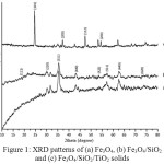 |
Figure 1: XRD patterns of (a) Fe3O4, (b) Fe3O4/SiO2 and (c) Fe3O4/SiO2/TiO2 solids
|
Fig. 2 shows TEM image of the produced Fe3O4/SiO2/TiO2 core-shell nanoparticles. The darker Fe3O4 core particles are covered by a bright shell [A1] of SiO2. However, the TiO2 outer shell is not so obvious since it has very similar darkness with the SiO2 inner shell. It is in agreement with the previous[A2] reports14,15,18. The solids show the good[A3] the magneticproperty as it can be drawn well by an external magnetic bar.
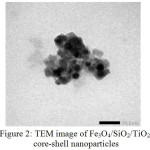 |
Figure 2: TEM image of Fe3O4/SiO2/TiO2 core-shell nanoparticles |
Fig. 3 shows the separation of the product by the use of the magnetic bar[A1] . It shows that the Fe3O4/SiO2/TiO2 core-shell nanoparticles suspension is attracted to the magnetic bar and it leaves the filtrate clear after 5 min of contact. The magnetic material is attracted by the magnetic bar very well. No remaining solid is seen in the bottom of the container, which indicates that the prepared material has good intrinsic magnetic properties.
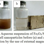 |
Figure 3: Aqueous suspension of Fe3O4/SiO2/TiO2 core-shell nanoparticles before (a) and after (b) separation by the use of external magnetic bar Click here to View figure |
Further, we tested the material by Vibrating Sample Magnetometer (VSM) to determine the magnetization of the solids after they were perturbed by external magnetic field. The application of the external magnetic field results in the hysteresis curve between a given magnetic field strength (H) and the magnetic moment of the sample (M) (Fig. 4). The results show that there is a change in the magnetic properties of Fe3O4 after coating with SiO2 and TiO2. The change in magnetic properties was confirmed by a decline[A1] in the value of the saturation field (Ms) as a result of coating with the other two oxides. It is believed that SiO2 coats well the Fe3O4 particles and reduces the magnetization by external magnetic field. The decrease in the value of the saturation field (Ms) of Fe3O4/SiO2/TiO2 core-shell nanoparticles is also observed, as a result of coating the Fe3O4/SiO2 core by TiO2. Table 1 reveals the magnetic parameters of the products.
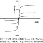 |
Figure 4: VSM curve of (a) Fe3O4,(b) Fe3O4/SiO2 and (c) Fe3O4/SiO2/TiO2 core-shell nanoparticles Click here to View figure |
Table 1: Magnetic property of Fe3O4, Fe3O4/SiO2, and Fe3O4/SiO2/TiO2
|
Material |
Ms (emu g-1) |
Mr (emu g-1) |
Hc (x 10-2 T) |
| Fe3O4Fe3O4/SiO2Fe3O4/SiO2/TiO2 |
76,31 32,58 13,01 |
17,50 10,18 3,45 |
1,90 1,70 1,53 |
Fig.5 shows the effect of pH on the Ag(I) photoreduction. The catalyst performed well at pH 6. At pH lower and higher than 6, the reduced Ag(I) was lower. It has been known that at pH<6, the TiO2surface is mostly in the form of TiOH2+. At pH 2-6, there is charge repulsion between TiOH2+ and Ag+, which both have a positive charge[A1] . It causes the interactionbetween TiO2 with Ag(I) ions to decrease, and thephotoreduction reaction becomes less effective. The more alkaline the solution, the less TiOH2+ species forms butthe more TiOH species forms. Consequently, the electrostatic repulsion between TiO2 and Ag(I) ionsdecreases, leading to the more effective photoreduction.
The reaction can be speculated as follows. After absorbing UV light with appropriate energy, the TiO2 releases electrons (e–) and form holes (h+). The electrons function as a reducing agent for Ag(I) ions. The ensuing reduction process takes place when Ag(I) ions react with electrons generated from water photolysis as well as TiO2 photocatalysis reactions of the Fe3O4/SiO2/TiO2 core-shell nanoparticles. The reactions are as follows:
H2O + hʋ → H+ + •OH + e–
>TiOH + hʋ → >TiOH (h+ + e–)
Ag+ + e– → Ag(s)
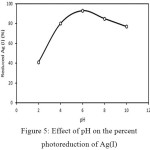 |
Figure 5: Effect of pH on the percent photoreduction of Ag(I) Click here to View figure |
Meanwhile, the decrease in photoreduction is observed at pH range [A1] of 8-10. It is probably due to the formation of silver oxides such as Ag2O, Ag2O2, and Ag2O3 at the base system as shown in the Pourbaix diagram19. The presence of these silver oxides caused the increase of solution turbidity. The particles may cause UV light to scatter, which leads to the decline the photoreductioneffectivity[A2] . Fig. 5 shows that in the alkaline solution, the formation of Ag2O, Ag2O2, and Ag2O3 compounds becomes obvious. In addition, the formation of silver oxide compounds reduces the electrostatic interaction between TiO2 and Ag(I) ions, resulting in the reduction of the [A3] effectiveness of photoreduction reaction.
At pH 6, the TiO2 surface has mostly in the form of TiOH. The absence of Ag(I) and TiOH electrostatic repulsion gives an increase in the photoreduction conversion. Based on the Pourbaix diagram19, at pH 6 silver oxide compound has not been formed, so the UV light is not blocked and easily to reach the TiO2 surface, leading to better photoreduction reaction.
![Figure 6: Effect of loading of Fe3O4/SiO2/TiO2 core-shell photocatalyst on the photoreduction[A1] of Ag(I)](http://www.orientjchem.org/wp-content/uploads/2017/07/Vol33No4_Fe3_Eko_fig6-150x150.jpg) |
Figure 6: Effect of loading of Fe3O4/SiO2/TiO2 core-shell photocatalyst on the photoreduction[A1] of Ag(I) |
To study the effect of photocatalyst load on the photocatalytic reaction, a weight series of 5, 10, 15, 25, 35, and 60 mg were applied. The solution of 25 mL of Ag (I) ions12.5 ppm[A1] was applied at pH 6 with airradiation[A2] time of 2 hours[A3] . The results of the influence of the mass of Fe3O4/SiO2/TiO2[A4] on the photoreduction of Ag(I) is shown in Figure 6.
Fig. 6 shows that the catalyst loading affects photoreduction of Ag(I). The larger photocatalyst loading was used, the more Ag(I) being reduced. The increase in catalyst loading causes the increase in the number of generated electrons. The electrons eventually reduced Ag(I) ions to Ag (0). However, when more photocatalyst was added into[A5] the suspension, it caused the increase of the solution turbidity. The photocatalyst suspension blocked UV beams to enter the reaction mixture. As a result, it reduced the number of electrons generated by the photocatalyst, lowering the photoreduction reaction outcome. A large amount of photocatalysts used does not [A6] necessarily give a high conversion. The best result was obtained with the catalyst[A7] loading of 25 mg. In the ensuing trials, the mass of catalyst loading was predetermined at 25 mg.
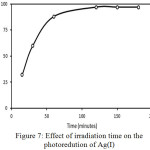 |
Figure 7: Effect of irradiation time on the photoredution of Ag(I) |
Fig. 7 displays the effect of irradiation time on the photoreduction of Ag(I) [A1] ions. In the early time, the reduced Ag(I) is linearly increased along with the irradiation time. As expected, long irradiation time generates more electrons [A2] and causes more Ag(I) to be reduce[A3] d. After 120 minutes, no increase in the reduced Ag(I) was observed. The Ag (0) solid was attached to the surface of the photocatalyst and may hinder contact between the TiO2 and Ag (I) ions which has not been reduced and blocking the absorption of light by the photocatalyst. It shows that the [A4] optimum time for the photoreduction is 2 h. When the time is extended, the amount of reduced Ag(I) is relatively constant.
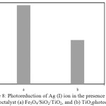 |
Figure 8: Photoreduction of Ag (I) ion in the presence of photoctalyst (a) Fe3O4/SiO2/TiO2, and (b) TiO2photocatalyst |
Photocatalytic activity test under UV illumination of the Fe3O4/SiO2/TiO2 core-shell nanoparticles for Ag(I) ions reduction was performed and compared with that [A1] of the native TiO2. The result is presented in Fig. 8. It shows that the photocatalytic activity of the Fe3O4/SiO2/TiO2 core-shell nanoparticles is much better than that of unmodified TiO2. When exposed to the photon energy of UV light, emission of electrons from the valence band to the conduction band of the photocatalyst occurs. The produced electrons are captured by Ag(I) ions to reduce to Ag(0). As shown in Fig. 6, the Fe3O4/SiO2/TiO2 core-shell nanoparticles shows better photocatalytic activity than that of TiO2. It may be due to the presence of SiO2 in the solid material. The SiO2 coating enhances the surface area and pore volume of the Fe3O4 core20. There is more TiO2 material bonded and the surface area becomes larger, which will lead to the improvement of the photoreduction activity of Ag(I) ions. In addition, the nanosized TiO2 particles have a larger band-gap with a higher photoreduction[A2] capability, hence the strong reducing potential of the photogenerated electrons has made by the core-shell nanoparticles for reduction reactions14.
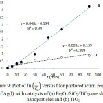 |
Figure 9: Plot of in C/C0 versus t for photoreduction reaction of Ag(I) with catalysts of (a) Fe3O4/SiO2/TiO2core shell nanoparticles and (b) TiO2 |
The reaction kinetics are studied by developing a plot of ln(C/Co) versus t, where Co and C are the concentration of Ag(I) at initial and at time t, respectively. Fig. 9 shows the corresponding plot. The plot suggests that of Fe3O4/SiO2/TiO2 core-shell nanoparticles have larger reaction rate constant than that of unmodified TiO2. The plot is fit to the Langmuir-Hinshelwood kinetics model7,21. The rate of the reaction (v) can be expressed as below.
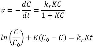
In the latter equation, kr is the rate constant at the equilibrium, and K is the equilibrium constant. If the value of KCe<< 1, the equation can be reduced to v=kr kc . And the Langmuir-Hinshelwood kinetics model can be reduced to the first-order kinetics equation to become the following. A linear plot of ln(C/Co) versus t suggests that the chosen model fit well to the reaction mechanism. Extracted kinetic parameters are presented in Table 2.
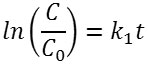
Table 2: Kinetic parameters of photoreduction of silver(I) ) with different catalysts
| Photocatalyst | R2 | k(min-1) | K(mgL-1) |
| Fe3O4/SiO2/TiO2 | 0,9900 | 0,0485 | 5,4174 |
| TiO2 | 0,9093 | 0,0094 | 2,3675 |
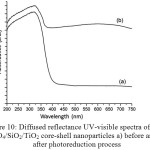 |
Figure 10: Diffused reflectance UV-visible spectra of Fe3O4/SiO2/TiO2 core-shell nanoparticles a) before and b) after photoreduction process |
To confirm the progress[A1] of the photoreduction of Ag(I) to Ag(0), analysis using UV-Visible diffused reflectance (DR-UV) was performed. Fig. 10 displays the DR-UV spectra of Fe3O4/SiO2/TiO2 core-shell before and after photoreduction process. The Fe3O4/SiO2/TiO2 core-shell nanoparticles before photoreduction (Fig. 10a) has a strong peak around 200 to 400 nm. The peak is attributed to the band edge absorption of light by titania in the core-shell nanoparticles. This result suggests that the Fe3O4/SiO2/TiO2 core-shell nanoparticles obtained in this study might be good for photocatalytic reaction under UV irradiation. After photoreduction, however, the Fe3O4/SiO2/TiO2 core-shell nanoparticles give two strong absorption peaks at 318 and 598 nm. A new absorption is observed at the visible range. The absorbance peak at 598 nm is believed to be the absorption peak for Ag(0) of photoreduction product. It suggests that the Ag(0) particles are formed and dispersed in the TiO2 shell of the Fe3O4/SiO2/TiO2 core-shell nanoparticles. It suggests that the photoreductionreaction of Ag(I) to Ag(0) takes place convincingly.
Conclusion
The Fe3O4/SiO2/TiO2 core-shell nanoparticles were prepared via sol-gel process followed by microwave assisted treatment. The Fe3O4/SiO2/TiO2 core-shell nanoparticles show excellent magnetism and higher photocatalytic activity for Ag(I) photoreduction than that of unmodified TiO2. The nanoparticles were able to reduce 97% of aqueous Ag(I) within 120 minutes at the initial concentration of 12.5 mg/L and working pH of 6. The core-shell nanoparticles can be separated from the reaction mixture by simple magnetic separation. This material may find many applications in the treatment organic and inorganic waste.
Acknowledgments
The financial support provided by the Directorate General of Higher Education, Ministry of Research Technology and Higher Education Republic of Indonesia and UniversitasGadjahMada is greatly appreciated.
References
- Ratte, H.T., Environ. Toxicol. Chem., 1999,18(1), 89-108.
CrossRef - Jaskula, M., Jordan J. Earth Environ. Sci.2009, 2(1), 84-95
- Begum, S., Turk. J. Chem. 2003, 27, 609 – 617
- Teng, T.T.; Muthuraman, G.; Mubeena, K.; Sathya, M., J. Membran Sci. Technol. 2013, 3(2), 1-2
- Yonezawa, Y.; Kometani, N.; Sakaue,T.; Yano, A., J. Photochem. Photobiol. A. 2005,171, 1–8
CrossRef - Hidaka, H.; Honjo, H.; Horikoshi, S.; Serpone, N., Sens. Actuators B.2007,123(2), 822-828
CrossRef - Hoffmann, M.R.; Martin, S.T.; Choi, W.; Behremann, D.W., Chem. Rev.1995, 95, 69-95.
CrossRef - Beydoun, D.; Amal, R.; Low, G.; McEvoy, S., J. Phys. Chem. B.2003, 18(104), 4387–4396.
- Lin,Y.; Geng, Z.; Cai, H.; Ma, L.; Chen, J.; Zeng, J.; Pan, N.; Wang, X., Eur. J. Inorg. Chem. 2012, 28, 4439–4444.
CrossRef - Xue, C.; Zhang, Q.; Li, J.; Chou, X.; Zhang, W.; Ye, H.; Cui, Z.; Dobson, P.J., J. Nanomater.2013, 2013, 1-8.
- Ye, M.; Zhang, Q.; Hu, Y.; Ge, J.; Lu, Z.; He, L.; Chen, Z.; Yin, Y., Chem. Eur. J. 2010,16(21), 6243-6450.
CrossRef - Yuan, Q.; Li, N.; Geng, W.; Chi, Y.; Li, X.; Mater. Res. Bull.2012, 47, 2396–2402.
CrossRef - Ruzmanova Y.; Stoller M.; Chianese A., Chem. Eng. Trans. 2013, 32, 2269-2274.
- Kunarti, E.S.; Syoufian, A.; Budi, I.S.; Pradipta, A.R., Asian J. Chem. 2016, 28(6), 1343-1346.
CrossRef - Pang, S. C.; Kho, S.Y.; Chin, S.F., J. Nanomater. 2012, 2012, 1-6.
- Schatz, A.; Hager, M.; Reiser, O., Adv. Funct. Mater.2009, 19, 2109-2115
CrossRef - Abramson, S.; Srithammavanh, L.; Siaugue, J-M.; Horner, O.; Xu, X.; Cabuil, V., J. Nanopart. Res.2009, 11, 459-465.
CrossRef - Roto, R.; Yusran, Y; Kuncaka, A., Appl. Surf. Sci. 2016, 377, 30-36.
CrossRef - Thompson, W.T.; Kaye, M. H.; Bale, C. W.; Pelton, A.D., Pourbaix diagrams for multielement systems. In: Uhlig’s Corrosion Handbook, 3rd Edition, The
Electrochemical Society and Jon Wiley & Sons, New Jersey,2011.
CrossRef - Liu, H.; Jia, Z.; Ji, S.; Zheng, Y.; Li, M.; Yang, H., Catal. Today 2011, 175, 293-298.
CrossRef - Blanco, C.; Granda, M.; Patricia, A.; Asenjo, N.G.; Santamarı, R.; Mene, R., Carbon, 2012, 5, 62–69.

This work is licensed under a Creative Commons Attribution 4.0 International License.
![]()
A New Edition of Web of Science
Journal Impact Factor
2022: 0.5
Five Year: 0.8
Journal is Indexed in

Cabells Whitelist
![]()


