Aluminium Phosphate Supported Copper Phosphate Catalytic Converter to Reduce Nitrous Oxides and Particulate Matter from Engine Emission
S. Sendilvelan1 and K. Bhaskar2
1Dr. MGR. Educational and Research Institute, University, Chennai – 600 095, India.
2Department of Automobile Engineering, Rajalakshmi Engineering College, Chennai- 602 105. India.
Corresponding Author E-mail: sendilvelan.mech@drmgrdu.ac.in
DOI : http://dx.doi.org/10.13005/ojc/330462
To meet the strict emissions regulations, it is required to test and identify highly active and durable catalysts. This paper analyzes the potential of catalytic system in a diesel engine using aluminium-phosphate supported copper phosphate catalytic converter to control nitrous oxide and particulate matter. The particulate matter is reduced by Catalyzed Diesel Particulate Filter (CDPF) and Diesel Oxidation Catalysts (DOC) systems. The soluble organic fractions of diesel particulate are oxidized by DOC system of the newly developed catalyst coated wire meshes, and the un-soluble fractions of particulate matter are filtered by the same wire mesh filter materials. The experimental results from this investigation demonstrate that 40.58% of NOx reduction is achievable, which clearly shows the possibilities of replacing the noble metal catalysts
KEYWORDS:Catalyzed Diesel Particulate Filter; Copper-Aluminium Phosphate Catalyst; Emission Reduction
Download this article as:| Copy the following to cite this article: Sendilvelan S, Bhaskar K. Aluminium Phosphate Supported Copper Phosphate Catalytic Converter to Reduce Nitrous Oxides and Particulate Matter From Engine Emission. Orient J Chem 2017;33(4). |
| Copy the following to cite this URL: Sendilvelan S, Bhaskar K. Aluminium Phosphate Supported Copper Phosphate Catalytic Converter to Reduce Nitrous Oxides and Particulate Matter From Engine Emission. Orient J Chem 2017;33(4). Available from: http://www.orientjchem.org/?p=34961 |
Introduction
The main pollutants from automobile engines include Carbon Monoxide (CO), Oxides of Nitrogen (NOx), Sulphur Dioxide (SO2), unburned hydrocarbons (HC), Suspended Particulate Matter (SPM), Ozone, and Lead 1. Cu-ZSM-5 Zeolite has been proved to be one of the catalysts to detoxify gas emissions 2. Such catalysts however have not been commercialized due to hectic ion exchange of ZSM-5 with Cu, which involves a huge volume of water 3. Another major constraint is the transport of toxic gas emissions into the zeolite pores where the active sites of copper are located and it is very much limited by the micro pores 4,5. The platinum-coated catalyst presently used has the limitations like ammonia being generated on board of the vehicle which requires more space in the vehicle. The platinum being used for coating on ceramic substrates is costly and it is also a scarce commodity. The cost of platinum material is very high and it is more than double the cost of gold. Another problem at present is the unsoluble organic fraction of Particulate Matter (PM) that is unburned carbon particles sticking to filter medium, causing the back pressure to increase over a period of time. So, reducing back pressure to increase the engine performance and reduce the fuel consumption is another aspect to be taken care 6,7. So, there is a scope of finding the alternate catalyst which can replace the noble metals that are presently used to reduce NOx and PM from diesel engine exhaust emissions. However, from the available information, it is learnt that only costly catalytic carrier materials like zeolite or the coating of noble metals like vanadium, platinum, rhodium, which are highly expensive are used as catalysts 8,9. Therefore, in the present experimental investigation, an attempt has been made to investigate the performance of less-cost, easily available metal oxide catalysts to reduce NOx and PM with limited back pressure inside the canister. The newly-developed catalyst is expected to replace the rare-earth, precious, noble metal catalysts that are presently used.
Materials and Methods
Development of Catalyst – Selection of Catalyst
The exhaust canister designed for this study comprises two compartments. The first one is meant for filtration and DOC catalyst. The second compartment is meant for filtration and SCR system. The upstream of the first compartment is filled with steel wire meshes for about one-fourth of canister length. These wire meshes are placed vertically with their surface being parallel to the flow of gas. In this Catalyzed Diesel Particulate Filter (CDPF), sufficient gaps are provided amongst these bundles of wire meshes making the gas to flow crosswise also for better filtration as shown in Figure 1. The wire meshes provide zig-zag path for the gas flow to obtain efficient contact with wire meshes which enhances better filtration as well as better catalytic action in reducing both PM and NOx 10,11,12,13. The important criteria for the selection of catalyst material are higher NOx and PM conversion efficiency, withstanding higher temperatures, avoidance of harmful by-products, cost and its availability14,15,16. Aluminium oxide (alumina) is the base material used for most catalytic converters.
In the present study, aluminium phosphate supported copper phosphate is selected as catalyst. The use of copper phosphate is based on the fact that it can have enhanced sintering resistance and thermal stability. Aluminium phosphate is one of the tough supports to hold the catalytically active ingredients well isolated at high temperatures 17,18 . From the literature, it is found that the phosphoric acid is used as a binding material for binding phosphates, and hence, in the present investigation, the phosphoric acid is used for binding these coppers and Aluminium phosphate powders which gives the desired mechanical properties after binding.
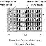 |
Figure 1: A Portion of Sectional Elevation of Canister |
Preparation of Catalyst
Supported metal oxide catalysts are obtained by impregnating active ingredients like copper oxide on a thermally stable inactive support like alumina, magnesia etc. In this study, aluminium phosphate is taken as supporting material and copper phosphate is selected as an active ingredient. The copper phosphate and aluminium phosphate powders are mixed with different proportions as shown in the Table 1, and are named as CAT 1, CAT 2, etc. A measured quantity (10-15% by volume) of ortho-phosphoric acid is added gradually and is thoroughly stirred for better blending. During this process, enormous heat is generated and after a few minutes, it starts hardening. Before it becomes fully hardened, the required shape can be formed by keeping it in between specially prepared dies and gently pressing it. The formed solid catalyst is dried at room temperature for a day. It is found that, during the chemical processing of the powders, they form small granules separated by small gaps, which bring the porosity in the catalyst.
Table 1. Different Proportions of Catalyst
|
Catalyst Type |
Alumino-phosphate % by Volume |
Copper Phosphate % by Volume |
| CAT 1 |
92 |
08 |
| CAT 2 |
84 |
16 |
| CAT 3 |
76 |
24 |
| CAT 4 |
68 |
32 |
| CAT 5 |
60 |
40 |
Experimental Setup
The tests were conducted on a twin-cylinder, 4-stroke, water-cooled, direct injection, constant speed, compression ignition engine is used for this experimental work. The catalytic coated wire meshes and catalytic beads were filled in two compartments. Inside the two compartments, vertical wire mesh bundles were placed first and then the horizontal wire mesh bundles and catalytic beads in alternate layers were assembled. This catalytic converter attachment was connected to the engine exhaust line by a pipe such that the exhaust gas entered the converter axially. The catalytic converter was attached close to the engine exhaust outlet pipe. Proper sealing was provided to avoid exhaust gas leakage.
Results and Discussion
From the experiments conducted, it was found that the oxides of nitrogen increases, with increasing load. When the canister was tested without catalyst, the exhaust gas contained 337 ppm of NOx at no load, and 882 ppm of NOx at full load conditions. The same canister when tested with catalyst coated wire mesh material and catalytic beads, the NOx varied from 247 ppm to 524 ppm at no load and full load conditions respectively i.e. with the newly-developed catalyst, the NOx reduction varied from 26.7% to 40.58%. The increase of NOx was slowed up to 21% load and then the increase was rapid. It was found that, only at higher temperatures, more production of NOx and reduction of NOx at exhaust gas were noticed.
Combined Results of CAT 1 to CAT 5
Figure 2 shows the comparison of the behavior of NOx reduction of all the catalyst proportions of CAT 1 to CAT 5 with that of baseline readings.
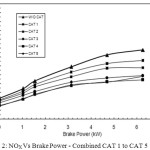 |
Figure 2: NOX Vs Brake Power – Combined CAT 1 to CAT 5 Click here to View figure |
The CAT 4 and CAT 5 show the highest performance in reducing NOx from the engine exhaust. The reason for this is CAT 4 and CAT 5 are prepared with 32% and 40% copper phosphate catalyst material which are responsible for the Selective Catalytic Reduction (SCR) of NOx, breaking them into N2 and O2 and hence more NOx reduction is possible to achieve.
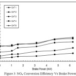 |
Figure 3: NOx Conversion Efficiency Vs Brake Power |
NOx Conversion Efficiency Vs Brake Power
Figure 3 shows that with CAT 1, the NOx conversion efficiency is found as 5.63% at no load. When the load increases to its maximum, the NOx reduction is also increased, but only up to 13.71% (i.e. at full load condition). The net increase in NOx reduction is very low. With CAT 2, CAT 3, and CAT 4 the NOx reduction is gradually increased to 22.78%, 32.88%, 38.43%, respectively. With catalyst 5, the increase in NOx reduction is found as 40.58% at full load. The increase in NOx reduction in CAT 5 is due to the percentage increase of active sites of copper phosphate present in the catalyst. In CAT 1, the active catalyst is only 8%, whereas in CAT 5, it is 40%. The increase in active sites of copper phosphate causes more catalytic action to take place and hence more percentage of NOx reduction is achieved with CAT 5.
Combined Results of CAT 1 to CAT 5
The comparison of performance of PM reduction of all the catalyst proportions with that of baseline readings is shown in Figure 4. In CAT 1, with 8% active catalyst of copper phosphate, PM reduction achieved at full load condition is 9.93 g/kWh. With CAT 2, CAT 3, and CAT 4, the PM reduction is gradually increased compared with without Catalyst. With
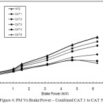 |
Figure 4: PM Vs Brake Power – Combined CAT 1 to CAT 5 |
CAT 5, the PM reduction is found as maximum at 5.9 g/kWh. This increase is due to the fact that with the increased active copper sites in CAT 5 which is having 40% active catalyst of copper phosphate, the oxidation process of SOF of PM taking place inside the canister is more and hence the PM reduction is found maximum with CAT 5.
Comparison of Trap Efficiencies
The PM reduction efficiency i.e. PM trap efficiency versus brake power is shown in Figure 5. The trap efficiency is found as 3.125% only with CAT 1 at no load.
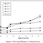 |
Figure 5: PM Trap Efficiency Vs Brake Power |
At full load, this percentage is increased to the maximum of 9.93% only, whereas with CAT 5, the PM reduction efficiency is 18.75% at no load and 56.6% at full load. The reason for this increased percentage of PM reduction is the catalytic action. In CAT 1, the percentage of copper phosphate content is only 8%, whereas in CAT 5 it is 40% and hence more catalytic action causing more oxidation of SOF of PM inside the canister.
Brake Specific Fuel Consumption
In Figure 6, Brake Specific Fuel Consumption (BSFC) is shown against brake power. It is seen that BSFC decreases for all the increasing loads, due to the presence of wire mesh filter materials and catalytic beads inside the canister which give obstruction to the flowing exhaust gas. The higher obstruction offered by the wire meshes and catalytic beads has led to more discharge of fuel for the same work done, leading to higher fuel consumption. Due to increased back pressure, it is found that specific fuel consumption is increased up to 5.62%. This is due to more fuel consumption in the presence of wire mesh filter materials loaded with PM over a period of time and catalytic beads present inside the canister.
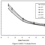 |
Figure 6: BSFC Vs Brake Power |
Trade-off Between NOx and PM
The Figure 7 shows the trade-off relationship between NOx and PM. The presence of oxygen and higher temperature conditions are the two main reasons for NOx production. Since the oxygen concentration in diesel engine exhaust gas is sufficiently high in general, the oxidation largely depends only on temperature. Particulates normally oxidize at temperatures above 550 °C, but higher temperature causes more NOx production. The particulate reduction needs higher temperature whereas rise in temperature leads to more NOx production. That is why, the PM and NOx always have a trade-off relationships. With the newly-developed catalyst, NOx reduction of 40.58% is obtained. With the further improvements on catalytic composition and percentage of the constituents, it is possible to increase the percentage of NOx reduction further.
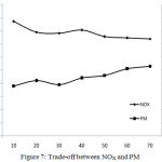 |
Figure 7: Trade-off between NOX and PM
|
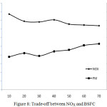 |
Figure 8: Trade-off between NOX and BSFC |
Trade-off Between Nox and BSFC
The trade-off relationship between NOx and BSFC is shown in Figure 8. Simultaneous reduction of NOx in the exhaust emission and fuel consumption is difficult to achieve. This is because NOx adsorption by the catalysts will be more only if the temperature inside the combustion chamber is high and at the same time, due to this phenomenon, fuel consumption will also be more. So, more the percentage of NOx reduction more will be the fuel consumption. More reduction of NOx is achievable with the penalty of more fuel. In the present study, it is found that the specific fuel consumption is increased up to 5.62% for the NOx reduction of 40.58% at full load conditions.
Conclusion
Based on the experiments conducted on direct ignition diesel engine, the following conclusions are drawn:
NOx reduction obtained with non-EGR engine is found as 26.64% at no load and 40.58% at full load and with DOC and CDPF systems, the PM reduction is achieved up to 56.6% at full load condition.
The specially shaped catalytic beads allow the exhaust gas to flow freely without making any obstruction or blocking, and the exhaust gas is free to move in all directions inside the canister.
References
- Reşitoʇlu, I. A.; Altinişik, K.; Keskin, A. Clean Technologies and Environmental Policy. 2014 15–27.
- Konno, M.; Chikahisa, T.; Murayama, T.; Iwamoto, M. SAE Tech. Pap. 1992.
- Beznis, N. V; Weckhuysen, B. M.; Bitter, J. H. Catal. Letters 2010, 138 (1), 14–22.
CrossRef - Jacobs, T.; Chatterjee, S.; Conway, R.; Walker, A.; Kramer, J.; Mueller-Haas, K. In SAE Tech. Pap. SAE International, 2006.
- Sato, S.; Yu-u, Y.; Yahiro, H.; Mizuno, N.; Iwamoto, M. Appl. Catal. 1991, 70 (1), L1–L5.
CrossRef - Komatsu, T.; Nunokawa, M.; Moon, I. S.; Takahara, T.; Namba, S.; Yashima, T. J. Catal. 1994, 148 (2), 427–437.
CrossRef - Xu, L.; McCabe, R. W.; Hammerle, R. H. Appl. Catal. B Environ. 2002, 39 (1), 51–63.
CrossRef - Park, S.-K.; Choo, H.; Kevan, L. Phys. Chem. Chem. Phys. 2001, 3 (15), 3247–3253.
CrossRef - Johansen, K.; Dahl, S.; Mogensen, G.; Pehrson, S.; Schramm, J.; Ivarsson, A. SAE Tech. Pap. SAE International, 2007.
- Ido, T.; Kunieda, M.; Ogyu, K.; Ohno, K. SAE Tech. Pap. SAE International, 2007.
- Sendil Velan, S.; Jeyachandran, K.; Bhaskar, K. SAE Tech. Pap. 2001.
- Chatterjee, S.; Walker, A. P.; Blakeman, P. G. SAE Tech. Pap. 2008.
- Andreassi, L.; Cordiner, S.; Mulone, V. SAE Tech. Pap. SAE International, 2004.
- York, A. P. E.; Watling, T. C.; Ahmadinejad, M.; Bergeal, D.; Phillips, P. R.; Swallow, D. SAE Int. J. Fuels Lubr. 2009, 2, 578–589.
CrossRef - Park, Y.; Lee, B.; Kim, C.; Kim, J.; Nam, S.; Oh, Y.; Park, B. J. Phys. Chem. C 2010, 114 (8), 3688–3692.
CrossRef - Kacimi, M.; Ziyad, M.; Liotta, L. F. Catal. Today 2015, 241, 151–158.
CrossRef - Chung, D. D. L. J. Mater. Sci. 2003, 38 (13), 2785–2791.
CrossRef - Wagh, A. S. ISRN Ceram. 2013, 2013, 20.

This work is licensed under a Creative Commons Attribution 4.0 International License.
About The Author
![]()
A New Edition of Web of Science
Journal Impact Factor
2022: 0.5
Five Year: 0.8
Journal is Indexed in

Cabells Whitelist
![]()


