Optical Effects in the Active Layer of Organic Solar Cells with Embedded Noble Metal Nanoparticles
Supachai Sompech1, Sukhontip Thaomola2 and Thananchai Dasri1,*
1Faculty of Applied Science and Engineering, NongKhai Campus, KhonKaenUniversity, NongKhai 43000, Thailand. 2Faculty of Science and Arts, Chanthaburi Campus, Burapha University, Chanthaburi 22170, Thailand. Corresponding author E-mail: thananchai_dasri@hotmail.com
DOI : http://dx.doi.org/10.13005/ojc/320108
The optical properties of organic solar cells with noble metal nanoparticles such as Ag and Au embedded in the active layer were investigated. The Discrete Dipole Approximation theory was used to analyze the light scattering and absorption efficiencies. The results show that the size, refractive index of medium and amount of the metal nanoparticles are key factors that directly influence the plasmonic enhancements in the devices. These parameters were adjusted for the light scattering and absorption efficiency calculations, which first reveal that as the imaginary part increases more (strongly absorbing medium) both efficiencies decrease slightly and becomes spectrally more broadened. Ag nanoparticle size increases both efficiency peak shifts to the longer wavelength. In addition, the increasing of the nanoparticle size results to the broaden efficiency spectra. When a large amount of particles the scattering and absorption spectral peak of the particles increase, the arrangement in linear chain aligned on the axis which perpendicular to the propagation direction and parallel to the linear polarized light shifts to shorter wavelength. And the higher resonance peak for more particles number is obtained.
KEYWORDS:Optical properties; Metallic nanoparticle; Organic solar cell; Discrete dipole approximation
Download this article as:| Copy the following to cite this article: Sompech S, Thaomola S, Dasri T. Optical Effects in the Active Layer of Organic Solar Cells with Embedded Noble Metal Nanoparticles. Orient J Chem 2016;32(1). |
| Copy the following to cite this URL: Sompech S, Thaomola S, Dasri T. Optical Effects in the Active Layer of Organic Solar Cells with Embedded Noble Metal Nanoparticles. Orient J Chem 2016;32(1). Available from: http://www.orientjchem.org/?p=14112 |
Introduction
The metallic nanoparticles (MNPs) such as Au, Ag and Cu in thin films or nanostructures are potential candidates in many applications such as waveguides1, Organic light-emitting devices (OLEDs)2 and organic solar cells3-9due to their localized surface plasmon resonance (LSPR). LSPRs are well known that certain properties of collective electronic excitations within metal nanostructures that tend to trap optical waves near their interface between the metal and a dielectric medium under excited electromagnetic field10.Organic solar cells (OSCs) have been studied intensively over the past decade for using as the new generation photovoltaic devices due to their attractive properties like less expensive material used in OSCs, much cheaper of the fabrication methods and mechanical flexibility11, 12.A solar cell is defined as OSCs due to the active layer is composed by only organic materials. The basic organic solar cells usually consist of four layers of materials. Starting from the bottom, there is an indium tin oxide (ITO) coated substrate (glass or flexible material) layer, the PEDOT-PSS layer, the active layer and lastly the aluminum top contact4, 7, 8. For the active layer, it constitutes of an organic semiconductor polymer poly(3-hexylthiophene-2, 5 diyl) (P3HT) as an electron donor and [6,6]-phenyl C61 butyric acid methyl ester (PCBM) as an electron acceptor. However, one important problem of OSCs is the limitedlight absorption due to the thin active layer13 limited by the short lifetime of the exciton14 and low carrier mobility of conducting polymers15. To overcome the photon absorption loss and increase the optical path length inside the absorber, one strategy is the utilization of MNPs in OSCs4, 7-9, 16.The MNPs can potentially benefit the photon absorption by utilizing the light trapping mechanism associated localized surface plasmonic resonance which allows MNPs to absorb light, leading to intensification in the light absorption17. Moreover, the incident photons can be scattered over a longer propagation path in the active layer by MNPs18. There exist several strategies to incorporating MNPs in to OSCs, either in front of the solar cell, between the window electrode and the active layer, in the active layer itself, or above the active layer. This strategy has been successfully implemented by many researchers3, 5, 9, 16, 19. Improved optical absorption has been shown theoretically and experimentally with strongly distributed LSPRs around the Au NPs inside the active layer9. In addition, they demonstrate that the small Au NPs in the active layer improve the increase of short-circuit current from 4.16 mA/cm2 to 4.67 mA/cm2. Together with the power conversation, the efficiency (PCE) increases from 1.64% to 2.17%. Moreover, previous work showed that the size dependence of the spherical MNPs, silver (Ag) NPs embedded in absorbing materials of various kinds of absorptivity for light scattering and absorption using the modified Mie theory developed by Kimet al.5. This article demonstrated that the optical absorptions of organic solar cells blended with P3HT (poly (3-hesylthiphene)) and PCBM (phenyl-C61-butyric acid methyl ester) can be enhanced by the Ag NPs embedded in the active layers.
However, due to the influence of metal nanomaterials, optical and electrical properties of OSCs strongly depends on the geometry, material composition size and nanoparticles concentration5, 20. Therefore, this article will theoretically present the effect of LSPR introduced by MNPs on the optical properties of OSCs particularly in the active layer by using Discrete Dipole Approximation (DDA).The study will adjust the geometry and concentration of MNPs for demonstrating the influence of them to optical property. This study will contribute to better understanding the uses of MNPS for enhancing OSCs performances.
Experimental
Computational details
The absorption and scattering efficiencies of the MNPs, Au and Ag nanoparticles, are simulated based on the DDA theory21. This theory, the object in arbitrary shape is replaced with an assembly of N point dipoles in which the polarizability and positions are specified as αi and ri, respectively. The polarization induced in P each particle in the presence of an applied field is then described by:
![]()
Where Eloc is the sum of the incident field and the contribution from all other N-1 dipoles. When this polarization is obtained, the absorption, scattering and extinction cross sections of light can be calculated as follows:
Equations (1) and (2), ‘*’ symbol stands for the conjugate of a complex variable, is the wave number and is the amplitude of incident electric field.And scattering, absorption and extinction efficiencies can be calculated by
![]()
respectively. R is radius of spherical nanoparticle. The only requirement is that the distance between dipoles in the array should be small compared to any structure dimensions of the target as follow:
Where is the volume of the target. The dielectric constants for Ag and Au were taken from the data in Ref. Johnson et al.22. The real refractive index (n) of the absorbing medium for the calculations was 1.7, which is close to that of most organic semiconductors in the visible range. The imaginary refractive index (k) of the host medium was adjusted in order to study the effect of the medium absorptivity.In addition, the influences of the MNPs size and number of nanoparticles on LSPR were also studied.
Results and Discussion
First, thediameter of the Au and Ag spherical nanoparticles of 20 nm6embedded in a medium of various imaginary refractive index (k) from 0 to 0.5 were calculated. The scattering and absorption efficiencies spectra of Au nanoparticle are shown in Figs. 1a and 1b, respectively. These figures show that as the imaginary refractive index increases, k = 0, 0.1, 0.2 and 0.5, the maximum both scattering and absorption efficiencies spectra decreases slightly, clearly shown in Figs. 1c and 1d, and become spectrally more broadened. From the figures the maximum scattering and absorption efficiencies of Au nanoparticle in the non-absorbing medium are 0.009 and 1.97, respectively. The peak positions of enhancement spectra appear around 558 nm. Similar for the scattering and absorption efficiencies spectra of Ag nanoparticle, the calculated results are shown in Fig. 2. Similar to the Au spectra, by increasing the imaginary refractive index more, the maximum both scattering and absorption efficiencies spectra decrease slightly, clearly shown in Figs. 2c and 2d, and also become spectrally more broadened. However, by comparing the Au nanoparticles spectra, interestingly first both efficiencies of Ag nanoparticle are higher than the efficiencies that given by the Au nanoparticle. For example at non-absorbing materials (k=0), absorption efficiency of Ag nanoparticle is 17.5 but Au nanoparticle gives 1.97 which less than approximate 9 times. Second, the efficiencies of Ag nanoparticle decrease abruptly than the efficiencies of Au nanoparticle, especially, as the imaginary refractive index changes from 0 to 0.1. For example for the absorption efficiency, the efficiencies of Ag nanoparticle decrease abruptly from 17.5 to 5.0 while decrease slightly from 1.97 to 1.47. Because the Ag nanoparticle provides a strong scattering and absorption efficiencies, clearly shown in Fig. 2, therefore the only Ag nanoparticle spectra later will be presented. In Fig. 3 shows the dependence of nanoparticle size on scattering and absorption efficiencies of Ag nanoparticles. Figs. 3a and 3b show that as the nanoparticles size increases both efficiency peak shifts to the longer wavelength. In addition, as the nanoparticles size increases more the efficiencies spectra become more broaden, clearly for the diameter of 50 nm. Figs. 3c and 3d show the scattering and absorption efficiencies peak as function of nanoparticle size with various imaginary refractive index k at the wavelength of 434 nm. Fig.4shows scattering and absorption efficiencies for Ag nanoparticles of 20 nm in diameters withvariation of the number of particle and imaginary refractive index are fixed with k=0. The particles are arranged in linear chain aligned on the axis which is perpendicular to the propagation direction and parallel to the linear polarized light. The results reveal that as the particle increases the obtained absorption spectra increase. Moreover, the resonance peak of higher number particle sample shifts to shorter wavelength. For example the resonance peaks of 3, 4 and 5 particles shift to 404, 394 and 386 nm, respectively.
It is clearly that in the spectral range of 350-600 nm, noble metal (e.g. Au and Ag) nanoparticles are embedded in the active or buffer layer of the OSCs exhibit LSPR that couple strongly to the incident light (Figs. 1-3). The previous research works6, 23, 24 reported that the addition of MNPs into buffer layer of the solar cell increased the power conversion efficiency (PCE) as compared to the device constructed without the addition of MNPs. For example in the experimental result, reported by Wuet al.24 show that the photocurrent within the wavelength range from 450-650 nm increased significantly after incorporation the MNPs. This wavelength regime matches with the absorption range of MNPs. This indicates that LSPR effects indeed improve the photocurrent. Moreover, the LSPR effects on OSCs results to the enhancement in the maximum exciton generation rate, Gmax , which is a measure of the maximum number of photons absorbed. The Gmax is proportional to the photocurrent density, Jpk , as follows24:
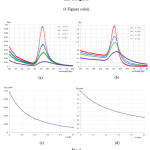 |
Figure 1: Scattering efficiency (a) and absorption efficiency (b) for Au (gold) nanoparticles of 20 nm diameters with varying the imaginary refractive index, (c) and (d) are scattering and absorption efficiencies peaks as function of the imaginary refractive index Click here to View figure |
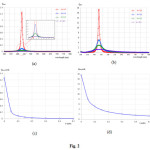 |
Figure 2: Scattering efficiency (a) and absorption efficiency (b) for Ag (silver) nanoparticles of 20 nm diameters with varying the imaginary refractive index, (c) and (d) are scattering and absorption efficiencies peaks as function of the imaginary refractive index Click here to View figure |
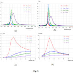 |
Figure 3: Scattering efficiency (a) and absorption efficiency (b) for Ag nanoparticles with varying diameters and fixing imaginary refractive index k=0, (c) and (d) are maximum peak of scattering and absorption efficienciesas function of nanoparticle diameters at the wavelength of 434 nm and imaginary refractive index of the medium Click here to View figure |
![]()
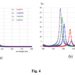 |
Figure 4: Scattering efficiency (a) and absorption efficiency (b) for Ag nanoparticles of 20 nm diameters withvarying the number particle that arranged in linear chain, the imaginary refractive index is fixed with k= 0 Click here to View figure |
Conclusion
The absorption and scattering efficiencies of the MNPs in an absorbing medium with varying their size, medium refractive index and the number of particle were studied using the DDA method. The results found that theincorporating of MNPs in the buffer layer of OSCsshowsstrongly LSPR induced. Moreover, the results revealed that the resonance peak of LSPR depends strongly on the size, the dielectric environment and number of the MNPs.Thus, the basic results of this study might be used for basic fabricating the more performance OSCs.
Acknowledgments
The authors are grateful to the Faculty of Applied Science and Engineering, NongKhai Campus, KhonKaen University for all facilities supported.
References
- Hayashi, S.; Okamoto, T. J. Phys. D: Appl. Phys.2012, 45, 1-24.
- Tang, M.; Zhu, W.; Sun, L.; Yu, J.; Qian, B.; Xiao, T.Synth. Met.2015, 199, 69-73.
CrossRef - Cheng, C.-E.; Pei, Z.; Hsu, C.-C.; Chang, C.-S.;Chien, F. S.-S. Sol. Energy Mater. Sol. Cells, 2014, 121, 80-84.
CrossRef - Kalfagiannis, N.; Karagiannidis, P. G.; Pitsalidis, C.;Panagiotopoulos, N. T.; Gravalidis, C.; Kassavetis, K.; Patsalas, P.;Logothetidis, S. Sol. Energy Mater. Sol.Cells, 2012,104, 165-174.
CrossRef - Kim, C.-H.; Cha, S.-H.; Kim, S. C.; Song, M.; Lee, J.; Shin, W. S.; Moon, S.J.; Bahng, J. H.; Kotov, N. A.; Jin, S.-H. ACS Nano,2011, 5, 3319-3325.
CrossRef - Kozanoglu, D.; Apaydin, D. H.; Cirpan, A.;Esenturk, E. N. Org. Electron. 2013, 14, 1720-1727.
CrossRef - Liu, F.; Xie, W.; Xu, Q.; Liu, Y.; Cui, K.; Feng, X.; Zhang, W.; Huang, Y.IEEE Photonics J.2013, 5, 8400509.
CrossRef - Notarianni, M.; Vernon, K.; Chou, A.; Aljada, M.; Liu, J.; Motta, N. Sol. Energy,2014,106, 23-37.
CrossRef - Wang, C.C.D.; Choy, W.C.H.; Duan, C.;Fung, D.D.S.; Sha, W.E.I.;Xie, F.X.; Huang, F.; Cao, Y. J. Mater. Chem.2012,22, 1206-1211.
CrossRef - Barnes, W.L.; Dereux, A.; Ebbesen, T.W.Nature, 2003,424, 824-830.
CrossRef - Kalowekamo, J.; Baker, E. Sol. Energy, 2009, 83, 1224-1231.
CrossRef - Powell, C.; Bender, T.; Lawryshyn, Y. Sol. Energy, 2009, 83, 1977-1984.
CrossRef - Namkoong, G.; Kong, J.; Samson, M.; Hwang, I.-W.; Lee, K. Org. Electron.2013, 14,74-79.
CrossRef - Theander, M.; Yartsev, A.;Zigmantas, D.; Sundström, V.; Mammo, W.;Andersson, M.R.;Inganäs, O. Phys. Rev. B: Condens. Matter, 2000, 61, 12957-12963.
CrossRef - Street, R.A.; Schoendorf, M.; Roy, A.; Lee, J.H. Phys. Rev. B: Condens. Matter, 2010, 81, 2053071-20530712.
CrossRef - Chen, B.; Zhang, W.; Zhou, X.; Huang, X.; Zhao, X.; Wang, X.; Liu, M.;Lu, Y.; Yang, S. Nano Energy, 2012, 2, 906-915.
CrossRef - Ma, W.; Yang, C.; Gong, X.; Lee, K.;Heeger, A. J. Adv. Funct. Mater.2005, 15, 1617-1622.
CrossRef - Akimov, Y.A.; Koh, W.S.; Sian, S.Y.;Ren, S. Appl. Phys. Lett.2010, 96, 073111.
CrossRef - Kim, I.; Lee, K.-S.; Lee, T.-S.; Jung, D.S.; Lee, W.-S.; Kim, W.M.;Lee, K.-S. Synth. Met.2015,199, 174-178.
CrossRef - Choy, W.C.H. Chem. Commun.2014,50, 11984-11993.
CrossRef - Purcell, E.M.; Pennypacker, C.R. Astrophys J.1973,186, 705-714.
CrossRef - Johnson, P.B.; Christy, R.W. Phys. Rev. B: Condens. Matter. 1972, 6, 4370-4379.
CrossRef - Yoon, W.-J.; Jung, K.-Y.; Liu, J.;Duraisamy, T.; Revur, R.; Teixeira, F.L.;Sengupta, S.; Berger, P.R. Sol. Energy Mater. Sol. Cells,2010,94, 128-132.
CrossRef - Wu, J.-L.; Chen, F.-C.; Hsiao, Y.-S.; Chien, F.-C.; Chen, P., Kuo, C.-H.;Huang, M.H.; Hsu, C.-S.ACS Nano, 2011, 5, 959-967.
CrossRef

This work is licensed under a Creative Commons Attribution 4.0 International License.
![]()
A New Edition of Web of Science
Journal Impact Factor
2022: 0.5
Five Year: 0.8
Journal is Indexed in

Cabells Whitelist
![]()


