Control of oxidizing potential of Pb and Pb-Bi coolants
Vladimir Vladimirovich Ulyanov, Valery Alexeyevich Gulevsky, Alexey Nikolayevich Storozhenko and Yury Alexandrovich Teplyakov
JSC “State Scientific Centre of the Russian Federation – Institute for Physics and Power Engineering named after A.I. Leypunsky”
Russia, 249033, Kaluga region, Obninsk, Bondarenko sq., 1.
DOI : http://dx.doi.org/10.13005/ojc/310426
Article Received on :
Article Accepted on :
Article Published : 26 Nov 2015
Analytical and experimental data on formation of oxygen oxidizing potential in heavy liquid metal coolants (Pb and Pb-Bi eutectic) was considered. It was revealed that oxygen could be both dissolved in these coolants and included in various thermodynamically unstable oxide compounds. In case of heavy liquid metal coolant (HLMC) flowing in non-isothermal circuit, these compounds are broken down with oxygen release or formed fixing dissolved oxygen. The amount of oxygen, which is present in HLMC and exhibits its activity with temperature, could be much greater than the value detected by oxygen sensor. That is why HLMC possess internal oxygen reserves inhibiting corrosion in the circuits. Presence of thermodynamically unstable oxide phases in the above coolants, non-isoconcentration distribution of active oxygen, and impossibility to currently obtain the analytical relationship showing dissolved oxygen distribution make it necessary to use at least three oxygen sensors for studying processes of formation of HLMC oxidizing potential. These sensors should be located in the zones of max and min temperatures (tmax, tmin) and in that at t=450-550°С. In order to assure the most accurate estimate it is reasonable to provide additional two or more sensors in the zone at t=450-550°С.
KEYWORDS:lead, eutectic, bismuth; liquid metal coolants; oxygen activity; circuit; oxygen sensor
Download this article as:| Copy the following to cite this article: Ulyanov V. V, Gulevsky V. A, Storozhenko A. N, Teplyakov Y. A. Control of oxidizing potential of Pb and Pb-Bi coolants. Orient J Chem 2015;31(4). |
| Copy the following to cite this URL: Ulyanov V. V, Gulevsky V. A, Storozhenko A. N, Teplyakov Y. A. Control of oxidizing potential of Pb and Pb-Bi coolants. Orient J Chem 2015;31(4). Available from: http://www.orientjchem.org/?p=12750 |
Introduction
Pb and Pb-Bi heavy liquid metal coolants (HLMC) have a wide range of advantages (Gromov et al., 1992, Gromov et al., 1996, Gulevsky et al., 2008). Under reactor conditions, these coolants become only slightly radioactive, and their characteristics meet reactor neutronics requirements. Owing to the reactor system tightness, HLMC do not have any toxic impact on the personnel and inhabitants in the adjacent area. These coolants are explosion-proof, and their saturated vapour pressure is very low at the working temperatures. HLMC thermal capacity is low, hence, they solidify rapidly after having been removed from the reactor together with the components (for instance, in case of repair), this preventing normally occupied area from contamination (Kruglov et al., 2015). In XX century, the above HLMC properties gave occasion for their rather extensive use in the reactor plants of nuclear submarines (Goverdovsky et al., 2014). Design of small size fast reactor with Pb-Bi coolant SVBR-100 is now under development. This design implies creation of the standard module meeting the railway traffic requirements, and the required size NPP could be built up using several modules. Demand for such a reactor, and its application domain are tremendous. This reactor is supposed to be purchased by various countries, companies and businesses (Milinchuk et al., 2013, Rachkov et al., 2014) for the purpose of power supply of communities, as well as water desalination and petroleum processing facilities, etc. Design of BREST fast reactor with lead coolant is to be completed in Russia. Along with SVBR-100, BREST is the forth generation reactor characterized by inherent safety features (Gromov et al., 1992, Gromov et al., 1996, Martynov et al., 2009, Ulyanov et al., 2012).
Besides, various technological systems using HLMC are designed for creation of valuable technological products, namely: hydrogen, synthetic gas, petroleum products, fresh water, water steam, nanostructured and composite materials, etc. (Askhadullin et al., 2012, Kurina et al, 2006). What is more, in some cases, direct-contact heat exchangers (having no heat transfer walls) can be used, in which HLMC is mixed with various treated media (Gulevsky et al., 2008). There are substantial advantages of direct-contact heat exchangers as compared to traditional heat exchanger designs (tube-and-shell, tube-in-tube, etc.): simpler design; absence of heat transfer wall, which is subject to corrosion, pollution and thermal fatigue; larger heat transfer area per volume unit and lower hydraulic resistance (Ulyanov et al., 2012, Beznosov et al., 2005).
Use of HLMC requires maintaining of the oxidizing potential of coolant and, hence, thermodynamic activity of oxygen dissolved in the coolant (which is explicitly determined by this potential) within the unvarying range of values (Gromov et al., 1992, Gromov et al., 1996, Gulevsky et al., 2008, Martynov et al., 2009, Askhadullin et al., 2013, Shmatko et al., 2002). Otherwise, HLMC would cause heavy corrosion of structural steel (Ivanov et al., 2013). Besides, HLMC excessive oxidation may occur resulting in slag formation on the basis of HLMC oxides, which may be deposited on the inner surface of the circuit components, thus deteriorating thermal-hydraulic characteristics of the circuit. Maintaining activity of oxygen dissolved in the liquid metal within the required range of values would prevent circuit slagging and eliminate negative effects of HLMC corrosiveness (Zrodnikov et al., 2004). On the one hand, protective oxide coatings are formed on the steel surface, which prevent steel matrix from contacting HLMC and, hence, prevent corrosion, and, on the other hand, the possibility of HLMC oxidation causing oxides and slag formation is eliminated (Askhadullin et al., 2011).
In order to meet the above condition of assuring safe reactor operation, continuous control of concentration of oxygen dissolved in HLMC or its thermodynamic activity is required.
Models of dissolved oxygen distribution in circuit
Relationship of basic parameters wich characterizes oxygen content is as follows (Gulevsky et al., 2008, Subbotin et al., 1970, Martynov et al., 2009):
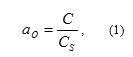
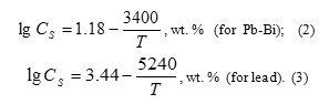
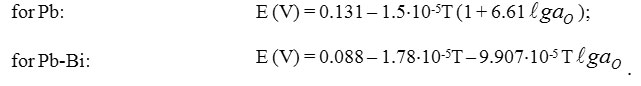
where: α0 – oxygen thermodynamic activity; C – concentration of oxygen dissolved in HLMC; Cs– HLMC oxygen saturation concentration determined as a function of temperature and described by the following relationships (Blokhin et al., 1999):
Oxygen thermodynamic activity in HLMC is the most important parameter of coolant. This determines to a large extent properties of the coolant itself (its corrosiveness with respect to the structural steel, and direction and the rate of the basic oxidation-reduction processes in the circuit) (Gromov et al., 1996, . Subbotin, et al., 1970, Blokhin et al., 1999, Martynov et al., 2009, Askhadullin et al., 2013).
Also, at the moment, а0 is practically the only one parameter out of those determining physical and chemical state of the coolant, which can be setup and continuously controlled using HLMC technology methods in the stages of creation, operation and maintenance of the circuit. The above considerations show the key role of а0 parameter in reactor operation, as well as in experimental and analytical studies.
To date, an opinion predominates that isoconcentration distribution of impurities takes place in HLMC flow circuits (Gulevsky et al., 2008). This view of the coolant impurities condition is demonstrated by the following evidences:
- use of one oxygen sensor for corrosion tests and experimental studies on mass transfer in non-isothermal HLMC circuits;
- use of mass transfer models (presented below) in non-isothermal HLMC circuits for determining temperature range of their safe operation with preset oxygen concentration (activity) value.
The first model (see Figure 1) is α0– C- T diagram for Pb circuit. Line corresponds to ega0 min corresponds to thermodynamic activity of oxygen in oxygen saturated coolant. Line corresponds to the equilibrium of Pb and solid phase of the iron oxide, which is the basis of protective coatings on the steel. In the diagram, presented are the isoconcentration lines of oxygen dissolved in Pb, as well as tmin and tmax lines corresponding to min and max working temperatures in the circuit. The appropriate range of oxygen concentration values is pictorially determined. Oxygen isoconcentration lines passing through tmax and ega0 min lines cross point and through tmin and ega0 = 0 lines cross point present min and max values of appropriate oxygen concentration range.
Diagram area enclosed by tmin and tmax lines and isoconcentration lines drawn from tmax point to ega0 min line and from tmin point to ega0 = 0 line is an area of appropriate oxygen activity in the coolant within the working temperature range of the circuit. Under these conditions, dissociation of protective oxide coatings at the temperatures within tmax and deposition of PbO solid phase at the temperatures equal to tmin and higher are prevented.
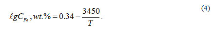
The second model (see Figure 2) being an evolution of the first model is a0 -C- CFe _ T diagram. This was constructed by adding lines of isoconcentration of iron balanced with dissolved oxygen to a0 – C- T diagram. This made it possible for the model 1 (indicating mainly oxygen impurity mass transfer in HLMC) to indicate also iron impurity mass transfer. Iron isoconcentration lines were determined taking into account its maximum solubility as a function of temperature (Weeks et al., 1969):
In model 2, appropriate oxygen concentration is determined by the interval clipped on tmax isothermal curve by the iron and oxygen isoconcentration lines radiating from the cross points of tmin isothermal curve with, respectively, ega0 min and ega0 = 0 lines.
Maintaining oxygen concentration value in the coolant determined in such a way (taking into account the assumption of isoconcentration pattern of impurities distribution in HLMC) prevents severe corrosion of structural materials, as well as crystallization of not only oxygen but also of iron in the cold sections of the circuit. In the second model, area of the appropriate oxygen activity (concentration) is smaller than that in model 1, but it is obvious that model 2 gives more adequate picture of mass transfer processes in the real HLMC circuits.
Understanding of mass transfer within the framework of the above models implies the possibility to provide monitoring and forecasting of thermodynamic conditions and to study oxidation-reduction process rates in the circuit using one oxygen sensor installed in the coolant in any point of the circuit (at the temperature assuring sensor reliable operation).
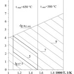 |
Figure 1: Model 1 Click here to View figure |
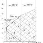 |
Figure 2: Model 2 Click here to View figure |
The common drawback of the models is that they do not take into account interactions of various impurities present in HLMC. However, the probability of this interaction is evident.
Let us consider, as an example, interaction of impurities of oxygen (produced as a result of PbO dissolving) and iron (appearing because of Fe diffusion from the steel surface through protective oxide coating) in liquid lead:
with equilibrium constant:
In case of protective oxide coating available on the structural steel of the circuit (i.e. solid phase Fe3O4) it can be assumed that aFe3O4 = 1 and relationship of equilibrium constant of reaction will be as follows:
Knowing thermodynamic properties of Fe3O4 and PbO, and solubility of iron and oxygen in lead, it is possible to determine specific dissolved iron concentration for each oxygen concentration value (under thermodynamic equilibrium conditions).
Bismuth saturated up to the level of Bi2O3 is used as the reference electrode in oxygen sensors in HLMC (Blokhin et al., 1999, Martynov et al., 2009) So, the relationship for the line of iron isoconcentration in lead can be presented as follows:
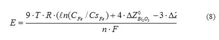
where Т – lead temperature, К; СFe – concentration of iron dissolved in lead, wt.%; СsFe – iron saturation concentration in lead, wt.%; ΔZ0 – Gibbs thermodynamic potentials under standard conditions, J/mole; R = 8.314 J/(К×mole) – universal constant; n = 24 – number of electron moles flowing through electric circuit of the sensor; F = 96485 C/mole – Faraday constant.
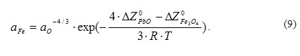
Let us consider in general terms the b
ehavior of oxygen-iron-lead system under non-isothermal circuit conditions. In thermodynamically balanced system, activities of dissolved iron and oxygen are tied by the following relationship:
It is evident that if lead temperature changes from Т1 to Т2, then the initial concentrations of iron and oxygen under new conditions would be equal to the initial equilibrium concentrations at Т1. However, the system is no more thermodynamically balanced because of changes of thermodynamic potentials of iron and lead oxides and change of iron and oxygen saturation solubility. The new thermodynamic equilibrium would be reached after corresponding oxygen exchange in the following reaction:
![]()
in a certain direction depending on the trend of temperature change.
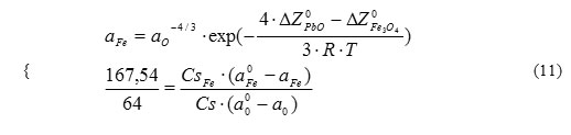
As a result of achievement of the new thermodynamic equilibrium by the system and corresponding oxygen exchange, values of changes of concentrations of iron and oxygen dissolved in lead are, respectively, equal to CsFe.(a0Fe – aFe) and Cs. (a00 -a). Ratio of these two parameters is determined by stoichiometry of reaction (10), and two indeterminates in the new thermodynamic equilibrium state at Т2 (aFe and a0) are determined from two equations set:
![]()
where b and c – constants calculated using reference data as a function of specified initial temperature (Т1), final temperature (Т2), and initial equilibrium oxygen concentration at Т1.
Possible readings of oxygen sensors in Pb calculated by relationship (12) are presented in Figure 3.
The calculation results show that with the coolant deoxidization, sensors readings change from oxygen isoconcentration lines to those practically parallel to the
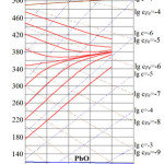 |
Figure 3: Calculated readings of oxygen sensors in Pb Click here to View figure |
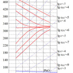 |
Figure 4: Calculated readings of oxygen sensors in Pb-Bi Click here to View figure |
lines of isoconcentration of iron balanced with dissolved oxygen. Decrease of oxygen concentration and increase of iron concentration in lead result in that iron impurities begin to determine the type of oxygen impurity distribution in the deoxidized lead.
Calculations for Pb-Bi alloy have been made in the similar way (taking into account and corresponding temperature dependencies of oxygen and iron solubility in the alloy), and the results are presented in Figure 4. One can see that there is a good qualitative and quantitative agreement between the calculations results presented in Figures 3 and 4.
As it follows from the above considerations, variation of thermodynamic activity (and concentration) of dissolved iron (and, in principle, of any other metal impurity) determines change of thermodynamic activity (and concentration) of oxygen dissolved in HLMC, and vice versa. So, non-isoconcentration impurities distribution in HLMC circuits would almost always take place, although in a varying degree. Additional deviations from isoconcentration distribution could be caused by oxygen sources and sinks present in the circuit (steel components diffusing through protective oxide coatings, steam generator leaks, oxide depositions in the “stagnant” zones, PbO oxide in oxygen activity control device, etc.). With low capacity of sources and sinks and high content of one of the impurities, an assumption can be made of almost isoconcentration distribution of this impurity. This assumption was confirmed by the results of experimental studies carried out at the SSC RF – IPPE (Gulevsky et al., 2008, Gulevsky et al., 2002, Shmatko et al., 2002, Shmatko and Rusanov, 2002). In these studies, oxygen sensors were used, which were based on galvanic concentration cells with ZrO2+Y2O3 solid electrolyte and Bi-Bi2О3 reference electrode. Readings of these sensors vs. Т and а0 are determined by the following relationships (Gulevsky et al., 2008, Gulevsky et al., 2002, Blokhin et al., 1999).
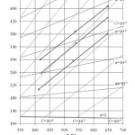 |
Figure 5: Oxygen sensors readings in the course of corrosion tests in Pb Click here to View figure |
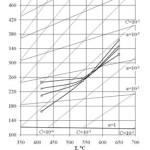 |
Figure 6: Oxygen sensors readings during Pb deoxidization Click here to View figure |
Figure 5 shows oxygen sensor readings put down in the early stage of corrosion tests of structural materials in Pb circuit of CU-1 test facility at the SSC RF – IPPE (Shmatko et al., 2002). In the course of tests, coolant deoxidization took place because of formation of protective oxide coatings on the inner surface of the circuit and ingress of metal impurities (structural steel components) diffusing through the coatings to the coolant. It can be seen that sensors’ readings did not always correspond to the isoconcentration oxygen distribution. These discrepancies, being insignificant with С~10-5wt.%, increased with the decrease of oxygen amount dissolved in the coolant. Oxygen concentration in the “cold” zone was noticeably lower than that in the “hot” zone. Fig. 6 shows sensors readings for lead coolant deoxidization in CU-1 test facility taken after preset oxygen amount was supplied to the coolant (Shmatko and Rusanov, 2002). In this case, oxygen distribution was also significantly different from isoconcentration pattern in spite of high oxygen concentration.
Experimental methods and facilities
Effect of various factors on oxygen distribution in HLMC was studied by the authors using methods of “fast” (Dt ˃ 1°С/s) and “slow” (Dt ~ 100°С/hour) thermal cycling of HLMC. The specific feature of the methods was thermal cycling of the small amount of coolant without forced circulation. Thermal cycling mode made it possible to assure the rates of change of temperature of HLMC with prescribed impurities content close to the average rates of temperature fluctuation in some zones of the real reactor plants in the various stages of their creation and operation, as well as continuous control of thermodynamic activity of oxygen impurity.
Facilities for implementation of HLMC thermal cycling methods are shown in Figures 7 and 8.
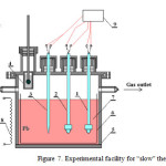 |
Figure 7: Experimental facility for “slow” thermal cycling |
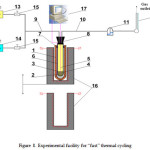 |
Figure 8: Experimental facility for “fast” thermal cycling Click here to View figure |
“Slow” thermal cycling facility (Dt ~ 100°С/hour) consists of the following components: 1-2 – oxygen sensors; 3 – thermocouple in sheath; 4 – movable solid phase (PbO balls) mass exchanger; 5 – reaction vessel; 6 – ceramic bowl; 7 – lead; 8 – variable power electric furnace; 9 – parameters measurement and information collection system. The order of experimental study was as follows:
- loading of pieces of Pb (S-1 brand) or mixture of pieces of Pb (S-1 brand) with Bi (Vi-0 brand) in eutectic proportion to the ceramic bowl of reaction vessel; the loaded mass is 5 kg;
- assembly of facility, its sealing and argon blow, reaction vessel heating up to 500-6000С, and putting oxygen sensors and thermocouple to the liquid metal;
- provision of hydrogen flow through reaction chamber at ~ 4 L/hour rate, purification of liquid metal by hydrogen until 400 mV sensor signal is achieved;
- hydrogen replacement by the inert gas (Ar) and oxidation of liquid metal by periodically putting solid phase (with PbO balls) mass exchanger into it with continuous control of oxygen sensors signals and cycling of reaction chamber temperature at the rate of ~ 100°С/hour.
Facility for “fast” thermal cycling (Dt ˃ 1°С/с) includes the following equipment: 1 – quartz glass retort; 2 – tested liquid Pb; 3 – reaction vessel made of solid electrolyte ceramics ZrO2 + 3% Y2O3; 4 – Bi – Bi2O3 reference electrode; 5 – potential measuring device Mo lead; 6 – thermocouple in Mo sheath also serving as potential measuring device lead; 7 – retort rubber seal; 8 – reaction vessel rubber seal; 9 – potential measuring device Mo lead (capillary); 11 – hydraulic lock; 12 – froth flow meter; 13 – purified Ar vessel; 14 – Н2 vessel; 15 – regulating valves; 16 – vertically movable furnace; 17 – parameters measurement and information collection automatic system.
The order of “fast” thermal cycling experiments is described below. Reaction vessel made of ZrO2 + 3% Y2O3 solid electrolyte ceramics (inner diameter: 8 mm and wall thickness: 0.3 mm) with loaded ~ 6 g of Pb containing 1.10-4 wt.% of Fe is located in quartz retort (inner diameter:10 mm) loaded with Bi and Bi2O3. Using vertically moving furnace, quartz retort was heated up to ~ 4500С. Both Pb and Bi were melted, and Bi – Bi2O3 reference electrode was formed in the retort. Then, facility shown in Fig.8 was assembled and sealed. After that, quartz retort with reaction chamber were used as oxygen sensor. Then reaction chamber was filled with purified argon and its thermal cycling (heating/cooling) with excess amount of О2 in Pb was carried out, oxygen sensor signal being continuously measured. Upon internal purification of the reaction chamber by hydrogen, thermal cycling with excess amount of Fe in Bb was carried out. In the cooling mode, furnace was completely removed from the quartz retort, which was cooled by the air flow.
Results and Discussion
Data obtained on the “slow” thermal cycling facility are presented in Figures 9 and 10.
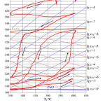 |
Figure 9: Oxygen sensor readings in liquid Pb taken in the course of thermal cycling in static facility (Dt/Dt » 100 °C/hour) |
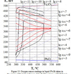 |
Figure 10: Oxygen sensor readings in liquid Pb-Bi taken in the course of thermal cycling in static facility (Dt/Dt » 100 °C/hour) Click here to View figure |
In Figures 9 and 10, presented are the results of а0 measurement during “slow” thermal cycling in ceramic bowls of liquid Pb-Bi and Pb containing about 1×10⁻⁴ wt.% of Fe (i.e. relatively pure in terms of metal impurities).
It can be seen that with С ³ 10-4, sensor readings in all cases correspond approximately to isoconcentration oxygen distribution. In the zone with С £ 10-5, the deviation from isoconcentration oxygen pattern is already observed. Significant deoxidization of liquid metal results in the oxygen distribution lines becoming almost perpendicular to oxygen isoconcentration lines and practically coinciding with the iron isoconcentration lines. In all cases, oxygen distribution discrepancies were detected for temperature increase and decrease. So, patterns of Е, С and values were formed for each thermal cycle.
In the course of the experiments, the abrupt changes of oxygen distribution nature were detected in both cooling and heating modes of the reaction chamber. This was probably caused by disintegration of the oxide combinations (for lead at t £ 5100С)with free oxygen release to lead and formation of the new oxide phases with free oxygen fixation at t > 600 0С.
Results of the “slow” thermal cycling experiments showed the conceptual possibility of formation of complicated patterns of dissolved oxygen distribution significantly different from isoconcentration distribution even in liquid Pb and Pb-Bi relatively pure in terms of metal impurities. The possible causes of these differences are: dissolved oxygen interaction with iron impurity, as well as disintegration and formation of some complex oxide combinations dissolved in the liquid metal or present as colloids.
Results obtained on “fast” thermal recycling facility are presented in Figure11 and 12.
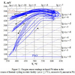 |
Figure 11: Oxygen sensor readings in liquid Pb taken in the course of thermal cycling in static facility (Dt/Dt ˃ 1°C/s, excessive О2 amount in Pb) Click here to View figure |
Experimental studies using “fast” and “slow” thermal cycling methods confirmed the possibility of non-isoconcentration distribution of oxygen dissolved in the coolant over almost the whole temperature range.
Experimental data confirms the statement that in the real HLMC, oxygen is always either dissolved, or as various oxide compounds (which are, apparently, either dissolved in the coolant, or present as colloids). These compounds may either break down thus emitting dissolved oxygen, or they can be formed fixing dissolved oxygen. Their thermodynamic stability is lower than that of Fe3O4, and their oxygen may be involved in the process of the steel surface passivation.
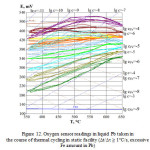 |
Figure 12: Oxygen sensor readings in liquid Pb taken in the course of thermal cycling in static facility (Dt/Dt ˃ 1°C/s, excessive Feamount in Pb) Click here to View figure |
Conclusion
Conclusions based on the results of evaluation of analytical and experimental data on formation of oxidizing potential of oxygen in HLMC are presented below.
- In the real HLMC, oxygen is either dissolved, or present as various oxide compounds (which are, most probably, either dissolved in the coolant, or present as colloids). Determination of their specific form requires additional studies. These compounds may either break down with oxygen emission to the liquid metal, or they can be formed thus fixing dissolved oxygen. Presence of the oxide compounds in HLMC results in that the amount of oxygen exhibiting its activity with temperature fluctuations in HLMC may be much higher than the values indicated by oxygen sensor. Thermodynamic stability of the oxide compounds is lower than that of Fe3O4. And so, their oxygen may be involved in the process of the steel surface passivation. Thus, in the real coolant, there is certain oxygen reserve preventing steel corrosion.
- Currently, it is impossible to present analytical relationship of dissolved oxygen distribution in the real non-isothermal HLMC circuit of reactor plant or facility designed for implementation of the new technologies of solid, liquid and gas media reprocessing. In this view, even rough estimates of the processes of HLMC oxidizing potential formation and mass transfer, and forecasting of the circuit thermodynamics are impossible using one oxygen sensor. At least, three oxygen sensors should be provided in each HLMC heating/cooling section. Such sensor design is under development with the support of the Russian Ministry of Education and Science (Unique Identifier of applied scientific research RFMEFI62514X0002). Oxygen sensors should be located in the zones of tmax, tmin and t=450-550°С temperatures. In order to make more precise estimates, two or more additional sensors should be provided in the zone of t=450-550°С.
- Presence in HLMC of considerable amount of thermodynamically unstable oxide phases, which are not detected by the oxygen sensors, as well as non-isoconcentration distribution of dissolved oxygen require correction of traditional concepts of mass transfer processes in HLMC circuits of reactor plants and facilities for implementation of the new technologies of solid, liquid and gas media reprocessing. It is quite probable that taking into account these corrections, the requirements to preset conditions of coolant circuit operation could become less strict: in particular, the range of permissible (working) C values could be expanded (as compared to those supposed for mass transfer models 1 and 2 presented in section 1). On the other hand, additional requirements may arise concerning conditions of studies on materials corrosion and other mass transfer and mass exchange processes, as well as on coolant technology issues.
References
- Gromov, B.F., Subbotin, V.I., and Toshinsky, G.I. Use of lead-bismuth eutectic and lead as NPP coolants. Atomic Energy, . 1992.,l73 (1), 563-566. DOI: 10.1007/BF00749526.
- Gromov, B.F., and Shmatko, B.A. Physical and chemical properties of liquid lead-bismuth. Proceedings of Higher Education Institutes, Nuclear Power, 1996. 4, 35-41.
- Gulevsky, V.A., Orlov, Y.I., Efanov, A.D., Martynov, P.N., Levchenko, Y.D., and Ulyanov, V.V. Hydrodynamics issues of HLMC technology in loop and pool type reactors. Issues of Atomic Science and Technology, Series: Nuclear Reactors Physics, 2008. 4, 15-33.
- Kruglov, A.B., Kruglov, V.B., Rachkov, V.I., Struchalin, P.G., Kharitonov, V.S., Askhadullin, R.Sh., and Martynov, P.N. Method of measuring of liquid lead thermal conductivity in range 350-1000 °С. Thermal physics of high temperatures, 2015., 53 (4), 596.
- Goverdovsky, A.A., Kalyakin, S.G., and Rachkov, V.I. The alternative strategies of the development of the nuclear power industry in the 21st century. Thermal engineering, 2014. 61 (5), 319-326. DOI: 10.1134/S0040601514050048.
- Milinchuk, V.K., Alekseev, A.V., Merkov, S.M., and Kharchuk, S.E. Using of pyrolysis in liquid metal to perform carbon anode modification. Current issues of humanitarian and natural sciences, 2013. , 9, 23-28.
- Rachkov, V.I., Arnol’dov, M.N., Efanov, A.D., Kalyakin, S.G., Kozlov, F.A., Loginov, N.I., Orlov, Y.I., and Sorokin, A.P Use of liquid metals in nuclear and thermonuclear engineering, and in other innovative technologies. Thermal engineering, . 2014. , 61 (5), 337-347. DOI: 10.1134/S0040601514050085.
- Martynov, P.N., Askhadullin, R.Sh., Simakov, A.A., Lanskikh, V.S., Chernov, M.E., Legkikh, A.Y., and Sadovnichy, R.P.. Automatic system for control of oxygen thermodynamic activity in lead-bismuth coolant. Proceedings of Higher Education Institutes, Nuclear Power, 2009.,3, 176-183.
- Ulyanov, V.V., Gulevsky, V.A., Martynov, P.N., Fomin, A.S., Shelemetev, V.M., Sadovnichy, R.P., and Niyazov, S.A.S. Use of Pb and Pb-Bi coolants in the new technologies of solid, liquid and gaseous media reprocessing. Proceedings of Higher Education Institutes, Nuclear Power, 2012. 4, 102-109.
- Askhadullin, R.Sh., Komlev, O.G., Osipov, A.A., Trevgoda, M.M., and Mileyko, S.T. High temperature composites – materials of nuclear power plants with heavy liquid metal coolants. Composites and nanostructures, 2012. 2, 18-23.
- Kurina, I.S., Askhadullin, R.Sh., Martynov, P.N., Yudintsev, P.A., and Voskresenskaya, V.I. Using of aerogel AlOOH as a component for preparing UO2 tablets and functional and constructional ceramics of nuclear power installations. Issues of atomic science and technology, Series: material science and new materials, 2006. 2 (67), 118-129.
- Beznosov, A.V., Pinaev, S.S., Davydov, D.V., Molodtsov, A.A., Bokova, T.A., Martynov, P.N., and Rachkov , V.I.. Experimental studies of the characteristics of contact heat exchange between lead coolant and the working body. Atomic Energy, 2005.,98 (3), 170-176. DOI: 10.1007/s10512-005-0188-4.
- Askhadullin, R.Sh., Ivanov, K.D., and Martynov, P.N. Studies on the effect of oxygen thermodynamic activity on sorption removal of the impurities from the eutectic Pb (44.5%) – Bi (55.5%). Current issues of humanitarian and natural sciences, 2013. 8, 36-42.
- Shmatko, B.A. , Troyanov, V.M., and Rusanov, A.E. Overall diagnostics of non-isothermal lead test loops by activity measurement methods. Book of abstracts of the Conference “Heat and mass transfer and liquid metal properties” 2002. I,. 27-29. Obninsk, Russia: SSC RF – IPPE.
- Ivanov, K.D., Lavrova, O.V., Niyazov, S.A.S., Salaev, S.V., Rachkov, V.I., and Filippova, M.F. Problems of construction steel passivation in heavy (Pb, Pb-Bi) coolants. Nuclear physics and engineering, 2013. 4 (11-12), 949.
- Zrodnikov, A.V., Efanov, A.D., Orlov, Yu.I., Martynov, P.N., Troyanov, V.M., and Rusanov, A.E.. Heavy liquid metal coolant – lead-bismuth and lead – technology. Atomic Energy, 2004.,97 (2), 534-537 DOI: 10.1023/B:ATEN.0000047678.45415.b6.
- Askhadullin, R.Sh., Ivanov, K.D., Shelemetev, V.M., and Sadovnichy, R.P. Estimation of intensity of construction steel oxidation in first circuit of nuclear power installation with heavy coolants. Proceedings of Higher Education Institutes, Nuclear Power, 2011. 4, 121-128.
- Subbotin, V.I., Ivanovsky, M.N., and Arnol’dov, M.N. (1970). Physical and chemical grounds of use of liquid metal coolants. Moscow: Atomizdat.
- Blokhin, V.A., Budylov, E.G., Velikanovich, R.I., Gorelov, I.N., Deryugin, A.N., Ivleva, J.I., Kozina, M.I.,
- Musikhin, Y.A., Ponimash, I.D., Sorokin, A.D., Shimkevich, A.L., Shmatko, A.B., and Sherbakov, E. G. (1999). Experience gained in creating and operating solid-electrolyte meters of oxygen activity in lead-bismuth coolant. Proceedings of International Conference “HLMC-98” (Vol. 2, pp. 631-635). Obninsk, Russia: SSC RF – IPPE.
- Weeks, J.R., and Romano, A.J. (1969). Liquids Curves and Corrosion of Fe, Ti, and Zn in Liquid Pb-Bi Alloys. Corrosion, 25 (3), 131-136. DOI: http://dx.doi.org/10.5006/0010-9312-25.3.131
- Shmatko, B.A., and Rusanov, A.E. (2002). Structure of oxidizing potential in lead flow when controlling oxygen activity. Book of abstracts of the Conference “Heat and mass transfer and liquid metal properties” (Vol. 1, pp. 176-178). Obninsk, Russia: SSC RF – IPPE.

This work is licensed under a Creative Commons Attribution 4.0 International License.
![]()
A New Edition of Web of Science
Journal Impact Factor
2022: 0.5
Five Year: 0.8
Journal is Indexed in

Cabells Whitelist
![]()


