Simulation of fluid flow and solididification in the funnel type crystalizer of thin slab continuous cast
M.H. Zare1*, A.H. Meysami2, Sh. Mahmoudi3, M. Hajisafari4, M. MazarAtabaki5
1Department of Mechanical Engineering, Yazd Branch, Islamic Azad University, Yazd, Iran. 2Department of Materials Science and Engineering, Golpayegan University of Technology, Golpayegan, Iran.
3epartment of Material Science Engineering, Iran University of Science and Technology, Tehran, Iran.
4Department of Metallurgy & Materials Engineering, Yazd Branch,Islamic Azad University,Yazd, Iran.
5 Research Center for Advanced Manufacturing (RCAM), Department of Mechanical Engineering, Southern Methodist University, 3101 Dyer Street, Dallas, TX 75205, USA.
DOI : http://dx.doi.org/10.13005/ojc/290408
Article Received on :
Article Accepted on :
Article Published : 15 Jan 2014
The present work models the fluid flow and heat transfer with solidification of a steel in the funnel type mold region of a thin slab steel continuous caster.ªª In current modeling a turbulent fluid flow has been supposed and used K-ɛ model in order to anticipate the heat transfer distribution in mold region. To consider the solidification effects on fluid flow and solid crust, the Darci model was applied, also for outlet heat flow measurement a simple method was used. The fluid flowresults indicate a special flow pattern in the caster for a tetra-furcated nozzle. revealed to have two large downward and upward recirculation zones with a classic double-roll and two small vortices generated by the upward flow from the upper ports of the submerged entry nozzle. Heat transfer results indicate that increasing the continuous casting velocity and reducing submergence depth would lead to reduction in the thichness of the solidified shell while decrease the surface freezingFinally achieved the optimum condition related to heat transfer phenomena and surface distribution
KEYWORDS:Modeling; Thin slab; Tetra-furcated nozzle; Heat transfer, Solidification.
Download this article as:| Copy the following to cite this article: Zare M. H, Meysami A. H, Mahmoudi S, Hajisafari M, MazarAtabaki M. Simulation of fluid flow and solididification in the funnel type crystalizer of thin slab continuous cast. Orient J Chem 2013;29(4) |
| Copy the following to cite this URL: Zare M. H, Meysami A. H, Mahmoudi S, Hajisafari M, MazarAtabaki M. Simulation of fluid flow and solididification in the funnel type crystalizer of thin slab continuous cast. Orient J Chem 2013;29(4). Available from: http://www.orientjchem.org/?p=1644 |
Introduction
The process of continuous casting for producing thin slab steels can be performed in an open-end mold and then cooling followed by preheat treatment and the rolling of the products. The thin slab continuous casting process has low energy conservation, less equipment investment, high finished product rate, low production costs, high product quality, more production development potential and many other economic benefits. In this technique, the second step in heat treating of the slabs is removed and costly hot rolling processes are eliminated considering the reduction in the slab thickness. During the casting process, fluid flow jet coming from the nozzle causes high turbulent influencing inclusion/bubble transport and entrapment [1-3], the transport and dissipation of superheat [4], the shape and fluctuations of the top-surface level [5], the entrainment of mold flux from velocity variations across the top surface and surface turbulence. The flow in both the liquid pool is highly turbulent, with Reynolds numbers of about 10,000. Hence, chaotic turbulent structures exist in the mold region even in nominal steady-state casting conditions. This might lead a great effect on the quality of the steels. The easiest way for modeling of the system is to use a refined mesh to resolve turbulent eddies and their movement, but this simulation technique, called direct numerical simulation (DNS), is very expensive and time consuming. Nowadays, another method, large eddy simulation (LES), is replaced for modeling of slab continuous casting.
Liu et al. [6] presented a mathematical model of three-dimensional fluid flow, heat transfer and solidification in thin slab casting based on the enthalpy-porosity approach in a single-phase framework and compared the fluid flow and thermal behaviors in the funnel-type molds. It was shown that the fluid pattern in the liquid pool has two large downward and upward recirculation zones and there are two small vortices generated by the upward flow from the upper ports of the submerged entry nozzle (SEN). The modeling of the solidification and heat transfer in the continuous caster systems might help the better undersatanding of the supercooling and gives enough information on the meniscus solidification to prevent the surface defects. The supercooling in the mold is a dominant solidification factor to define the final microstructure and segregation of the
steel. Increase in the supercooling causes the formation of plannar grains and this would lead to have more internal cracks, so for averting the formation of such a microstructure the fluid pattern should be optimized. The study of the turbulence fluid in the mold in the position of the contact surface between the liquid jet and the mold’s wall is one of the methods to optimize the continuous casting conditions [7]. Mizika [8] and Lait et al. [9] predicted the solid shell formation in the mold from the perspective of the solution of the heat transfer equations for a cast slab moving downward. Huang et al. [10] presented a two dimensional k-ε model model and Seyedin [11] simulated the hat flux in three dimension schem, having both good agreement with the experimental results. Thomas et al. [12] presented a three dimensional model for a quarter of a casting mold with the finite volume method where a commercial code (Fidap) was developed. Zhao et al. [7] showed the heat distribution by LES model in the slab mold and compared the results of the model with experimental measurement of the temperature inside the mold. As the heat transfer in the mold is usually controlled with the space between the solid shell and mold’s wall the heat flux changes with the casting time controls the final properties of the heat distribution [13]. Four main factors (liquid slag, air gap, oscillation marks and air gap) have been mostly foreseen in the models. For example Alizadeh et al. [14] shows a simple method to predict the heat flux concluded that the heat flux has an exponensial relationship between the air gap, distance from the meniscus and water debi.
In the previous work the authors considered the effect of steel/slag interface by the Volume of Fluid (VOF) method and the mathematical solution of the flow field was then solved with appropriate boundary conditions. The results were compared with water model in the Saba steel company (SSC) to verify the analytical and numerical models [15] but the solidification and modeling of the heat transfer was not considered in that work. On the other hand, there are not enough studies on the heat transfer of the thin slab continuous casting with tetra-furcated nozzle. The present paper reports a three-dimensional heat transfer simulation and solidification modeling of a thin slab steel continuous casting system.
Model description
In Fig.2, three dimensional views of the mold and nozzle is shown by presenting funnel geometry of the caster mold (a). As it can be seen, thickness of the mold in the middle is bigger (about 144 mm) and thickness at the corner and bottom of the mold is noticeably smaller (around 62 mm).
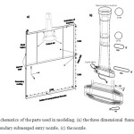 |
Fig.2. Schematics of the parts used in modeling; (a) the three dimensional funnel mold and secondary submerged entry nozzle, (c) the nozzle. Click here to View figure |
In the real model, an additional length of 1200 mm more than the height of the mold is considered for increasing accuracy of the results. The applied grid to solve flow field in the mold region is shown in Fig.3 where the computational domain is divided into 1750000 cells and for more efficiency finer cells has been used in the regions close to the nozzle.
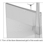 |
Fig.3. View of the three-dimensional grid of the nozzle and mold. Click here to View figure |
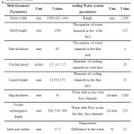 |
Table 1. Process parameters for experiments and computations (mold, nozzle and water circulation system). Click here to View table |
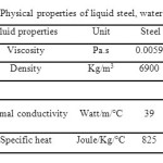 |
Table 2. Physical properties of liquid steel, water and slag. Click here to View table |
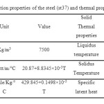 |
Table 3- Solidification properties of the steel (st37) and thermal properties of the solid. Click here to View table |
Mathematical formulation
As the output flow from nozzle port is turbulent, the effect of this turbulent flow is considered using additional equations. In many studies k-ε model has been applied and in the present study this model is adopted to apply the turbulent effects on the flow field. It is assumed that there is three dimensional, steady and incompressible flow for steel in the mold so flow field in three directions can be calculated by the coupled continuity and momentum equations.
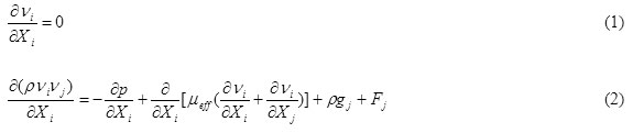
where Vtj is the three-dimensional time-dependent velocity vector, μeff is effective viscosity that can be changed by momentum variations, and it is equal to molecule viscosity and turbulent viscosity.
![]()
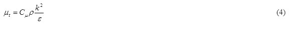
µt can be calculated using k-ε parameters:
k and ε can be predicted by two additional mass transfer equations.
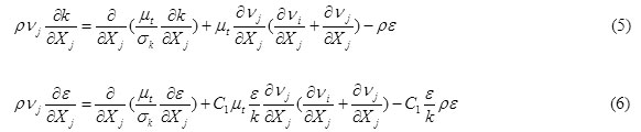
where
Cμ=0.09, Ck=1.00, Cε=1.30, C11=1.44 and C22=1.92.
For the modeling of the heat transfer in the melt and study the solidification, the energy conservation equation can be used where the turbulence, convection and diffusion effect can be foreseen in the equation.
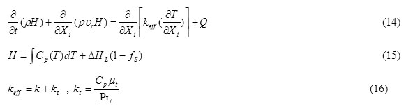
where, T is temperature, ΔHL is the liquid latent heat, Prt the prantle number and kt is the coefficient of the thermal conductivity in the turbulent state. after calculation The solid fraction Darcy source term was applied in momentum equation to considering solidification effect on fluid flow[33] .
Boundary condition
Inlet
Solution of the fluid flow equations started from the middle of the nozzle with the assumption that the nozzle has a circle section (as it can be seen from Fig. 2-a). For this boundary condition one can have :
u=0, ν=0, w=win (8)
where win can be calculated based on the casting velocity by using the following equation:
![]()
For the turbulent parameter one can have:
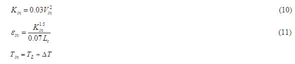
where Lc is the characteristic length and TL is the liquidus temperature of the steel and ΔTis its superheat..
Outlet
In the water molds outlet ports are on the plastic bottom while in the steel casters the mold narrows to the solid end. Hence, boundary conditions were set to be in a constant pressure and all gradients on the outlet ports was assumed to be zero.
Mold walls
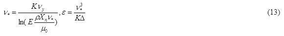
The boundary conditions for the flow on the mold walls can be obtained by using the following equation and assuming that the vertical component and contact velocities are zero.

where k is Von Karman constant, ∆ distance from the wall and ν* is friction velocity that can be calculated by:
The schematic of the mold geometry and boundary condition for energy equation is shown in Fig.14.
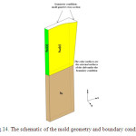 |
Fig.14. The schematic of the mold geometry and boundary condition. Click here to View figure |
For considering the heat transfer between the solid crust and wall of the mold q(z) was defined as the heat flux which was basically a function of distance from meniscus[34], the water debi in cooling channel and the space distance between the mold and solid crust. Therefore, the following equation can be derived

The two dimentional heat transfer models of the liquid steel in the transverse section of the slab, based on the experimental breakout results (the average thickness of the solid crust in the transverse direction was 2 cm and in the thiner layer was 1.8 cm for the speed casting of 3.5 m/min and water cooling debi in table I), lead to a value for α which was 0.95 this coefficient is constant for this casting machine and can use for case study. The other coefficents were presented in Tables 2 and 3. The boundary condition for the convection in secondary cooling is:
qs = hs(T – Tsw)
That hs supposed 550 in this research.
Fluid flow describation mold region
Fig.10 shows three dimensional flow field for the casting when the casting speed was 3.5 m/min and submergence depth was 30 cm, indicating some similarities like four flow recirculation zones with the water model[19]. It should be noted that base on the simulation results about 14-17% of the input melting to nozzle goes out from the upper ports, preventing solidification of the steel on the Top surface especially at the peripheral parts of the nozzle and moving part of the impurities to the free surface.
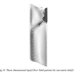 |
Fig.10. Three dimensional liquid flow field pattern for one meter slab[19]. Click here to View figure |
As it can be seen from Fig.11, the flow field pattern in the vertical cross section of the mold alters at the corners and in the section (a), located above of the upper hole. The liquid steel enters upward to the mold and then flows down in peripheral of the nozzle. The top recirculation zone is formed by the steel that reaches the narrow wall of the mold and then flows towards the steel/slag interface. The intensity of the recirculation is a key factor for avoiding instabilities at the interface. In another section (b), located on the same level with lower hole, the high velocity molten steel moves down into the mold. On the other side of this section, upward flow of the upper recirculation zone can be seen. The outlet flow from the lower port of the nozzle then touches the corner walls (c) while it still intends to go down the mold and creates the lower recirculation zone. Finally, the steel flows downwards in section (d) and comes to the mold bottom.
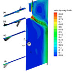 |
Fig.11. Flow field pattern in four vertical cross sections. Click here to View figure |
Flow vectors are drawn in the central plane with assuming that the casting speed is 3.5 and 5.5 m/min in the submergence depth of 40 cm (see Fig.12). As it is shown with increasing casting speed the velocity of the liquid jet increases and consequently the speed of the flow towards the free surface and the mold walls enhances, producing more surface turbulence at the steel/slag interface and as a result increasing the probability of entering slag and impurities. In addition, because of increasing the jets exiting the nozzle ports, the solid shell becomes thinner and the breaks-out occurs outside the mold.
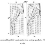 |
Fig.12. Symmetrical liquid flow pattern for two casting speeds (a) 3.5 and (b) 5.5 m/min. Click here to View figure |
One of the main parameters in this process is the submergence depth. With increasing the depth from 30 to 40 cm less flow from the upper nozzle hole moves to the free surface and as a result surface turbulent decreased, reducing the chance of combining the impurities and entering them to the steel (see Fig.13).
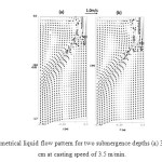 |
Fig.13. Symmetrical liquid flow pattern for two submergence depths (a) 30 and (b) 40 cm at casting speed of 3.5 m/min. Click here to View figure |
The top surface velocity greatly influences the harmful presence of the mold slag. The high velocity of the flow of the top surface can shear slag into the steel pool to form nonmetallic inclusions that causes serious defects. On the other hand, increasing the submergence depth and contact of the fluid from lower nozzle port to the lower part of the solidified shell can cause the breakout. In contrary, at the top surface the flow field is weaker and meniscus is more likely to solidify, giving a chance for the formation of defects like blisters and oscillation mark on the surface of the slabs and rolling products [21-24]. The steel jets traverse the liquid pool to impinge against the narrow faces, splitting into two flows along the narrow face. Upward flow transports superheat and momentum to the top surface. If this flow is too slow or too cold, the meniscus can freeze to form a subsurface hooks and deep oscillation marks. However, excessive velocity and turbulence of this flow can cause surface-level fluctuations that disturb meniscus solidification, entrain inclusions and bubbles. The flow also transports inclusion particles, which can be safely removed into the mold slag or can be entered as defects into the solid steel shell.
Study of the solidification process
As the fluid flow, and heat transfer have interlink relationship in the mold, the turbulence fluid flow increases the heat transfer in the mold pool and controls the path of the heat transfer, superheat dissipation and solidification crust, also) solidification and mushy region can changes the flow patern. The coefficients of heat transfer were measured for the wide and thin parts of the mold and has been drawn in Fig.15. It can be inferred that with moving to the lower part of the mold and with getting closer to the area of the formation of the air gap, the rate of heat transfer reduces and the heat transfer coefficient in the narrow face was higher.
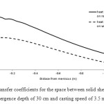 |
Fig.15. The heat transfer coefficients for the space between solid shell and mold for the submergence depth of 30 cm and casting speed of 3.5 m/min. Click here to View figure |
The result of the heat distribution of the liquid in the mold is presented in Fig.16. The section (a) is for the temperature distribution in the symmetry face of the mold and section (b) is the temperature distribution in the external surface of the mold. Initially, the superheat was 40 °C in the entrance section of the mold and then the liquid looses its superheat with moving in the mold pool. The flow from the lower holes hits to the thin wall and forms two lower and upper rings In the center of the mold the liquid temperature is low which was because of low fluid velocity far and super heat dissipation in this region. At the buttom of the mold the distribution of the temperature was more uniform and the melt flow at top surface of mold has enouth super heat (in this submergence depth) for avoiding freezing, in impingment zone the thickness of solidified shell that created in upper part reduce alittle that this reduction can be increase in higher casting velocity.
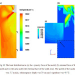 |
Fig.16. The heat distribution in (a) the symetry face of the mold, (b) external face of the mold and (c) the area under the external face of the solid crust. The speed of the casting was 3.5 m/min, submergence depth was 30 cm and superheat was 40 °C. Click here to View figure |
Fig.17. shows the distrbuation of temperature in mushy zone region at cross section of A-A (buttom of the mold) and section B-B (100cm under section A-A) . The uniform distribution of shell thikness in section A-A is indication of the grerat effect of the flow pattern on amount of solidification rate. In wall mold that flow intensity is maximum the solid crust has minmum thikness and in the middle region where is minimum flow intensity the maximum of solid crust is observable.
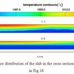 |
Fig.17. The temperature distribution of the slab in the cross section A-A and B-B shown in Fig.16. Click here to View figure |
Fig.18 shows the comparison of a real value obtained from breakout with the predicted profile of solidification at A-A cross section (buttom of the mold) , which displays a completely good agreement between the experimental and numerical results.
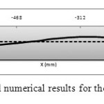 |
Fig.18. The experimental and numerical results for the thickness of the solid crust. Click here to View figure |
The growth of the solid shell in the length of the mold and at narrow face for two casting speeds (3.5 and 5.5 m/min) and submergence depth (30 and 40 cm) were shown in Fig.19.
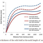 |
Fig.19. The thickness of the solid shell at the mold length of norrow face. Click here to View figure |
As it can be seen increasing the casting speed in every submergence depth causes the reduction in the thickness of the solid shell. In addition, with increasing the submergence depth the thickness of the external solid shell was increased so it can be said that in the higher casting velocity the reduction in the solid shell thickness can be prevented by enhancing the submergence depth. Another point that can be seen from this graph is that the growth of the solid shell can be stop or reduce in the middle part of the mold that associated with the sudden hitting of liquid jet to the solid shell. Generally the effect of casting velocity in shell thickness is higher than submergence depth and with increasing submergence depth the location of shell thickness reduction move to lower location in the mold wall, Fig.20. shows the effects of the submergence depth and casting velocity on the shape of the solid crust in the symmetry face of top mold region . As it is shown, reduction in the casting speed and enhacement in the submergence depth causes the expansion of the mushy zone in the upper part of the mold and close to the narrow face and therefore the probability of surface defect can be increase.
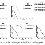 |
Fig.20. The influence of the submergence depth and casting speed on the solid crust. Click here to View figure |
as can see in Fig. 20 –e the solid crust and mushy thickness in the submergence depth of 40 cm and casting speed of 3.5 mm/min is maximum but in this condition the solidified front can not completely be reached to the upper part of the mold for better illustration the 2D section of top surface showed in Fig.21. As it can be seen the lowest amount of solid fraction is in the contact area of outlet jet from upper hole to top mold surface (region (a)), and the highest amount of the solidified liquid is at the corner side of the mold (region c). In the region d also the solidified liquid was locally increased.
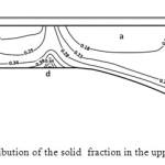 |
Fig.21. The distribution of the solid fraction in the upper part of the mold. Click here to View figure |
Conclusion
In this studythe coupled fluid flow and solidification phenomena are modeled inside the mold region of a thin slab steel continuous casterThe result show that The flow field pattern in the steady condition has two recirculation zones from the lower port and two vorticity from the upper portwith this validated fluid flow profile energy equation solved for prediction of temperature and solid fraction in mold pool .
- Increasing of casting velocity causes thinning the external solid crust, also, increasing of immersing depth causes increase the thikness of external solid crust from mold.
- In order to solve problem of thikness decreasing that occurred due to incrasing of casting velocity, the immersion depth should be increased.
- Increasing of immersion depth causes increasing of pasty region on mold surface specially crossing region of thin and wide sides and middle region of mold surface.
- Based on result that get from simulation of steel/slag interface It is found that higher submergence depths are giving suitable waves in order to prevent any instability at the steel/slag interface. In order to avoid surface turbulence submergence depth should be increased but for having the better solidification condition and particle transport phenomena decreasing the submergence is much more suitable.
According to results in this paper and previous work [19], strongly recommend that the immersion depth not exceed from 40 cm and should be set in range of 30 to 40 cm. In order to avoid from surface turbulence, when the immersion depth is 30 cm, the casting velocity should be not exceed from 4.5 m/min and when the immersion depth is 40 cm also the maximum of casiting velocity set into 5.5 m/min in order to avoid from surface solidification.
Acknowledgements
The authors wish to thank the Saba steel company and Special thanks to Dr. Seyediand Dr. Aboutalebi from Iranian Science & Technology University for their comments on the structure and technical part of the research.
References
- R. C. Sussman, M. Burns, X. Huang, and B.G. Thomas, Inclusion particle behavior in a continuous slab casting mold, 10th Process Technol. Conf. Proc., ISS, Warrendale, PA, 10 (1992), pp. 291-304.
- Y. Ho, C. Chen, and W. Hwang, Analysis of molten steel flow in slab continuous caster mold, Iron Steel Inst. Jpn. Int., 34 (3) (1994), pp. 255-64.
- B. Grimm, P. Andrzejewski, K. Muller, and K.-H. Take, Inclusions in continuously cast steel slabs-numerical model and validation, Steel Res. 70 (10) (1999).
- X. Huang, B.G. Thomas, and F.M. Najjar, Finite-element modeling of turbulent fluid flow and heat transfer in continuous casting, Metall. Trans. B, 23B (1992), pp. 339-56.
- D. Gupta and A. K. Lahiri, Water-modeling study of the surface disturbances in continuous slab caster, Metall. Mater. Trans. B, 25B (1994), pp. 227-33.
- A. Theodorakakos and G. Bergeles, Numerical investigation of the interface in a continuous steel casting mold water model, Metall. Mater. Trans. B, 29B (1998), pp. 1321-27.
- B. G. Thomas, Q. Yuan, S. Sivaramakrishnan, T. Shi, S.P. Vanka, and M.B. Assar, Comparison of four methods to evaluate fluid velocities in a continuous slab casting mold, Iron Steel Inst. Jpn. Int., 41 (10) (2001), pp. 1262-1271.
- G. A. Panaras, A.Theodorakakos, G. Bergeles, Numerical investigation of the free surface in a continuous steel casting mold model, Metallurgical And Materials Transactions B, 29B (1998), pp. 1321-1327.
- A. Theodorakakos, G. Bergeles, Numerical investigation of the interface in a continuous steel casting mold water model, Metallurgical and Materials Transactions B, Vol. 29B (1997), pp. 1321-1327.
- S. H. Seyedein, 3-Dimentional modeling of various slab and thin strip twin-roll casting processes, Ph.D Thesis, McGill University, Canada, (1997).
- D. Gupta, A.K. Lahiri, Cold model study of the surface profile in a continuous slab casting mold: Effect of second phase, Metallurgical and Materials Transactions B, Vol. 27 (1994), pp. 695-697.
- A. Theodorakakos, G. Bergeles, Numerical investigation of the interface in a continuous steel casting mold water model, Metallurgical and Materials Transactions B, 29B (1997), pp. 1321-1327.
- M. B. Goldschmit, S. P. Ferro, A. H. Owen, Modelling of liquid steel flow with free surface, Progress in Computational Fluid Dynamics, 4 (2004), pp. 13-19.
- Q. Yuan, transient study of turbulent flow and particle transport during continuous casting of steel slabs, Ph.D. Thesis (2004), University of Illinois, Urbana-Champaign.
- Q. Yuan, B.G. Thomas, S.P. Vanka, Study of transient flow and particle transport in continuous steel caster molds: part i. fluid flow, Metallurgical and Materials Transactions B, 35B (2004), pp. 703-714.
- J. W. Rottman, Steep standing waves at a fluid interface, Journal of Fluid Mechanics, 124 (1982), pp. 283-306.
- D. Gupta, A.K. Lahiri, A water model study of the flow asymmetry inside a continuous slab casting mold, Metallurgical and Materials Transactions B, Vol. 27 (1994), pp. 757-764.
- H. Liu, C. Yang, H. Zhang, Q. Zhai and Y. Gan, Numerical simulation of fluid flow and thermal characteristics of thin slab in the funnel-type molds of two casters, ISIJ International, 51 (3) (2011), pp. 392-401.
- M. H. Zarea, A. H. Meysami, Sh. Mahmoudi, M. Hajisafari, M. Mazar Atabaki, Simulation of flow field and steel/slag interface in the mold region of a thin slab steel continuous caster with tetra-furcated nozzle, Journal of Manufacturing Processes 15 (2013) 307-317.
- M. Meratian, Modeling of slab continuous casting, A research report, Isfahan science & technology town, 2006.
- B.G. Thomas, Modeling of continuous casting defects related to mold fluid flow 3rdInternat. Congress on Science & Technology of Steelmaking, Charlotte, NC, AIST, pp. 847861, (2005).
- B. G. Thomas, L. Zhang, State of the art in the control of inclusions during steel ingotcasting, Metallurgical and Materials Transactions B, Vol. 37B, pp. 733761, (2006).
- L. Zhang, B. Rietow, B.G. Thomas, K. Eakin, Large inclusions in plaincarbon steel ingots cast by bottom teeming, ISIJ International, Vol. 46, pp. 670-679, (2006).
- J. Sengupta, B.G. Thomas, H.J. Shin, G.G. Lee, S.H. Kim, A new mechanism of hook formation during continuous casting of ultra low carbon steel slabs, Metallurgical and Materials Transactions, Vol. 37A, PP. 1597-1611, (2006).
- B. Zhao, B.G. Thomas, S.P. Vanka, R.J. O’malley, “Transient fluid flow and superheat transport in continuous casting of steel slabs”, Metallurgical And Materials Transactions B, Vol. 36B, pp. 801-823, (2005)
- .A. Mizikar, “Mathematical heat transfer model for solidification of continuously cast steel slabs”, Trans. TMS-AIME, Vol. 239, pp. 1747-1753, (1967)
- J.E. Lait, J.K. Brimacombe, F. Weinberg, F.C. Muttitt, “The liquid pool geometry and cast structure in continuously cast blooms and beam blanks at the algoma steel corporation”, Open Hearth Conf Proc, Warrendale, PA, (Cleveland, OH), Vol. 56, pp. 269-302, (1973)
- X. Huang, B.G. Thomas, F.M. Najjar, “Modeling superheat removal during continuous casting of steel slabs”, Metall. Trans. B, Vol. 23B , PP. 339-356, (1992)
- S. H. Seyedein, “3-Dimentional modeling of various slab and thin strip twin-roll casting processes”, Ph.D Thesis, McGill University, Canada, (1997)
- B.G. Thomas, R. O’Malley, T. Shi, Y. Meng, D. Creech, D. Stone, “Modeling of Casting, Welding and Advanced Solidification Simulation of a Continuous Thin-Slab Caster”, Modeling of Casting, Welding and Advanced Solidification Processes IX, pp. 769-776, (2000)
- B.G. Thomas, “Continuous casting: modeling”, The Encyclopedia of Advanced Materials, Pergamon Elsevier Science Ltd., Oxford, UK, Vol. 2, ( 2001)
- Y. Meng, “Modeling interfacial slag layer phenomena in the shell mold gap in continuous casting of steel”, Ph.D. Thesis, University of Illinois, Urbana-Champaign (2004).
- V.R. Voller, C. Prakash, “A Fixed grid numerical modeling methodology for convection-diffusion mushy region phase change problems”, Int J. Heat Mass Transfer, Vol. 30, pp. 1709-1719, (1987)
- M, Alizadeh, A. J. Jahromi, O. Abouali, “New analytical model for local heat flux density in the mold in continuous casting of steel”, Computational Materials Science, Vol. 44, pp. 807–812, (2008)

This work is licensed under a Creative Commons Attribution 4.0 International License.
![]()
A New Edition of Web of Science
Journal Impact Factor
2022: 0.5
Five Year: 0.8
Journal is Indexed in

Cabells Whitelist
![]()


