Analysis of Effects Resulted from Changing the Buffer Layer Material on Optimization of Cu (In 1-x,Gax) Se2 Thin Filmsolar cell(CIGS) and Simulation of Cell Structure
Nafise Shams1* , Ahmad Afifi2 and Azam Marjani3
1Department of Science and Research branch of Electronic Engineering, Islamic Azad University, Arak (Iran) 2MUT-Department of Electronic Engineering, Tehran (Iran) 3Department of Chemistry, Islamic Azad University, Arak (Iran)
DOI : http://dx.doi.org/0.13005/ojc/290359
Article Received on :
Article Accepted on :
Article Published : 28 Oct 2013
Due tothe present globalunderstandingabout utilization ofrenewable energysources as constantcleanones, PVpowerhas beenthefocused bymanyresearch centers. Research of developmentofPhotovoltaic Energyis generally done in tow fields:reducingcosts andincreasing efficiency. CIGS thin film solar cells are of particular importance among the other types of the same category, due to the flexibility and yields of about 20%.Thispaper examines theperformance ofnanostructuredCIGSsolarcellsare discussed. The impact of changing material in the buffer layer of cell structure on electrical properties and the overall performance is evaluated. The optimized efficiency is also determined using simulation tools.
KEYWORDS:PV;Nano-structured thin filmsolar cellefficiency
Download this article as:| Copy the following to cite this article: Shams N, Afifi A, Marjani A. Analysis of Effects Resulted from Changing the Buffer Layer Material on Optimization of Cu (In 1-x,Gax) Se2 Thin Filmsolar cell(CIGS) and Simulation of Cell Structure. Orient J Chem 2013;29(3). doi : http://dx.doi.org/10.13005/ojc/290359 |
| Copy the following to cite this URL: Shams N, Afifi A, Marjani A. Analysis of Effects Resulted from Changing the Buffer Layer Material on Optimization of Cu (In 1-x,Gax) Se2 Thin Filmsolar cell(CIGS) and Simulation of Cell Structure. Orient J Chem 2013;29(3). Available from: http://www.orientjchem.org/?p=380 |
INTRODUCTION
CIGS1 solar cells based on semiconductor offers many advantages such as flexibility, high efficiency, the ability to change the width of the CIGS strip with Ga composition from 1.04 to 1.68eV to match the solar spectrum and absorption of many photons, compliance CIGS thermal expansion coefficient of the glass substrate made of cheap soda.
In order to create sudden link with a window layer, the carriers’ concentration and the CIGS resistance and its intrinsic composition control and without the use of external impurities can be controlled.
The solar cell performance is very stable and due to extreme changes in temperature and radiation -resistant space, in addition to the availability of land can be used in the air-spaceto supply the energy for satellite1.
This type of solar cell layers, as shown in Fig. 1, usually include: 1 – TCO2 glass substrate coated with a transparent conductive oxide ZnO material 2- Cd S buffer layer with n-type impurities 3- CIGS absorber layer with p-type impurities 4-Mo layer 5- Material Sodaglass substrate2,3.
The first layer is aluminum with zin coxide impurities (ZnO: Al) and Zinc oxide layer (n-ZnO) and as the TCO (Transparent Conductive Oxide), which is to provide the necessary guidance for photons. A substance that is used as the TCO layer must have a large band gap to ensure maximum sunlight absorbency, so that most photons are effectively absorbed. n-CdS layer as a buffer layer used between p-CIGS and TCO layers researches have shown that the cells in the presence of such buffer layer is much better1. This layer consists of CIGS layer to make the p-n junction. CIGS layer. As the absorbent layer with the absorption coefficient of approximately 10cm-1 in the photovoltaic piece is a very crucial layer. Molybdenum layer (metal super alloys) performs as the collector of carriers from CIGS absorbent layer and transfers them to anexternal load. A substance used as a backup connection must have a low resistance barrier, and blocks the majority carriers and the holes. The glass substrate of the solar cell is (Soda)4.
This paper investigates the effect of changing buffer layer materials has been identified and the optimize efficiency has been determined using simulation tools.
Efficiency analysis of solar cells with a common structure
Profile of the layers in the typical solar cell, according to some articles, including reference[2] is as follows:
In Figure (2) the simulatedsolar cell by forming layers in the Silvaco Software and (3) Solar cell efficiency versus wave length curve is drawn.
(According to the following formula, the electrical characteristics of solar cells can be obtained.
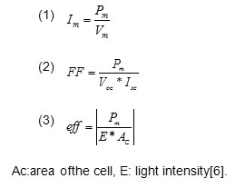
As it’s specified in chart 2, the solar cell efficiency is obtained: 19,70%.
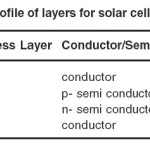 |
Table 1: Profile of layers for solar cell simulation Click here to View table |
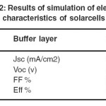 |
Table 2: Results of simulation of electrical characteristics of solarcells Click here to View table |
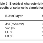 |
Table 3: Electrical characteristics results of solar cells simulation Click here to View table |
Then, the evaluation of efficiency changes is considered.
Simulation of solar cells by changing the buffer layer material
Due to the toxicity of cadmium sulfide(CdS)7 and also to improve the physical structure and efficiency of the solar cell, in this part of the research, changes inefficiency of solar cells has been investigated, by changing the buffer layer
material.
Buffer layer: MgZnO
MgZnO is a flexible Nano Crystal; with a low remix capability and tunable gap of 4.02 ev[8] which can be a great alternative for CdS, if having high efficiency in solar cell. At this stage of the investigation of the buffer layer for GIGS, 0.2 um thick MgZnO Nano crystallineis intended. Figure(4), presents the new yield curve versus wavelength.
According to results from chart 3, solar cell efficiency with ZnMg buffer layer has decreased about 2% in comparison with solar cell efficiency with Cds buffer layer. Due to the fact that efficiency of 17% is an acceptable efficiency in solar cells, as a result it can be a sufficient supplant for Cds in some cases that MgZnO has a better function.
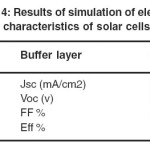 |
Table 4: Results of simulation of electrical characteristics of solar cells Click here to View table |
Buffer layer: ZnMg
ZnMg is also a flexible Nano crystal[9], which can serve as a buffer layer in CIGS solar cells.
At this stage of thei nvestigation the buffer layer GIGS, Nano crystalline ZnMg with 0.2 um thickness.
According to the results from table(4), the efficiency of solar cells with ZnMg buffer layer has declined by about 2% relative to the efficiency of solar cells with Cd Sbuffer layer. Due to the fact that 17% efficiency in solar cell is an acceptable efficiency, as a result it can be a suitable replacement for CdS in some applications with better performance of Zn-Mg layer.
Buffer layer: ZnSe
Zn Se is a II-VI compound semiconductor material that has many applications in optical and electrical equipment. Due to the wide range of optical properties such a slow absorption wavelength and high reflection coefficient for other
wavelengths, it’s used in solar cells. Having a direct band gap of 2.7ev at room temperature Zinc Selenide, is applicable in photo voltaic devices10. At this stage semiconductor ZnSe with 0.2 um thickness is considered as the CIGS buffer layer.
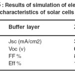 |
Table 5: Results of simulation of electrical characteristics of solar cells Click here to View table |
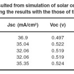 |
Table 6: Characteristics resulted from simulation of solar cells with 4 different buffer layers and the comparing the results with the those of the reference paper[2] Click here to View table |
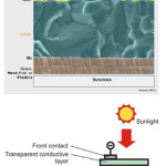 |
Fig. 1: Structure of CIGS solar cells5 Click here to View figure |
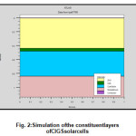 |
Fig. 2: Simulation ofthe constituent layers of CIGS solar cells Click here to View figure |
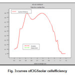 |
Fig. 3: Curves of CIGS solar cell efficiency Click here to View figure |
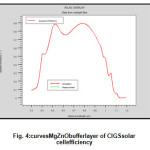 |
Fig. 4: Curves MgZnO buffer layer of CIGS solar cell efficiency Click here to View figure |
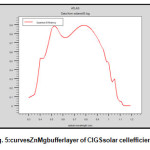 |
Fig. 5: Curves ZnMg buffer layer of CIGS solar cell efficiency Click here to View figure |
According to the results from table(5), the efficiency of solar cells with ZnSe buffer layer, the efficiency of solar cells with CdS buffer layer increases. Due to the desirable electrical properties of zinc selenide, the materialcan be introduced as a
suitable replacement for CdS layer. In Table 5 the results from these four cases examined in this paperare compared with each other.
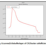 |
Fig. 6:curves ZnSe buffer layer of CIGS solar cell efficiency Click here to View figure |
According to the results of Table(6), the efficiency of laboratory-made CIGS solarcell, based on reference2, is equal to11% which is obtained 19.7% in the simulation by software, due to the lack of restrictions in the laboratory, such as leakage current, environmental pollution.
CONCLUSION
In this paper, at first the CIGS solar cell with a common structure in some papers is stimulated using Silvaco software and yields are shown as well. Then the CdS buffer layer is replaced with three materials with better physical and electrical properties and new efficiencies are obtained. Simulation results show that the Nano crystalline materials MgZnO and ZnMg and ZnSe as buffer layers can be used instead of toxic CdS in CIGS solar cell in order to improve the physical
structure of the solar cell as well as to improve the efficiency by about 0.2%. The solar cell has been designed and simulated in this paper is going to be manufactured and tested in future in the micro electronics laboratory.
REFERENCES
- Saurabh Kumar Pandey, Shaibal Mukherjee. India. “Device modeling and optimization of high-performance thin film CIGS solar cell with MgZnO buffer layer”. IEEE 978-1-4673- 4842-3/13/$31.00©2013.
- Yasuhiro Abe, Takashi Minemoto and Hideyuki Takakura. Japan. “Development of flexible Cu(In,Ga)Se2 Thin film silar cell by Lift-Off Process”. www.intechopen.com (2012).
- N.Shams,A.Afifi,A.Marjani.Iran.”CIGS thin film solar cell simulation”. First National Conference on clen energy (2013).
- F.Troni, F.Dodi, G.Sozzi, R. Menozzi. Italy.” Modeling of Thin-Film CIGS solar cells”.IEEE 978-1-4244-7700-5/10/$26.00©2010.
- Gladyshev, Filin, Puzynin.”Thin film solar cells based on CdTe and Cu(In,Ga)Se2 (CIGS) compounds”. J. Phys.: Conf. Ser. 291 012049 (2011).
- Asghar Haj Seghati.”Principlesand applications ofsolar energy”.page27.
- R.Keshavarz, M.Dehghani. Iran. “ The structuraltypes ofsolar cellsand advantages ofnano-materials withnew technology”.First National Conference onNano materials and Nanotechnology (2012).
- Jesse Huso,1 John L. Morrison,1 Hui Che,1 Jency P. Sundararajan,1 Wei Jiang Yeh,1 David McIlroy,1 Thomas J. Williams,2 and Leah Bergman1. USA. “ ZnO and MgZnONanocrystalline Flexible Films: Optical and Material Properties”. Journal of Nano materials Article ID 691582, 7 pagesdoi:10.1155/2011/691582 (2011).
- Hamdeh, Hussein H.; Ho, J. C.; Oliver, S. A.; Willey, R. J.; OShea, M. J. “ Magnetic properties of ZnMg ferrite fine powders”. URI: http://dx.doi.org/10.1063/1.362330.1996.
- Ashrafi.F, Feiz.S, Fallah.H, Yosefi.S, Shivvaie. M. Iran. “ Production of zinc selenide nano particles and parameters of the structural and optical properties of the reaction”. Letter Paper Physics Conferenceof Iran (2012).

This work is licensed under a Creative Commons Attribution 4.0 International License.
![]()
A New Edition of Web of Science
Journal Impact Factor
2022: 0.5
Five Year: 0.8
Journal is Indexed in

Cabells Whitelist
![]()


